Feedback Feedback
|
Table Of Contents
Line Card Chassis Operations and Troubleshooting
DC Power Up Preparation and Procedures
Power-Related Site Preparation (DC System)
Conductor Characteristics and Low-Voltage Drops
Line Card Chassis Power-Up Procedures
Verifying the Installation of System Cards
Verifying the Installation of a Route Processor and Distributed Route Processor Card
Verifying the Installation of a Modular Services Card
Verifying the Installation of a Physical Layer Interface Module
Verifying the Installation of a Switch Fabric Card
Verifying the Installation of a Fan Controller Card
Troubleshooting the Installation
Troubleshooting Using a Subsystem Approach
Normal Line Card Chassis Startup Sequence
Troubleshooting a Route Processor and Distributed Route Processor
Troubleshooting a Modular Services Card
Troubleshooting a Physical Layer Interface Module
Troubleshooting a Switch Fabric Card
Troubleshooting a Fan Controller Card
Troubleshooting the Power Subsystems
Troubleshooting an AC Rectifier
Troubleshooting a DC Power Entry Module
Troubleshooting the Power Distribution System
Troubleshooting the Cooling Subsystem
Line Card Chassis Fan Controller Card
Isolating Cooling Subsystem Problems
Troubleshooting Using the Alarm Module
Monitoring Critical, Major, and Minor Alarm Status
Alarm Module Alphanumeric Messages
Obtaining Documentation, Obtaining Support, and Security Guidelines
Cisco CRS-1 Carrier Routing System
16-Slot Line Card Chassis Hardware
Operations and Troubleshooting Guide
This guide assists users of the Cisco CRS-1 16-Slot Line Card Chassis with properly operating, maintaining, and troubleshooting their equipment. For documentation on planning for and installing the chassis and its components, see the "Obtaining Documentation, Obtaining Support, and Security Guidelines" section for more information.
Note
Throughout the remainder of this guide, the Cisco CRS-1 16-slot line card chassis is referred to as the line card chassis.
This guide includes the following sections:
•
•
•
Document Conventions
This guide uses the following conventions:
Caution
Note
Warning Definition
See Regulatory Compliance and Safety Information for the Cisco CRS-1 Carrier Routing System for translations of warnings and information about the regulatory, compliance, and safety standards with which the Cisco CRS-1 system conforms.
Changes to This Document
Table 1 lists the technical changes made to this document since it was first released.
Table 1 Changes to This Document
OL-9166-06
April 2012
Corrected Temperature Alarm display in Table 12 to resolve an open caveat.
OL-9166-05
November 2010
Added details about fan speeds and the redundant architecture of the cooling system.
OL-9166-04
May 2010
Added details of a second fan tray with different operating range.
OL-9166-03
September 2007
Corrected values in step 4 of the Line Card Chassis Power-Up Procedures section.
OL-9166-02
October 2006
Corrected PLIM LED status in Verifying the Installation of a Physical Layer Interface Module and Troubleshooting a Physical Layer Interface Module.
Removed reference to alphanumeric LEDs on PLIM.
OL-9166-01
April 2006
Initial release of the document.
Line Card Chassis Operations and Troubleshooting
This section describes various operations and troubleshooting procedures related to the line card chassis. This section includes the following topics:
•
•
•
•
•
•
•
•
•
DC Power Up Preparation and Procedures
This section describes the preparation for and procedures required to properly and successfully power up a DC-powered line card chassis. This section includes excerpts from the line card chassis installation and site planning guides. All applicable power-up preparation information is included in this section.
Note
These procedures provide the following benefits:
•
•
•
•
•
•
•
Power-Related Site Preparation (DC System)
The DC-powered line card chassis requires a total of 12 dedicated 60-A DC input power connections to the power entry modules (PEMs) to provide redundant DC power to all six power zones of the chassis midplane. Six 60-A DC inputs to power shelf 0 (zero) are connected to battery A, and the other six inputs to power shelf 1 are connected to battery B.
The line card chassis DC power system provides 13,200 watts to the chassis. Each DC-powered chassis contains two DC power shelves for 2N redundancy. The shelves contain the input power connectors. Each DC power shelf contains three PEMs. The power shelves and PEMs are field-replaceable units (FRUs). Each shelf has its own disconnect switch and each PEM also has its own disconnect switch.
All DC-equipped line card chassis observe the following guidelines:
•
•
•
•
•
DC power cables must be terminated by cable lugs at the power shelf end. The lugs should be dual hole and able to fit over M6 terminal studs at 0.625-in (15.88-mm) centers.
Conductor Characteristics and Low-Voltage Drops
To avoid signal degradation, a conductor must be large enough to prevent its impedance from creating a voltage drop equal to 2 percent of the reference voltage. In addition, the protective earth conductor must be large enough to carry all the current if the 48-VDC return fails. A large enough protective earth conductor is required for safety reasons. Full fault redundancy is achieved by having conductors of equal size for the protective earth ground and the 48-VDC return of the switch.
For site preparation, proper wire size and insulation must be selected. For planned power distribution, calculations must be done before installation to meet proper voltage drop and temperature rise contingencies.
For wire gauges that prevent unacceptable voltage drops over different lengths of copper wire, see Table 2. For the resistance of 1000 feet of copper wire for each gauge of wire, see Table 3. These references are for planning purposes and might be further subject to local laws and practices.
Table 2 Wire Gauges Preventing Unacceptable Voltage Drops over Different Wire Lengths1
5 A
18 gauge
14 gauge
14 gauge
12 gauge
10 gauge
8 gauge
6 gauge
10 A
14 gauge
12 gauge
10 gauge
8 gauge
8 gauge
6 gauge
2 gauge
15 A
14 gauge
10 gauge
8 gauge
8 gauge
6 gauge
4 gauge
2 gauge
20 A
12 gauge
8 gauge
8 gauge
6 gauge
4 gauge
2 gauge
0 gauge
25 A
12 gauge
8 gauge
6 gauge
4 gauge
4 gauge
2 gauge
0 gauge
30 A
10 gauge
8 gauge
6 gauge
4 gauge
2 gauge
2 gauge
00 gauge
35 A
10 gauge
6 gauge
4 gauge
2 gauge
2 gauge
1 gauge
000 gauge
40 A
8 gauge
6 gauge
2 gauge
2 gauge
2 gauge
0 gauge
000 gauge
45 A
8 gauge
6 gauge
4 gauge
2 gauge
1 gauge
0 gauge
0000 gauge
50 A
8 gauge
4 gauge
4 gauge
2 gauge
1 gauge
00 gauge
—
55 A
8 gauge
4 gauge
2 gauge
2 gauge
0 gauge
00 gauge
—
60 A
8 gauge
4 gauge
2 gauge
2 gauge
0 gauge
00 gauge
—
65 A
6 gauge
4 gauge
2 gauge
1 gauge
0 gauge
000 gauge
—
70 A
6 gauge
4 gauge
2 gauge
1 gauge
00 gauge
000 gauge
—
75 A
6 gauge
4 gauge
2 gauge
1 gauge
00 gauge
000 gauge
—
100 A
4 gauge
2 gauge
1 gauge
00 gauge
000 gauge
—
—
1 Table 1 is for reference only. Industry methods are used to determine the circular mils per gauge.
Example formula is 11.1 x amps x length divided by voltage drop. For example: 11.1 x 60 amps x 100 feet divided by 2 voltage
drop = 33,300 circular mils.
Table 3 Resistance for Each Gauge of Copper Wire
0000
0.0489
10
0.9968
000
0.0617
11
1.2570
00
0.0778
12
1.5849
0
0.0980
13
1.9987
1
0.1237
14
2.5206
2
0.1560
15
3.1778
3
0.1967
16
4.0075
4
0.2480
17
5.0526
5
0.3128
18
6.3728
6
0.3944
19
8.0351
7
0.4971
20
10.1327
8
0.6268
21
12.7782
9
0.7908
22
16.1059
Line Card Chassis Power-Up Procedures
To prevent FRU damage and minimize power line disturbance to other equipment in the facility during line card chassis power up, follow these steps:
Step 1
Step 2
Caution
Step 3
Step 4
a.
b.
c.
Step 5
Step 6
Step 7
Table 4 Voltage at Input Terminal Block (No Board Inserted)
1
2
3
4
5
6
Caution
Step 8
Step 9
Step 10
Table 5 PEM Status Indicators
Power OK
Green
The PEM is operating normally in a powered-up condition.
Fault
Yellow
A fault is detected within the PEM.
DC Input Fail
Yellow
DC input is out of range or is not being provided to the PEM.
OT
Yellow
The PEM is in an over-temperature condition and shutdown has occurred
Breaker Trip
Yellow
The input breaker is in the off position.
Step 11
Step 12
Step 13
Caution
Caution
Cisco CRS-1 Carrier Routing System 16-Slot Line Card Chassis Installation Guide for proper tools and grounding locations.
Step 14
a.
b.
c.
d.
e.
f.
Verifying the Installation of System Cards
This section describes the steps needed to confirm the proper installation of the various system cards. This sections includes:
•
•
•
•
•
Verifying the Installation of a Route Processor and Distributed Route Processor Card
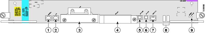
This section describes how to verify the installation of a route processor and distributed route processor (RP and DRP) card in the line card chassis. Figure 1 shows the front panel of the standard RP card.
Figure 1 RP Card Front Panel
Console port
Control Ethernet1 port
AUX port
Management Ethernet port
Hard disk drive slot
Alphanumeric LEDs
PC Card slot
Status LED
Control Ethernet0 port
To verify the installation of an RP and DRP card, follow these steps:
Step 1
Step 2
Step 3
Step 4
a.
b.
c.
d.
e.
f.
Note
Verifying the Installation of a Modular Services Card
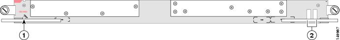
This section describes how to verify the installation of a modular services card (MSC) located in slots 0 through 15 on the rear of the line card chassis. Figure 2 shows the front panel of the MSC.
Figure 2 MSC Front Panel
To verify the installation of an MSC, follow these steps:
Step 1
Step 2
Step 3
Step 4
a.
b.
c.
d.
Verifying the Installation of a Physical Layer Interface Module
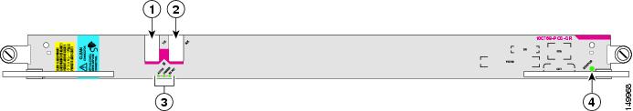
This section describes how to verify the installation of a physical layer interface module (PLIM) located in slots 0 through 15 on the front of the line card chassis. Figure 3 shows a sample PLIM front panel.
Figure 3 PLIM Front Panel (1-Port OC-768 Shown)
To verify the installation of a PLIM, follow these steps:
Step 1
Step 2
Step 3
Step 4
a.
b.
c.
Verifying the Installation of a Switch Fabric Card
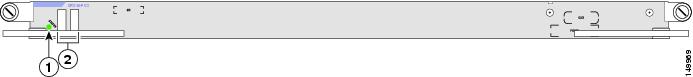
This section describes how to verify the installation of a switch fabric card (SFC). Figure 4 shows the SFC front panel.
Figure 4 SFC Front Panel
To verify the installation of an SFC, follow these steps:
Step 1
Step 2
Step 3
Step 4
a.
b.
c.
d.
Verifying the Installation of a Fan Controller Card
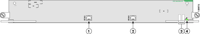
This section describes how to verify the installation of a fan controller (FC) card located in the front of the line card chassis. Figure 5 shows the FC card front panel.
Figure 5 FC Card Front Panel
EXT CLK 1 port (external clock)1
Alphanumeric LEDs
EXT CLK 2 port (external clock)1
Status LED
1 This feature is not currently supported.
To verify the installation of an FC card, follow these steps:
Step 1
Step 2
Step 3
Step 4
a.
b.
c.
d.
Troubleshooting the Installation
This section contains general troubleshooting information to help isolate the cause of difficulties you might encounter during the installation and initial startup of the line card chassis.
It is assumed with the procedures in this section that you are troubleshooting the initial startup of the line card chassis and that the system is running the original configuration. If you altered the original hardware configuration or changed any default configuration settings, the recommendations in this section may not apply.
Troubleshooting procedures are presented in the following sections:
•
•
•
•
Troubleshooting Overview
This section describes the methods used in troubleshooting the line card chassis. The troubleshooting methods are organized according to the major subsystems in the line card chassis.
If you are unable to solve a problem on your own, you can consult a Cisco customer service representative for assistance. When you call, have the following information ready:
•
•
–
•
–
•
•
Troubleshooting Using a Subsystem Approach
To solve a problem, try to isolate the problem to a specific subsystem. Compare current line card chassis behavior with expected line card chassis behavior. Because a startup issue is usually attributable to one component, it is most efficient to examine each subsystem rather than trying to troubleshoot each line card chassis component.
For troubleshooting purposes, the line card chassis consists of the following subsystems:
•
–
–
•
Note
•
Normal Line Card Chassis Startup Sequence
You can generally determine when and where the line card chassis failed during the startup sequence by checking the status and alphanumeric LEDs located on all major components.
In a normal line card chassis startup sequence, the following sequence of events and conditions occurs:
1.
2.
3.
Identifying Startup Issues
Table 6 shows the state of the status and alphanumeric LEDs after a successful system startup.
Table 6 Status and Alphanumeric LEDs at System Startup
RP and DRP
Alphanumeric display
Upper row: ACTV or STBY
Lower row: RPThe active or standby RP and DRP is enabled and recognized by the system. A valid Cisco IOS XR software image is running.
Status LED
Illuminated (Green)
PLIM
Status LED
Illuminated (Green)
MSC
Alphanumeric display
Upper row: IOS-
Lower row: XRThe MSC is enabled and ready for use.
Status LED
Illuminated (Green)
SFC
Alphanumeric display
Upper row: IOS-
Lower row: XRThe SFC is enabled and ready for use.
Status LED
Illuminated (Green)
Alarm module
Alphanumeric display
Upper row: IOS-
Lower row: XRThe alarm module is enabled and ready for use.
LEDs (two arrays)
Critical: Off
Major: Off
Minor: OffNote: The Critical, Major, and Minor LED arrays are redundant. Two sets of LED arrays are present in case any of the LEDs malfunctions.
DC power entry module (PEM)
Power status
PWR OK: On
FAULT: Off
DC INPUT FAIL: Off
OT: Off
BREAKER TRIP: OffThe correct power module voltages are present and no faults are detected.
AC rectifier
Power status
PWR OK: On
FAULT: Off
AC INPUT FAIL: Off
OT: Off
BREAKER TRIP: Off
ILIM: OffThe correct power module voltages are present and no faults are detected.
Fan controller
Alphanumeric display
Upper row: IOS-
Lower row: XRThe fan controller is enabled and ready for use.
Status LED
Illuminated (Green)
Troubleshooting System Cards
If problems occur after verifying the installation of a system card, use this section to determine the cause and fix the problem. The following subsections are included:
•
•
•
•
•
Troubleshooting a Route Processor and Distributed Route Processor
If a RP and DRP fails to operate or power up, review this information:
•
•
•
•
Use the status LED on the RP and DRP faceplate to verify the correct installation of the card:
•
•
•
•
Troubleshooting a Modular Services Card
If a modular services card (MSC) fails to operate or power up, review this information:
•
•
•
•
Use the status LED on the MSC faceplate to verify the correct installation of the MSC:
•
•
•
•
Troubleshooting a Physical Layer Interface Module
If a physical layer interface module (PLIM) fails to operate or power up, review this information:
•
•
•
•
Use the LEDs on the PLIM faceplate to verify the correct installation and operation of the card:
•
•
•
•
•
•
•
•
•
•
•
Troubleshooting a Switch Fabric Card
If a switch fabric card (SFC) fails to operate or power up, review this information:
•
•
•
•
Use the status LED on the SFC faceplate to verify the correct installation of the card:
•
•
•
•
Troubleshooting a Fan Controller Card
If a fan controller (FC) card fails to operate or power up, review this information:
•
•
•
•
Use the status LED on the FC card faceplate to verify the correct installation of the card:
•
•
•
•
Alphanumeric LED Descriptions
Each system card includes an alphanumeric LED display consisting of four characters arranged in two rows (upper and lower). Table 7 lists the alphanumeric LED messages that may appear on any system card.
Table 7 Alphanumeric LED Messages
Upper row: SP
Lower row: RMONIndicates that the SP processor of the CPU is booting up from ROMMON. This is the first step in card bringup.
Upper row: ACTV
Lower row: RPIndicates that this is the active RP.
Note: Only appears on the RP and DRP
Upper row: STBY
Lower row: RPIndicates that this is the standby RP.
Note: Only appears on the RP and DRP
Upper row: IOS-
Lower row: XRIndicates that the node is up and running.
Upper row: PRES
Lower row: ENTIndicates that the card is plugged in but is not booted (probably due to a configuration or some other issue with the card).
Upper row: IN-R
Lower row: ESETIndicates that the card either encountered critical alarms and therefore was shutdown or failed the boot process and hence was shut down. Manual intervention is required to recover the card.
Upper row: ROMM
Lower row: ONIndicates the software state prior to the card booting.
Upper row: MBI-
Lower row: BOOTIndicates that the initial minimum boot image is loading on the card.
Upper row: MBI-
Lower row: RUNIndicates that the minimum boot image (MBI) is running and pulling the appropriate software packages from the active RP to the remote nodes.
Upper row: BRIN
Lower row: GDOWIndicates that the node is down (due to a user configuration or some other error).
Upper row: IOS-
Lower row: XR FIndicates an error that should shut down the card. However, the user has overridden the sequence through a configuration change. Hence, the fail state indicates an error on the card.
Troubleshooting the Power Subsystems
This section contains information to troubleshoot the power subsystems:
•
•
•
Troubleshooting an AC Rectifier
Three AC rectifiers are mounted inside the AC power shelf. Figure 6 shows an AC rectifier.
Figure 6 AC Rectifier
A service processor (SP) module in the power shelf monitors the status of each AC rectifier. The service processor communicates with the system controller on the route processor (RP). The service processor circuitry monitors the following AC rectifier fault and alarm conditions:
•
•
•
•
•
•
Each AC rectifier contains an ID EEPROM that stores information used by control software (for example, part number, serial number, assembly deviation, special configurations, test history, and field traceability data).
AC Rectifier Indicators
Each AC rectifier has power and status indicators. The AC rectifier indicators receive power from both AC power shelves; therefore, the indicators are operational even when the AC rectifier is not powered from its input voltage.
Table 8 lists the AC rectifier status indicators and their functions. Table 9 lists the LED readings during failure conditions.
Table 8 AC Rectifier Status Indicators
PWR OK
Green
The AC rectifier is operating normally with power.
FAULT
Yellow
A fault has been detected in the AC rectifier.
AC INPUT FAIL
Yellow
AC input is out of range or not being provided to the AC rectifier.
OT
Yellow
The AC rectifier is overheated and has been shut down.
BREAKER TRIP
Yellow
The input circuit breaker is off (in the off position).
ILIM
Yellow
The AC rectifier is operating in a current-limiting condition.
Table 9 AC Rectifier LED Failure Conditions
No fault
(power is on)On
Off
Off
Off
Off
Off
Failed AC power
Off
Off
On
Off
Off
Off
Overheated temperature
Off
On
Off
On
Off
Off
Tripped breaker
Off
Off
Off
Off
On
Off
Current limit
Off
Off
Off
Off
Off
On
To troubleshoot an AC rectifier, follow these steps:
Step 1
Step 2
•
•
•
Step 3
–
–
–
•
Note
–
–
–
•
–
–
Because redundant power supplies exist, a problem with the DC output voltage to the backplane from only one AC rectifier should not affect line card chassis operation. Because the line card chassis is equipped with multiple AC rectifiers, it powers on and operates even when one AC rectifier fails.
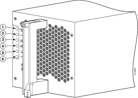
Troubleshooting a DC Power Entry Module
Three DC power entry modules (PEMs) are mounted inside the DC power shelf. Figure 7 shows a DC PEM.
Figure 7 DC PEM
A service processor module (in the power shelf) monitors each PEM and reports the status to the system controller function on the route processor. The service processor detects whether the PEM is present. It also monitors PEM output voltages and current and fault and alarm conditions.
Each PEM contains an ID EEPROM that stores information used by control software (for example, part number, serial number, assembly deviation, special configurations, test history, and field traceability data).
PEM Indicators
Each PEM has power and status indicators. PEM indicators are powered by both DC power shelves; therefore, the indicators are operational even when the PEM is not being powered from its input voltage. Table 10 lists the PEM status indicators and their functions. Table 11 lists the conditions of the LEDs under certain failure conditions.
Table 10 PEM Status Indicators
PWR OK
Green
The PEM is operating normally with power.
FAULT
Yellow
A PEM fault was detected (for example, failed bias supply, over-temperature or over-current, or out-of-range DC output).
DC INPUT FAIL
Yellow
No DC input exists to the PEM, or DC input is out of range.
OT
Yellow
The PEM is overheated and has been shut down.
BREAKER TRIP
Yellow
The circuit breaker has tripped and is in the off position.
Table 11 PEM LED Conditions
No fault
(power is on)On
Off
Off
Off
Off
Failed DC power
Off
Off
On
Off
Off
Overheated temperature
Off
On
Off
On
Off
Tripped breaker
Off
Off
Off
Off
On
To troubleshoot a DC PEM, follow these steps:
Step 1
Step 2
•
•
•
Step 3
–
–
–
•
Note
–
–
–
•
–
–
Because redundant power supplies exist, a problem with the DC output voltage to the backplane from only one PEM should not affect line card chassis operation. Because the line card chassis is equipped with multiple DC PEMs, it powers on and operates even when one PEM fails.
Troubleshooting the Power Distribution System
To troubleshoot the power distribution system, follow these steps.
Step 1
•
•
•
•
•
If the power supplies meet the preceding criteria, then the correct source power is present and within tolerance. The power supplies are functioning properly.
Step 2
•
•
•
Troubleshooting the Cooling Subsystem
The cooling system dissipates the heat generated by the line card chassis and controls the temperature of chassis components. The cooling system has a fully redundant architecture that allows the chassis to continue operating with a single-fault failure (such as a single fan or fan tray failure). See the "Fan Controller Redundancy" section for more information. The architecture also supports a redundant load-sharing design.
The complete chassis cooling system includes:
•
•
•
•
•
The AC rectifiers and DC PEMs in the power shelves also have their own self-contained cooling fans.
All nine fans in a fan tray operate as a group. So, if it is necessary to increase or decrease airflow, all of the fans in the tray increase or decrease their rotation speed together. When two fan trays are operational in a chassis, the speed of the fans in both trays is adjusted together.
Thermal sensors (inlet, exhaust, and hot-spot) located throughout the line card chassis are used to monitor temperature readings and identify when the system is not cooling properly.
Software running on several types of service processor (SP) modules is used to control the operation of the fans. These SP modules are connected by internal Ethernet to the system controller on the route processor (RP).
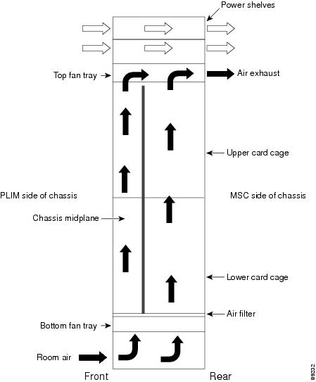
Line Card Chassis Airflow
The airflow through the line card chassis is controlled by a push-pull configuration (see Figure 8). The bottom fan tray pulls in ambient air from the bottom front of the chassis, and the top fan pulls the air up through the card cages and exhausts the warm air from the top rear of the chassis.
Figure 8 Airflow Through Line Card Chassis
Note
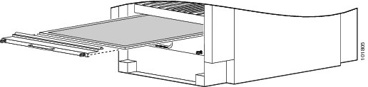
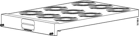
The chassis has a replaceable air filter mounted in a slide-out tray above the lower fan tray. The line card chassis air filter, shown in Figure 9, plugs into the rear (MSC) side of the chassis.
You should change the air filter as often as necessary. In a dirty environment or when you start getting frequent temperature alarms, check the intake grills for debris and check the air filter to see if it needs to be replaced. Before removing the air filter for replacement, you should have a spare filter on hand. Then, when you remove the dirty filter, install the spare filter in the chassis.
Figure 9 Air Filter
Note
Cooling System Operation
The fan control software and related circuitry varies the DC input voltage to individual fans to control their speed. The fan control software and related circuitry increases or decreases the airflow needed to keep the line card chassis operating in a desired temperature range. The chassis cooling system uses multiple fan speeds to optimize cooling, acoustics, and power consumption. Four normal operating fan speeds exist, and one high-speed fan setting is used when a fan tray has failed.
At initial power up, control software powers on the fans to 4300 to 4500 RPM. The fans provide airflow during system initialization and software boot and ensures that there is adequate cooling for the chassis in case the software hangs during boot up. The fan control software is initialized after the routing system software boots up, which can take 3 to 5 minutes. The fan control software then adjusts the fan speeds appropriately.
During normal operation, the chassis averages the temperatures reported by inlet temperature sensors in the lower card cage (or in the upper card cage when the lower cage is empty). To determine the appropriate fan speed for the current temperature, the fan control software compares the average inlet temperature to a lookup table that lists the optimal fan speed for each temperature. The software then sets the fan speed to the appropriate value for the current temperature. The temperature ranges in the lookup table overlap to ensure a proper margin to avoid any type of fan speed oscillation occurring between states.
Note
Thermal Alarms
Local thermal sensors on individual cards monitor temperatures and generate a thermal alarm when the cooling system is not cooling properly. A temperature sensor might be tripped in response to elevated ambient air temperature, a clogged air filter or other airflow blockage, or a combination of these causes. A fan failure causes a fault message, but if no thermal sensors have been tripped, the fan control remains unchanged.
When a thermal sensor reports a thermal alarm, the sensor passes the fault condition to its local service processor (SP), which then notifies the system controller on the route processor (RP). The system controller passes the fault condition to the SP on each fan controller board. The fan control software then takes appropriate action to resolve the fault.
When a thermal sensor is tripped, the fan control software tries to resolve the problem (for example, by increasing fan speed). The software performs a series of steps to prevent chassis components from getting anywhere near reliability-reducing, chip-destroying temperatures. If the fault continues, the software shuts down the card or module to save components.
Quick-Shutdown Mode
The fan controller cards and fan trays have a quick-shutdown mode that kills power when a card or fan tray is disengaged from the chassis midplane. The quick-shutdown mode minimizes inrush current during a hot swap or online insertion and removal (OIR). In normal maintenance conditions, the software gracefully shut downs the power to the failed part, allowing ample time for capacitors to discharge.
Fan Controller Redundancy
This section describes the redundant architecture of the cooling system, which allows the cooling system to continue operating even when certain components have failed.
Both fan controller cards work together to provide fully redundant input power and control logic for fan trays and fans. Each fan controller card receives its input power (-48-VDC) from both the A and B power shelves. The fan controller card then provides one fan tray with input power from the A bus and provides power to the other fan tray from the B bus. This feature ensures that the upper fan tray is powered from the A bus on one fan controller card and from the B bus on the second fan controller card.
In a fully redundant system-one that is equipped with dual power feeds, dual fan controller cards, and dual fan trays-the cooling system can withstand the failure of any one of the following components and still continue to properly cool the chassis:
•
•
•
In the single-failure cases described in this section, the rotational speed of the remaining operational fans changes automatically according to the cooling needs of the chassis.
A double-fault fan failure involves two fan trays, two fan tray boards, two fan controller cards, two power shelves, two power modules (DC PEMs or AC rectifiers), or any combination of two of these components. When a double-fault failure occurs, the system can automatically power down individual cards if the cooling power is insufficient to maintain them. The chassis remains powered on unless both fan trays have failed or thermal alarms indicate a problem serious enough to power down the entire chassis.
Note
For information on the rotational speeds of the fans in revolutions per minute (RPM), see the Line Card Chassis Fan Tray section.
Line Card Chassis Fan Tray
Figure 10 shows a fan tray, which plugs into the rear (MSC) side of the chassis. Each fan tray is hot-swappable and considered a field-replaceable unit. The chassis is designed to run with both fan trays in place.
Figure 10 Fan Tray
Each fan tray contains:
•
•
•
–
–
–
During normal operation, the fans in CRS-16-LCC-FAN-TR= operate in the range of 4000 to 5150 RPM and the fans in CRS-16-LCC-FNTR-B= operate in the range of 3300 to 5150 RPM. The system automatically adjusts the speed of the fans to meet the cooling needs of the entire chassis. If one fan controller card or one power feed fails, the fans continue to operate within the ranges specified above (up to 5150 RPM). If one fan tray fails completely, or is removed, the fans in the remaining fan tray automatically speed up to the maximum rotational limit, which is 6700 RPM for CRS-16-LCC-FAN-TR= and 6600 RPM for CRS-16-LCC-FNTR-B=.
Note
Line Card Chassis Fan Controller Card
A line card chassis contains two fan controller (FC) cards, shown in Figure 11.
Figure 11 FC Card Front Panel
EXT CLK 1 port (external clock)1
Alphanumeric LEDs
EXT CLK 2 port (external clock)1
Status LED
1 This feature is not currently supported.
The FC cards provide the following functions:
•
•
•
•
•
•
Isolating Cooling Subsystem Problems
The chassis cooling system dissipates heat generated by the routing system and controls the temperature of components in the fabric card chassis and line card chassis. The cooling system has a fully redundant architecture that allows the routing system to continue operating with a single-fault failure (such as a single fan or fan tray failure). Thermal sensors (on cards and modules, and inlet, exhaust, and hot-spot) are located throughout the chassis to monitor temperature readings.
A thermal alarm is generated when the system is not cooling properly. A temperature sensor might trip in response to any of the following causes:
•
•
•
The fan controller attempts to maintain the temperature within the chassis by varying the speed of the fans. When the chassis temperature threshold is exceeded, a thermal alarm is generated. If the fault continues, the software shuts down the card or module to save components.
To isolate a problem with the chassis cooling system if you have an over-temperature condition, follow these steps.
Step 1
•
–
–
–
Step 2
If the blower module still does not function, go to Step 3.
Step 3
•
–
–
•
•
–
–
Consult your Cisco representative if replacing the power module does not fix the problem.
Troubleshooting Using the Alarm Module
The line card chassis processor subsystem consists of the RPs, PLIMs with MSCs, and alarm module. A minimally configured line card chassis must have an RP installed in slot 7 of the upper card cage. If the router is equipped with an optional, redundant RP, that RP must be installed in the far left slot in the lower card cage (slot 8).
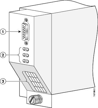
Each AC or DC power shelf contains an alarm module that monitors the status of the power shelf and provides an external interface for system alarms. The same alarm module (see Figure 12) is used in all power shelves.
Note
Figure 12 Alarm Module
The alarm module performs the following functions:
•
–
–
•
•
–
–
Monitoring Critical, Major, and Minor Alarm Status
The alarms can warn of an over-temperature condition:
•
•
•
•
The RP continuously polls the system for the values of the temperature, voltage, current, and fan speed. If a threshold value is exceeded, the RP sets the appropriate alarm severity level on the alarm card, which lights the corresponding LED, and energizes the appropriate alarm display relays to activate any external audible or visual alarms wired to the alarm display. The RP also logs a message about the threshold violation on the system console. The status LEDs indicate the following:
•
•
•
Note
Alarm Module Alphanumeric Messages
If an alarm occurs, the display indicates the card or component that is having a problem.
The Critical, Major, and Minor alarm LEDs are interpreted with the message displayed on the alphanumeric display. For example, if the Minor LED is lit and the alphanumeric display shows 0 SM0 SP, then a minor alarm exists on 0/SM0/SP. If the Major LED is lit and the alphanumeric display shows UPPR FAN-TRAY ALRM, then a major alarm is generated by the upper fan tray.
The status of the fans should be verified using the show environment fans command to check for failed fans. In both examples, checking the output of the show logging command provides details of the alarm (a message in the form of "MINOR alarm generated by <component_name>" or "MAJOR alarm generated by <component_name>." Table 12 lists the various states of the alarm module LEDs.
Table 12 Alarm Module LED Descriptions
IOS XR
System is operating properly
—
UPPR SNGL FANx ALRM or
LWR SNGL FANx ALRM
(x = 1-9)Single fan failure
Minor
MULT FAN FAIL ALRM
Multiple fan failure in one or more trays
Minor—fewer than 6 fans
Major—6 to 11 fans
Critical—12 or more fansUPPR FAN- TRAY ALRM or
LWR FAN- TRAY ALRMFan tray removal or failure1
Major
FAN CTRL FAIL ALRM
Fan controller removal or failure
Major
SNGL PEM xx ALRM
(xx could be A0, A1, A2, B0, B1, or B2)Single PEM failure or inserted PEM that is powered off
(power shelf is still on)Minor
MULT PEM FAIL ALRM
Multiple PEM failure or inserted PEM that is powered off
(power shelf is still on)Major
ZONE x FAIL ALRM2
(x = Zone number of failure)Single zone failure due to multiple PEM failure or removal
Critical
MULT ZONE FAIL ALRM
Multiple zone failure due to multiple PEM failure or removal
Critical
PEM SHLF x ALRM (x = A or B)
PEM shelf failure or inserted power shelf that is powered off
Major
R/S/M
Single-node temperature alarm
Varies based on temperature level
MULT NODE TEMP ALRM
Multi-node temperature alarm
Varies based on temperature level
NODE R/S/M VLTG ALRM
Single-node voltage alarm
Varies based on how far the voltage is out of range
MULT NODE VLTG ALRM
Multi-node voltage alarm
Varies based on how far the voltage is out of range
1 If both fan trays are removed, the entire system shuts down immediately. This occurs as soon as the software detects that both fan trays are out of the chassis, irrespective of any other conditions. In other temperature-based cases, nodes are shut down one by one. Fan fray shutdown would also cause the fan trays to stop and cause a complete system shutdown over time.
2 This may be a rare condition because most PEMs have more than one zone attached to it.
Obtaining Documentation, Obtaining Support, and Security Guidelines
For information on obtaining documentation, obtaining support, providing documentation feedback, security guidelines, and also recommended aliases and general Cisco documents, see the monthly What's New in Cisco Product Documentation, which also lists all new and revised Cisco technical documentation, at:
http://www.cisco.com/en/US/docs/general/whatsnew/whatsnew.html