Feedback Feedback
|
Table Of Contents
Cisco Connected Grid 2G/3G/4G Multimode LTE GRWIC Installation and Configuration Guide
Supported Cisco Antennas and Cables by Case
Preventing Electrostatic Discharge Damage
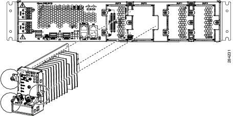
Installing and Removing the Module
Installation Warning Statements
Regulatory and Compliance Information
Verifying Signal Strength and Service Availability
Configuring a Modem Data Profile
Configuring the Cellular Interface
Configuring DDR (Dial-on Demand Routing)
Basic Cellular Interface Configuration
Tunnel over Cellular Interface Configuration
4G-LTE Wireless Modem as Backup with NAT and IPSec
Troubleshooting and Diagnostics
Verifying Service Availability
Changing the PRL Region on the Modem
Retrieving the Electronic Serial Number (ESN)
Converting Hexadecimal ESN to Decimal Notation
Hardware Overview and Installation
Supported Cisco Antennas and Accessories
Regulatory, Compliance, and Safety Information
Cisco Connected Grid 2G/3G/4G Multimode LTE GRWIC Installation and Configuration Guide
First Published: November, 2011OL-25668-01
This document provides an overview of hardware and configuration information for Cisco Connected Grid 2G/3G/4G Multimode LTE (Long-Term Evolution) GRWIC, a single-wide grid router WAN interface card supported on Cisco 2010 Connected Grid Router (CGR).
This document covers the following topics:
•
Installing and Removing the Module
•
•
Feature History
Cisco Feature Navigator provides information about platform support, software image support, including software image and their supported software release, feature set, or platform.
You can access Cisco Feature Navigator, by going to http://www.cisco.com/go/cfn. An account on Cisco.com is not required.
Table 1 lists the release history for this feature.
Note
Features
The 4G GRWIC offers the following key features:
•
•
•
•
The 4G GRWIC supports the following:
•
•
•
•
•
•
•
•
Hardware Overview
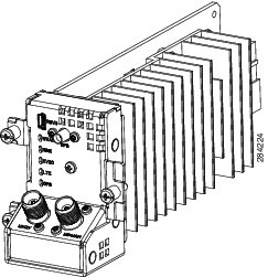
The 4G GRWIC is a cellular modem interface card for the Cisco 2010 Connected Grid Router that provides a primary wireless WAN data link interface over a cellular network. It is a High-Speed Packet Access (HSPA) multiband, multiservice, single-wide GRWIC allowing transmission and distribution communication between utilities and substations through 4G technologies. The module is backward-compatible with previous generation technologies and frequency bands.
This section cover the following topics:
•
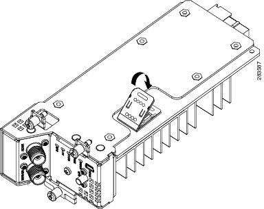
Figure 1 The Cisco Connected Grid 2G/3G/4G Multimode LTE GRWIC
For instruction on how to install a single-wide interface card in Cisco access routers, see Connecting Cisco Grid Router WAN Interface Cards:
http://www.cisco.com/en/US/docs/routers/access/2000/CGR2010/hardware/GRWIC/CGR2010_GRWIC.html
The module is compatible with the following frequency bands:
•
–
–
•
–
–
•
–
–
RF Specifications
The following are additional 4G specifications of the card:
•
•
Multimode Modem
The 4G GRWIC comes with a Sierra Wireless multi-mode modem that provides the RF interface for the modem. The modem complies with PCI Express Mini Card Electromechanical Specification, revision 1.2. The hardware includes the following:
•
•
The modem supports one of the following standards:
•
Note
Note
•
Sierra Wireless AirPrime MC7700, MC7750, and MC7710 modules each deliver up to 100 Mbps download speeds and 50 Mbps upload speeds (within 20 MHz bandwidth), integrated GPS capabilities, and support for both Linux and Windows.
Envrionmental Specifications
Table 2 lists the environmental specifics of the 4G GRWIC.
Power Specifications
4G GRWIC draws +10.8V, +5V and +3.3V from the host platform. The +10.8 V is used exclusively for the modem +3.3 V power requirement. The +3.3V is for the board I/O. The power sourcing of +10.8 V rail (5000 mW) from the host precludes the need for any onboard modem power storage. The +5 V from the host is used to create a +3.3 V I/O voltage for the CPU, FPGA, FLASH, analog Muxes and LEDs, as well as the +1.0 V CPU Core voltage.
Note
Table 3 and Table 4 list the power specification of the 4G GRWIC.
Memory Specifications
Table 5 lists the memory specifications of the 4G GRWIC.
Kit Contents
Cisco Connected Grid 2G/3G/4G Multimode LTE GRWIC is a customer-replaceable unit and can be ordered by referencing the following information.
Table 6 describes the Cisco 4G WWAN GRWIC product SKUs.
Ports and LEDs
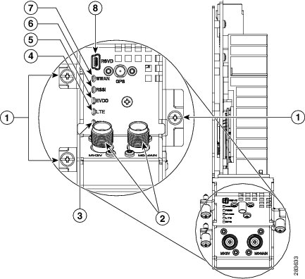
Figure 2 shows the GRWIC-4G-LTE front panel.
Figure 2 Front Panel of the Cisco GRWIC-4G-LTE
1
Mounting Screws
2
Antenna Connectors—M1/DIV, M0/MAIN
3
LED—GPS
4
LED—LTE
5
LED—EVDO
6
LED—RSSI
7
LED—WWAN
8
RSVD Port
9
Antenna Connector—GPS
Table 7 lists the ports and the LED indicators and describes their behavior. The LEDs provide a visual indication of the available services.
Table 7 Cisco 4G GRWIC by Mode, Operating Region, and Frequencies
Description
RSVD
The RSVD (Reserved) port. Used as a diagnostic port not required for normal activation or operation. This port supports modem debug or provisioning. See Modem Troubleshooting.
Antenna Connectors
•
•
•
For details, see Supported Cisco Antennas and Cables by Case.
WWAN
Indicates the GRWIC modem status.
•
•
•
•
For information on modem settings, see Modem Settings.
RSSI
Indicates the level of signal strength received by the GRWIC software.
•
•
•
•
•
EVDO
Indicates whether HSDPA (High-Speed Downlink Packet Access) or EVDO (Evolution, Data Only) is in service.
•
•
•
LTE
Indicates whether LTE (Long-Term Evolution) is in service.
GPS
Indicates whether GPS (Global Positioning System) is in service.
•
•
Supported Cisco Antennas and Cables by Case
Table 8 lists the Cisco antennas that are supported for use on the 4G GRWIC.
Note
Or the Cisco CGR 1000 and 2000 Series Connected Grid Antennas Guide at:
http://www.cisco.com/en/US/docs/routers/connectedgrid/antennas/installing/cg_antenna_install_guide.html
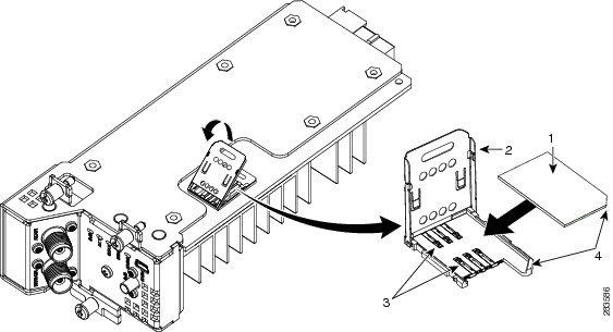
Installing the SIM Card
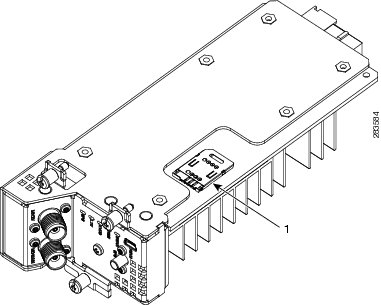
The SIM card socket is located on the bottom side of the GRWIC as shown in Figure 3.
Figure 3 Location of the SIM Socket
Preventing Electrostatic Discharge Damage
Electrostatic Discharge (ESD) damage can occur when electronic cards or components are handled improperly, and can result in complete or intermittent failures.
To prevent ESD damage, follow these guidelines:
•
•
•
•
•
Warning
Caution
DETAILED STEPS
To install the SIM card:
Step 1
Step 2
Step 3
Step 4
Installing and Removing the Module
Note
Before You Begin Installation
Before installing the module, verify that the following guidelines have been met:
•
•
•
•
•
•
•
Installation Warning Statements
This section includes the basic installation warning statements. Translations of these warning statements appear in the Regulatory Compliance and Safety Information for Cisco Connected Grid Router 1000 Series Routers documents.
Warning
Warning
140°F (60°C) Statement 1047
WarningInstalling the Module
To install the module into an available slot in the router:
Caution
Step 1
Step 2
Step 3
Removing the Module
To remove the module from the router:
Caution
Step 1
Step 2
Installing the Antenna Cable
The swivel dipole antenna requires two LMR-400-DB TNC(m) to N(m) coaxial cables to connect to the female TNC connectors on the faceplate of the 4G GRWIC.
To install the cables, you will need a pair of needle-nose pliers.
Step 1
Step 2
Note
Step 3
Step 4
Note
Regulatory and Compliance Information
For regulatory compliance and safety information for the module, refer to the Connected Grid Router 2000 Series Regulatory Compliance and Safety Information document.
http://www.cisco.com/en/US/docs/routers/access/2000/CGR2010/hardware/rcsi/rcsiCGR2000series.html
Software Overview
Cisco 4G Wireless WAN GRWICs operate over Fourth Generation (4G) Long-Term Evolution (LTE) cellular networks and Third Generation (3G) cellular networks.
Overview of 4G-LTE Networks
4G-LTE mobile specification provides multi-megabit bandwidth, more efficient use of the radio network, latency reduction, and improved mobility. LTE solutions target new cellular networks. These networks are designed to support up to 300 Mbps peak rates in the downlink and up to 75 Mbps peak rates in the uplink. The throughput of these networks is higher than the existing 3G networks.
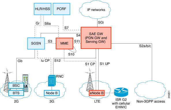
Figure 4 shows a 4G-LTE packet core network and the network elements it contains.
Figure 4 4G-LTE Packet Core Network Architecture
Configuring the Module
This section covers the following topics:
•
Prerequisites
To configure the 4G GRWIC, you must meet the following requirements:
•
•
•
Configuration Restrictions
Be aware of the following restrictions that exist with a cellular network:
•
•
•
•
Data Account Provisioning
Note
Note
To provision your data account, see the following topics:
•
•
Verifying Signal Strength and Service Availability
To verify the signal strength and service availability on your modem, use the following commands in privileged EXEC mode.
•
•
•
•
•
DETAILED STEPS
Configuring a Modem Data Profile
To configure or create a new modem data profile, issue the command, cellular slot/wic/port lte profile create profile-number apn authentication username password ipv4 in privileged EXEC mode. Table 9 describes the command parameters.
Example:router#cellular 0/0/0 profile create 2 apn.com chap username1 password1 ipv4
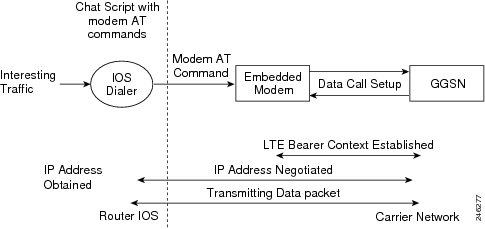
Data Call Setup
A data call is a call setup through a signaling protocol (for example, ISDN D Channel signaling) on the Public Switching Telephony Network (PSTN) to a Network Access Server (NAS) to transfer data, either as a byte stream (for example, terminal emulation) or in a packet format (for example, PPP packets) from a data terminal (such as a PC) to a data network (such as the Internet).
To verify data call setup, see, Verifying Data Call Setup.
To set up a data call, use the following topics:
•
•
Figure 5 shows a typical data call setup.
Figure 5 Data Call Setup with the 4G GRWIC
Configuring the Cellular Interface
To configure the cellular interface, enter the following commands starting in EXEC mode.
•
•
•
•
•
DETAILED STEPS
Note
Configuring DDR (Dial-on Demand Routing)
This section contains the commands to configure Dial-On-Demand Routing (DDR) for the cellular interface:
•
•
•
•
•
•
•
•
•
•
•
•
•
•
•
Note
DETAILED STEPS
Configuring DDR Backup
To monitor the primary connection and initiate the backup connection when needed, the router can use one of the following methods:
•
•
•
Configuring Interfaces to Use a Backup Interface
Note
To configure one or more interfaces to use a backup interface, use the following commands, beginning in global configuration mode.
SUMMARY STEPS
1.
2.
3.
DETAILED STEPS
Configuring DDR Backup Using Dialer Watch
To initiate dialer watch, you must configure the interface to perform DDR and backup. Use traditional DDR configuration commands, such as dialer maps, for DDR capabilities. To enable dialer watch on the backup interface and create a dialer list, use the following commands in interface configuration mode.
SUMMARY STEPS
1.
2.
3.
4.
5.
6.
7.
8.
9.
DETAILED STEPS
Configuring DDR Backup Using Floating Static Route
To configure a floating static default route on the secondary interface beginning in the global configuration mode, perform the following tasks.
Note
SUMMARY STEPS
1.
2.
DETAILED STEPS
Configuration Examples
This section provides the following configuration examples:
•
•
•
Basic Cellular Interface Configuration
The following example shows how to configure the cellular interface to be used as a primary and is configured as the default route:
router# show running-configurationchat-script lte "" "AT!CALL1" TIMEOUT 20 "OK"interface Cellular0/0/0ip address negotiatedencapsulation slipload-interval 30dialer in-banddialer idle-timeout 0dialer string ltedialer-group 1no peer default ip addressasync mode interactiverouting dynamicip route 172.22.1.10 255.255.255.255 Cellular0/0/0dialer-list 1 protocol ip permitline 0/0/0script dialer ltemodem InOutno exectransport input alltransport output allTunnel over Cellular Interface Configuration
The following example shows how to configure the static IP address when a tunnel interface is configured with ip address unnumbered cellular interface:
interface Tunnel2ip unnumbered Cellular0/3/0tunnel source Cellular0/3/0tunnel destination 128.107.x.yinterface Cellular0/3/0ip address negotiatedip virtual-reassemblyencapsulation slipno ip mroute-cachedialer in-banddialer idle-timeout 0dialer string dial<carrier>dialer-group 1async mode interactive! traffic of interest through the tunnel/cellular interfaceip route 10.10.0.0 255.255.0.0 Tunnel24G-LTE Wireless Modem as Backup with NAT and IPSec
The following example shows how to configure the 4G-LTE wireless modem on the router as backup with NAT and IPSec:
Note
ip dhcp excluded-address 10.4.0.254!ip dhcp pool gsmpoolnetwork 10.4.0.0 255.255.0.0dns-server 209.165.201.1 203.0.113.0default-router 10.4.0.254!!chat-script lte "" "AT!CALL1" TIMEOUT 20 "OK"crypto isakmp policy 1encr 3desauthentication pre-sharecrypto isakmp key address 192.0.2.0!!crypto ipsec transform-set ah-sha-hmac esp-3des!crypto map gsm1 10 ipsec-isakmpset peer 192.0.2.0set transform-setmatch address 103!!interface ATM0/0/0no ip addressip virtual-reassemblyload-interval 30no atm ilmi-keepalivedsl operating-mode auto!interface ATM0/0/0.1 point-to-pointbackup interface Cellular0/3/0ip nat outsideip virtual-reassemblyno snmp trap link-statuspvc 0/35pppoe-client dial-pool-number 2!!interface Cellular0/3/0ip address negotiatedip nat outsideip virtual-reassemblyencapsulation slipno ip mroute-cachedialer in-banddialer idle-timeout 0dialer stringdialer-group 1async mode interactivecrypto map gsm1!interface Vlan104description used as default gateway address for DHCP clientsip address 10.4.0.254 255.255.0.0ip nat insideip virtual-reassembly!interface Dialer2ip address negotiatedip mtu 1492ip nat outsideip virtual-reassemblyencapsulation pppload-interval 30dialer pool 2dialer-group 2ppp authentication chap callinppp chap hostname cisco@dsl.comppp chap password 0 ciscoppp ipcp dns requestcrypto map gsm1!ip local policy route-map track-primary-ifip route 209.165.200.225 255.255.255.224 Dialer2 track 234ip route 209.165.200.225 255.255.255.224 Cellular0/3/0 254!!ip nat inside source route-map nat2cell interface Cellular0/3/0 overloadip nat inside source route-map nat2dsl interface Dialer2 overload!ip sla 1icmp-echo 209.131.36.158 source-interface Dialer2timeout 1000frequency 2ip sla schedule 1 life forever start-time nowaccess-list 1 permit anyaccess-list 2 permit 10.4.0.0 0.0.255.255access-list 3 permit anyaccess-list 101 permit ip 10.4.0.0 0.0.255.255 anyaccess-list 102 permit icmp any host 209.131.36.158access-list 103 permit ip host 198.51.100 209.165.200.224 0.0.255.255access-list 103 permit ip host 203.0.113.254 209.165.200.124 0.0.255.255dialer-list 1 protocol ip list 1dialer-list 2 protocol ip permit!!route-map track-primary-if permit 10match ip address 102set interface Dialer2!route-map nat2dsl permit 10match ip address 101match interface Dialer2!route-map nat2cell permit 10match ip address 101match interface Cellular0/3/0!line 0/3/0exec-timeout 0 0script dialer dialloginmodem InOutSNMP MIBs
The following MIBs are supported on the Cisco Connected Grid 2G/3G/4G Multimode LTE GRWIC:
•
•
•
You can download the MIBs from the Cisco MIB Locator at http://www.cisco.com/go/mibs.
This section provides a brief description of SNMP MIBs and contains the following topics:
SNMP Requirements
The following are SNMP-related requirements for the 4G GRWIC:
•
•
SNMP MIB Overview
Simple Management Network Protocol (SNMP) development and its use is centered around the Management Information Base (MIB). An SNMP MIB is an abstract database, a conceptual specification for information that a management application may read and modify in a certain form. This does not imply that the information is kept in the managed system in that same form. The SNMP agent translates between the internal data structures and formats of the managed system and the external data structures and formats defined for the MIB.
The SNMP MIB is a tree structure with conceptual tables. (Cisco 4G MIB is discussed in detail in the next section.) Relative to this tree structure, the term MIB is used in two senses. In one sense, it is actually a MIB branch, usually containing information for a single aspect of technology, such as a transmission medium or a routing protocol. A MIB used in this sense is more accurately called a MIB module, and is usually defined in a single document. In the other sense, a MIB is a collection of such branches. Such a collection might comprise, for example, all the MIB modules implemented by a given agent, or the entire collection of MIB modules defined for SNMP.
A MIB is a tree where the leaves are individual items of data called objects. An object may be, for example, a counter or a protocol status. MIB objects are also sometimes called variables.
MIBs can be classified into three categories:
•
•
•
MIB Links
To locate and download the following MIBs for selected platforms, Cisco software releases, and feature sets, search the MIB name in Cisco MIB Locator found at: http://www.cisco.com/go/mibs
•
•
•
Troubleshooting and Diagnostics
This section provides the necessary background information and resources available for troubleshooting the Cisco Cisco Connected Grid 2G/3G/4G Multimode LTE GRWIC.
For LED descriptions, see Ports and LEDs.
•
•
•
Verifying Data Call Setup
To verify the data call setup, follow these steps:
Step 1
Step 2
•
•
•
•
•
•
•
Step 3
Checking Signal Strength
If the Received Signal Strength Indication (RSSI) level is very low (for example, if it is less than -110 dBm) follow these steps:
Step 1
Step 2
Step 3
Verifying Service Availability
The following is sample show cellular all command output for a scenario where the antenna is disconnected and a modem data profile has not been created. The errors in this case have been indicated with the symbols "<--":
router# show cellular 0/0/0 allLoad for five secs: 0%/0%; one minute: 0%; five minutes: 1%Time source is hardware calendar, 19:40:43.239 UTC Wed Nov 8 2006Hardware Information====================Modem Firmware Version = H1_0_0_7MCAP G:/WS/Modem Firmware built = 10/26/06Hardware Version = 1.0International Mobile Subscriber Identity (IMSI) = <specific sim number>International Mobile Equipment Identity (IMEI) = <specific modem number>Factory Serial Number (FSN) = X2819460388100DModem Status = OnlineCurrent Modem Temperature = 38 deg C, State = NormalProfile Information====================* - Default profile <-- No profile here.Data Connection Information===========================Profile 1, Packet Session Status = INACTIVEInactivity Reason = Normal inactivate stateProfile 2, Packet Session Status = INACTIVEInactivity Reason = Normal inactivate stateProfile 3, Packet Session Status = INACTIVEInactivity Reason = Normal inactivate stateProfile 4, Packet Session Status = INACTIVEInactivity Reason = Normal inactivate stateProfile 5, Packet Session Status = INACTIVEInactivity Reason = Normal inactivate stateProfile 6, Packet Session Status = INACTIVEInactivity Reason = Normal inactivate stateProfile 7, Packet Session Status = INACTIVEInactivity Reason = Normal inactivate stateProfile 8, Packet Session Status = INACTIVEInactivity Reason = Normal inactivate stateProfile 9, Packet Session Status = INACTIVEInactivity Reason = Normal inactivate stateProfile 10, Packet Session Status = INACTIVEInactivity Reason = Normal inactivate stateProfile 11, Packet Session Status = INACTIVEInactivity Reason = Normal inactivate stateProfile 12, Packet Session Status = INACTIVEInactivity Reason = Normal inactivate stateProfile 13, Packet Session Status = INACTIVEInactivity Reason = Normal inactivate stateProfile 14, Packet Session Status = INACTIVEInactivity Reason = Normal inactivate stateProfile 15, Packet Session Status = INACTIVEInactivity Reason = Normal inactivate stateProfile 16, Packet Session Status = INACTIVEInactivity Reason = Normal inactivate stateNetwork Information===================Current Service Status = No service, Service Error = None <-- No service means there is no connection to the network.Current Service = CombinedPacket Service = NonePacket Session Status = InactiveCurrent Roaming Status = HomeNetwork Selection Mode = AutomaticCountry = USA, Network = CinglrMobile Country Code (MCC) = 310Mobile Network Code (MNC) = 380Location Area Code (LAC) = 6042Routing Area Code (RAC) = 255Cell ID = 0Primary Scrambling Code = 0PLMN Selection = AutomaticRadio Information=================Current Band = None, Channel Number = 0Current RSSI = -110 dBm <-- Either no antenna is present, non-functional, or out of network.Modem Security Information==========================Card Holder Verification (CHV1) = DisabledSIM Status = OKSIM User Operation Required = NoneNumber of Retries remaining = 3Successful Call Setup
The following sample output was taken when a call was set up using a chat script. It shows a received IP address from the network. Call setup is successful, and data path is open.
debug modemdebup chatdebug ppp negotiationdebug ppp eventdebup ppp errorrouter#Nov 8 20:04:42.295: CHAT0/3/0: Attempting async line dialer scriptNov 8 20:04:42.295: CHAT0/3/0: Dialing using Modem script: <carrier> & System script: noneNov 8 20:04:42.299: CHAT0/3/0: process startedNov 8 20:04:42.299: CHAT0/3/0: Asserting DTRNov 8 20:04:42.299: CHAT0/3/0: Chat script <carrier> started <--- chat script invokedNov 8 20:04:42.299: CHAT0/3/0: Sending string: atdt*98*1#Nov 8 20:04:42.299: CHAT0/3/0: Expecting string: CONNECTNov 8 20:04:42.343: CHAT0/3/0: Completed match for expect: CONNECTNov 8 20:04:42.343: CHAT0/3/0: Chat script <carrier> finished, status = Success <--- successful communication with modemNov 8 20:04:42.395: TTY0/3/0: no timer type 1 to destroyNov 8 20:04:42.395: TTY0/3/0: no timer type 0 to destroyNov 8 20:04:42.395: TTY0/3/0: no timer type 2 to destroyNov 8 20:04:44.395: %LINK-3-UPDOWN: Interface Cellular0/3/0, changed state to upNov 8 20:04:44.395: Ce0/3/0 PPP: Using dialer call directionNov 8 20:04:44.395: Ce0/3/0 PPP: Treating connection as a calloutNov 8 20:04:44.395: Ce0/3/0 PPP: Session handle[7E000089] Session id[46]Nov 8 20:04:44.395: Ce0/3/0 PPP: Phase is ESTABLISHING, Active OpenNov 8 20:04:44.395: Ce0/3/0 PPP: No remote authentication for call-outNov 8 20:04:44.395: Ce0/3/0 LCP: O CONFREQ [Closed] id 75 len 16Nov 8 20:04:44.395: Ce0/3/0 LCP: ACCM 0x000A0000 (0x0206000A0000)Nov 8 20:04:44.395: Ce0/3/0 LCP: MagicNumber 0x179E8E46 (0x0506179E8E46)Nov 8 20:04:44.395: Ce0/3/0 LCP: I CONFREQ [REQsent] id 83 len 25Nov 8 20:04:44.395: Ce0/3/0 LCP: ACCM 0x00000000 (0x020600000000)Nov 8 20:04:44.395: Ce0/3/0 LCP: AuthProto CHAP (0x0305C22305)Nov 8 20:04:44.395: Ce0/3/0 LCP: MagicNumber 0x374C7C61 (0x0506374C7C61)Nov 8 20:04:44.395: Ce0/3/0 LCP: PFC (0x0702)Nov 8 20:04:44.395: Ce0/3/0 LCP: ACFC (0x0802)Nov 8 20:04:44.395: Ce0/3/0 LCP: O CONFREJ [REQsent] id 83 len 8Nov 8 20:04:44.395: Ce0/3/0 LCP: PFC (0x0702)Nov 8 20:04:44.395: Ce0/3/0 LCP: ACFC (0x0802)Nov 8 20:04:44.399: Ce0/3/0 LCP: I CONFACK [REQsent] id 75 len 16Nov 8 20:04:44.399: Ce0/3/0 LCP: ACCM 0x000A0000 (0x0206000A0000)Nov 8 20:04:44.399: Ce0/3/0 LCP: MagicNumber 0x179E8E46 (0x0506179E8E46)Nov 8 20:04:44.399: Ce0/3/0 LCP: I CONFREQ [ACKrcvd] id 84 len 21Nov 8 20:04:44.399: Ce0/3/0 LCP: ACCM 0x00000000 (0x020600000000)Nov 8 20:04:44.399: Ce0/3/0 LCP: AuthProto CHAP (0x0305C22305)Nov 8 20:04:44.399: Ce0/3/0 LCP: MagicNumber 0x374C7C61 (0x0506374C7C61)Nov 8 20:04:44.399: Ce0/3/0 LCP: O CONFACK [ACKrcvd] id 84 len 21Nov 8 20:04:44.399: Ce0/3/0 LCP: ACCM 0x00000000 (0x020600000000)Nov 8 20:04:44.399: Ce0/3/0 LCP: AuthProto CHAP (0x0305C22305)Nov 8 20:04:44.399: Ce0/3/0 LCP: MagicNumber 0x374C7C61 (0x0506374C7C61)Nov 8 20:04:44.399: Ce0/3/0 LCP: State is OpenNov 8 20:04:44.399: Ce0/3/0 PPP: Phase is AUTHENTICATING, by the peerNov 8 20:04:44.403: Ce0/3/0 CHAP: I CHALLENGE id 1 len 35 from "UMTS_CHAP_SRVR"Nov 8 20:04:44.403: Ce0/3/0 CHAP: Using hostname from interface CHAPNov 8 20:04:44.403: Ce0/3/0 CHAP: Using password from interface CHAPNov 8 20:04:44.403: Ce0/3/0 CHAP: O RESPONSE id 1 len 40 from "<username configured on the cellular interface>"Nov 8 20:04:44.407: Ce0/3/0 CHAP: I SUCCESS id 1 len 4Nov 8 20:04:44.407: Ce0/3/0 PPP: Phase is FORWARDING, Attempting ForwardNov 8 20:04:44.407: Ce0/3/0 PPP: Phase is ESTABLISHING, Finish LCPNov 8 20:04:44.407: Ce0/3/0 PPP: Phase is UP<-- Password Authentication Protocol (PAP), and the Challenge Handshake Authentication Protocol (CHAP) succeeded.Nov 8 20:04:44.407: Ce0/3/0 IPCP: O CONFREQ [Closed] id 1 len 22Nov 8 20:04:44.407: Ce0/3/0 IPCP: Address 0.0.0.0 (0x030600000000)Nov 8 20:04:4.407: Ce0/3/0 IPCP: PrimaryDNS 0.0.0.0 (0x810600000000)Nov 8 20:04:44.407: Ce0/3/0 IPCP: SecondaryDNS 0.0.0.0 (0x830600000000)Nov 8 20:04:44.407: Ce0/3/0 PPP: Process pending ncp packetsNov 8 20:04:45.411: Ce0/3/0 IPCP: I CONFNAK [REQsent] id 1 len 16Nov 8 20:04:45.411: Ce0/3/0 IPCP: PrimaryDNS 10.11.12.13 (0x81060A0B0C0D)Nov 8 20:04:45.411: Ce0/3/0 IPCP: SecondaryDNS 10.11.12.14 (0x83060A0B0C0E)Nov 8 20:04:45.411: Ce0/3/0 IPCP: O CONFREQ [REQsent] id 2 len 22Nov 8 20:04:45.411: Ce0/3/0 IPCP: Address 0.0.0.0 (0x030600000000)Nov 8 20:04:45.411: Ce0/3/0 IPCP: PrimaryDNS 10.11.12.13 (0x81060A0B0C0D)Nov 8 20:04:45.411: Ce0/3/0 IPCP: SecondaryDNS 10.11.12.14 (0x83060A0B0C0E)Nov 8 20:04:45.459: Ce0/3/0 IPCP: I CONFREQ [REQsent] id 25 len 4Nov 8 20:04:45.459: Ce0/3/0 IPCP: O CONFACK [REQsent] id 25 len 4Nov 8 20:04:45.459: Ce0/3/0 IPCP: I CONFNAK [ACKsent] id 2 len 22Nov 8 20:04:45.459: Ce0/3/0 IPCP: Address 166.138.186.119 (0x0306A68ABA77)Nov 8 20:04:45.459: Ce0/3/0 IPCP: PrimaryDNS 66.102.163.231 (0x81064266A3E7)Nov 8 20:04:45.459: Ce0/3/0 IPCP: SecondaryDNS 66.102.163.232 (0x83064266A3E8)Nov 8 20:04:45.459: Ce0/3/0 IPCP: O CONFREQ [ACKsent] id 3 len 22Nov 8 20:04:45.459: Ce0/3/0 IPCP: Address 166.138.186.119 (0x0306A68ABA77)Nov 8 20:04:45.459: Ce0/3/0 IPCP: PrimaryDNS 66.102.163.231 (0x81064266A3E7)Nov 8 20:04:45.459: Ce0/3/0 IPCP: SecondaryDNS 66.102.163.232 (0x83064266A3E8)Nov 8 20:04:45.463: Ce0/3/0 IPCP: I CONFACK [ACKsent] id 3 len 22Nov 8 20:04:45.463: Ce0/3/0 IPCP: Address 166.138.186.119 (0x0306A68ABA77)Nov 8 20:04:45.463: Ce0/3/0 IPCP: PrimaryDNS 66.102.163.231 (0x81064266A3E7)Nov 8 20:04:45.463: Ce0/3/0 IPCP: SecondaryDNS 66.102.163.232 (0x83064266A3E8)Nov 8 20:04:45.463: Ce0/3/0 IPCP: State is OpenNov 8 20:04:45.463: Ce0/3/0 IPCP: Install negotiated IP interface address 166.138.186.119Modem Troubleshooting
The RSVD port on the faceplate of the 4G GRWIC provides access to the debug port on the modem. Use an industry-standard diagnostic tool like Qualcomm QXDM to perform remote radio-level diagnostics and traffic monitoring on the modem.
Use the following test command to turn diagnostics on:
router# test cell-hwic slot/port/wic dm-port on
Note
Modem Settings
For HWIC-3G- deployments in North America and for carriers operating in the 850MHz and 1900 MHz bands, you can prevent long network attach times by making the following changes to the modem settings.
The output of show cellular x/x/x all command shows the following:
•
•
•
For information on troubleshooting the modem, see Modem Troubleshooting.
Changing Modem Settings
To change the modem settings to force the modem to scan NA (North American) bands only, follow these steps:
Step 1
Step 2
router# cellular 0/0/0 band wcdma--na
Prerequisites
Before you change the PRL (Preferred Roaming List) region, you must ensure that:
•
•
•
Changing the PRL Region on the Modem
To change the PRL region on the modem, follow these steps:
Step 1
router# configure terminalRouter(config)# chat-script prl "" "at" TIMEOUT 5 "OK" AT!ENTERCND="A710" TIMEOUT 5 "OK" AT!CUSTOM="PRLREGION",02 TIMEOUT 5 "OK" "AT!RESET"
Note
Step 2
In the following example, 0/0/0 is a sample interface number. Replace it with the correct interface number based on the slot in which the 3G HWIC is plugged in.
Router(config)# interface cellular 0/0/0Router(config-if)# shutdownStep 3
Router(config-if)# exitStep 4
Router# start-chat prl 0/0/0Enabling "debug chat" and monitoring the console logs will indicate whether the chat-script executed successfully. For example,
Router# configure terminalRouter(config)# logging enableRouter(config)# exitRouter# debug chatStep 5
Router# configure terminalRouter(config)# interface cellular 0/0/0Router(config-if)# no shutdownBelow is a sample output after the debugs are enabled for a successful PRL change after invoking the chat-script:
Router# start-chat prl 0/3/0Router#*May 8 11:01:04.598: CHAT0/3/0: Matched chat script prl to string prl*May 8 11:01:04.598: CHAT0/3/0: Asserting DTR*May 8 11:01:04.598: CHAT0/3/0: Chat script prl started*May 8 11:01:04.598: CHAT0/3/0: Sending string: at*May 8 11:01:04.598: CHAT0/3/0: Expecting string: OK*May 8 11:01:04.638: CHAT0/3/0: Completed match for expect: OK*May 8 11:01:04.638: CHAT0/3/0: Sending string: AT!ENTERCND="A710"*May 8 11:01:04.638: CHAT0/3/0: Expecting string: OK*May 8 11:01:04.650: CHAT0/3/0: Completed match for expect: OK*May 8 11:01:04.650: CHAT0/3/0: Sending string: AT!CUSTOM="PRLREGION",02*May 8 11:01:04.650: CHAT0/3/0: Expecting string: OK*May 8 11:01:04.682: CHAT0/3/0: Completed match for expect: OK*May 8 11:01:04.682: CHAT0/3/0: Sending string: AT!RESET*May 8 11:01:04.682: CHAT0/3/0: Expecting string: OK*May 8 11:01:04.690: CHAT0/3/0: Completed match for expect: OK*May 8 11:01:04.690: CHAT0/3/0: Chat script prl finished, status = Success*May 8 11:01:05.374: %CELLWAN-2-MODEM_DOWN: Cellular0/3/0 modem is DOWNRouter#conf tEnter configuration commands, one per line. End with CNTL/Z.Router(config)#Router(config)#interface cellular 0/0/0Router(config-if)#no shut*May 9 01:48:58.398: %LINK-5-CHANGED: Interface Cellular0/0/0, changed state to upRouter(config-if)#exitRouter(config)#exitRouter#
Retrieving the Electronic Serial Number (ESN)
If your network provider requests the 11-digit decimal equivalent of your ESN, you must retrieve your ESN, the convert it to decimal notation. See also, Converting Hexadecimal ESN to Decimal Notation.
The ESN number is located directly on the modem label in hexadecimal notation. It can also be retrieved using the Cisco IOS CLI using the show cellular all command.
The sample output below shows the ESN number:
Profile Information====================Electronic Serial Number (ESN) = 0x603C9854Converting Hexadecimal ESN to Decimal Notation
If your network provider requests the 11-digit decimal equivalent of your ESN, you must retrieve your ESN, the convert it to decimal notation. See also, Retrieving the Electronic Serial Number (ESN).
To convert the ESN number from hexadecimal notation to decimal notation, follow this procedure:
Step 1
•
•
Step 2
Hexadecimal 0x60 equals decimal 96.
If the decimal value is two digits only, prepend it with a zero to expand it to three digits.
Manufacturer's code is thus 096.
Step 3
Hexadecimal 0x3C9854 equals decimal 3971156.
If decimal value is less than 8 digits, add enough zeros to make it into an 8 digit number.
Serial number is thus 03971156.
Step 4
Manufacturer code: 096
Serial #: 03971156
Decimal ESN: 09603971156
Additional References
This section provides a brief description of SNMP MIBs and contains the following topics:
•
Related Documents
Consult the following resources for related information about the 4G GRWIC or for techincal assistance.
Hardware Overview and Installation
•
http://www.cisco.com/en/US/products/ps10984/prod_module_series_home.html
Supported Cisco Antennas and Accessories
•
•
http://preview.cisco.com/en/US/docs/routers/access/wireless/hardware/notes/4G3G_ant.html
•
http://www.cisco.com/en/US/docs/routers/access/wireless/hardware/notes/ant3gom.html
•
http://www.cisco.com/en/US/docs/routers/access/wireless/hardware/notes/antcmLP.html
Cisco IOS commands
•
http://www.cisco.com/en/US/docs/ios/mcl/allreleasemcl/all_book.html
•
http://www.cisco.com/en/US/docs/routers/access/1800/1861/software/feature/guide/mrwls_evdo.html
•
http://www.cisco.com/en/US/docs/routers/access/1800/1861/software/feature/guide/mrwlcdma.html
Regulatory, Compliance, and Safety Information
•
http://www.cisco.com/en/US/docs/routers/access/interfaces/rcsi/IOHrcsi.html
RFCs
The following RFC is supported by Cisco Connected Grid 2G/3G/4G Multimode LTE GRWIC:
Technical Assistance
The Cisco Support and Documentation website provides online resources to download documentation, software, and tools. Use these resources to install and configure the software and to troubleshoot and resolve technical issues with Cisco products and technologies. Access to most tools on the Cisco Support and Documentation website requires a Cisco.com user ID and password.
http://www.cisco.com/cisco/web/support/index.html
Tell Us What You Think
Cisco and the Cisco Logo are trademarks of Cisco Systems, Inc. and/or its affiliates in the U.S. and other countries. A listing of Cisco's trademarks can be found at www.cisco.com/go/trademarks. Third party trademarks mentioned are the property of their respective owners. The use of the word partner does not imply a partnership relationship between Cisco and any other company. (1005R)
Any Internet Protocol (IP) addresses and phone numbers used in this document are not intended to be actual addresses and phone numbers. Any examples, command display output, network topology diagrams, and other figures included in the document are shown for illustrative purposes only. Any use of actual IP addresses or phone numbers in illustrative content is unintentional and coincidental.
No combinations are authorized or intended under this document.
© 2012 Cisco Systems, Inc. All rights reserved.