Feedback Feedback
|
Mobile Downloads
Contents
- Release Notes for Cisco ASR 9000 Series Aggregation Services Routers for Cisco IOS XR Software Release
- System Requirements
- Feature Set Table
- Downloading Cisco IOS XR CGv6 Installation Kit
- Memory Requirements
- RSP Memory Upgrade
- Upgrading from A9K-RSP440-TR to A9K-RSP440-SE RSP
- Upgrading from A9K-RSP-4G RSP to A9K-RSP-8G RSP
- RSP Memory Downgrade
- Downgrading from A9K-RSP440-SE to A9K-RSP440-TR
- Downgrading from A9K-RSP-8G to A9K-RSP-4G
- Supported Hardware
- Software Compatibility
- Cisco ASR 9000 Series Aggregration Services Router Right-To-Use (RTU) Licensing
- Firmware Support
- Determining Your Software Version
- Features Supported on the Cisco ASR 9000 Series Aggregation Services Router
- Features Introduced in Cisco IOS XR Software Release 4.2.1
- Support for Satellite nV
- Throttling of AAA (RADIUS) Records
- Support for IPoE Subscribers
- HTTP Redirect Support
- RADIUS Change of Authorization (CoA)
- XML Support
- Packet Handling on Subscriber Interfaces
- BNG Interoperability Feature
- Support for Ambiguous VLANs
- MPLS-TP IP-less support
- Explicit-Null and Implicit-Null Labels
- Setting Up Implicit-Null-Override Label
- implicit-null-override
- IPv6 Connectivity over MVPN
- Flow Aware Transport Pseudowire
- GRE Tunnel Interface Scale Increase
- MVPN Static P2MP TE
- BGP 3107 PIC Updates for Global Prefixes
- QoS Accounting
- QPPB on ASR9000 series router
- clear qos counters interface
- Destination-based NetFlow Accounting
- Overview of Satellite nV Switching System
- Overview of Cisco ASR 9000 nV Edge Architecture
- BFD for Multihop Paths
- Layer 2 Features Supported on ATM Interfaces
- Frame Relay Network to Network Support (FR-NNI)
- BGP Prefix Origin Validation Based on RPKI
- BGP Prefix Independent Convergence for RIB and FIB
- OSPF SPF Prefix Prioritization
- Management Information Base (MIB) for OSPFv3
- Nested Wildcard Apply Policy
- 8000 VRF Support on ASR 9000 Enhanced Ethernet Line Card
- 8000 BFD Sessions Support on ASR 9000 Enhanced Ethernet LC
- InterAS Support on Multicast VPN
- Enhanced Object Tracking for HSRP and IP Static
- ABF on GRE tunnel interface
- IPv4/IPv6 Forwarding over GRE Tunnels
- IPv4/IPv6 ACL over BVI interface
- IPv6 ACL in Class Map
- DS-Lite on ISM
- ISM Single Hardware PID (Role Based Installation) Support
- Bulk Port Allocation
- IRB over CDS-IS
- Label Switched Multicast (LSM) MPLS Label Distribution Protocol (MLDP) based Multicast VPN
- mLDP OAM
- Updating Software Images Without a Router Reload
- ISSU Release Information
- SMU Installation Combinations
- Hardware Features Introduced in Cisco IOS XR Software Release 4.2.1 for the Cisco ASR 9000 Series Router
- Cisco ASR 9001 Router
- Important Notes
- Caveats
- Cisco IOS XR Caveats
- Caveats Specific to the Cisco ASR 9000 Series Aggregation Services Router
- Caveats Specific to the ASR 9001 Router
- Upgrading Cisco IOS XR Software
- Troubleshooting
- Resolving Upgrade File Issues
- Obtaining Documentation and Submitting a Service Request
Release Notes for Cisco ASR 9000 Series Aggregation Services Routers for Cisco IOS XR Software Release
NCS 6000 Series Router Key Features [Infographic]
Cisco IOS XR Software is a distributed operating system designed for continuous system operation combined with service flexibility and higher performance.
Note
For information on Cisco ASR 9000 Series Aggregation Services Router running Cisco IOS XR Software Release , see the Features Supported on the Cisco ASR 9000 Series Aggregation Services Router section.
These release notes describe the features provided on the Cisco ASR 9000 Series Aggregation Services Router running Cisco IOS XR Software Release and are updated as needed.
For a list of software caveats that apply to the Cisco ASR 9000 Series Aggregation Services Router running Cisco IOS XR Software Release , see the Caveats section. The caveats are updated for every release and are described at http://www.cisco.com.
Cisco IOS XR Software running on the Cisco ASR 9000 Series Router provides the following features and benefits:
- IP and Routing—This supports a wide range of IPv4 and IPv6 services and routing protocols such as Border Gateway Protocol (BGP), Routing Information Protocol (RIPv2), Intermediate System-to-Intermediate System (IS-IS), Open Shortest Path First (OSPF), IP Multicast, Routing Policy Language (RPL), Hot Standby Router Protocol (HSRP), and Virtual Router Redundancy Protocol (VRRP) features.
- Ethernet Services—The following Ethernet features are supported:
- Ethernet Virtual Connections (EVCs)
- Flexible VLAN classification
- Flexible VLAN translation
- IEEE bridging
- IEEE 802.1s Multiple Spanning Tree (MST)
- MST Access Gateway
- L2VPN
- Virtual Private LAN Services (VPLS), Hierarchical VPLS (H-VPLS), Virtual Private Wire Service (VPWS), Ethernet over MPLS (EoMPLS), pseudo wire redundancy, and multi segment pseudo wire stitching.
- BGP Prefix Independent Convergence—This provides the ability to converge BGP routes within sub seconds instead of multiple seconds. The Forwarding Information Base (FIB) is updated, independent of a prefix, to converge multiple 100K BGP routes with the occurrence of a single failure. This convergence is applicable to both core and edge failures and with or without MPLS. This fast convergence innovation is unique to Cisco IOS XR Software.
- Multiprotocol Label Switching (MPLS)—This supports MPLS protocols, including Traffic Engineering (TE) [including TE-FRR and TW Preferred Path], Resource Reservation Protocol (RSVP), Label Distribution Protocol (LDP), Targeted LDP (T-LDP), Differentiated Services (DiffServ)-aware traffic engineering, and Layer 3 Virtual Private Network (L3VPN).
- Multicast—This provides comprehensive IP Multicast software including Source Specific Multicast (SSM) and Protocol Independent Multicast (PIM) in Sparse Mode only. The Cisco ASR 9000 Series Aggregation Services Router also supports Auto-Rendezvous Point (AutoRP), Multiprotocol BGP (MBGP), Multicast Source Discovery Protocol (MSDP), Internet Group Management Protocol Versions 2 and 3 (IGMPv2 and v3), and IGMPv2 and v3 snooping.
- Quality of Service (QOS)—This supports QoS mechanisms including policing, marking, queuing, random and hard traffic dropping, and shaping. Additionally, Cisco IOS XR supports modular QoS command-line interface (MQC). MQC is used to configure various QoS features on various Cisco platforms, including the Cisco ASR 9000 Series Aggregation Services Router. Supports the following:
- Manageability—This provides industry-standard management interfaces including modular command-line interface (CLI), Simple Network Management Protocol (SNMP), and native Extensible Markup Language (XML) interfaces. Includes a comprehensive set of Syslog messages.
- Security—This provides comprehensive network security features including Layer 2 and Layer 3 access control lists (ACLs); routing authentications; Authentication, Authorization, and Accounting (AAA)/Terminal Access Controller Access Control System (TACACS+), Secure Shell (SSH), Management Plane Protection (MPP) for management plane security, and Simple Network Management Protocol version3 (SNMPv3). Control plane protections integrated into line card Application-Specific Integrated Circuits (ASICs) include Generalized TTL Security Mechanism (GTSM), RFC 3682, and Dynamic Control Plane Protection (DCPP).
- Availability—This supports rich availability features such as fault containment, fault tolerance, fast switchover, link aggregation, nonstop routing for ISIS, LDP and OSPF, and nonstop forwarding (NSF).
- Enhanced core competencies:
- System Requirements
- Determining Your Software Version
- Features Supported on the Cisco ASR 9000 Series Aggregation Services Router
- Features Introduced in Cisco IOS XR Software Release 4.2.1
- Hardware Features Introduced in Cisco IOS XR Software Release 4.2.1 for the Cisco ASR 9000 Series Router
- Important Notes
- Caveats
- Upgrading Cisco IOS XR Software
- Troubleshooting
- Obtaining Documentation and Submitting a Service Request
System Requirements
This section describes the system requirements for Cisco ASR 9000 Series Aggregation Services Router Software Release .
To determine the software versions or levels of your current system, see the Determining Your Software Version section.
The systems requirements include the following information:
- Feature Set Table
- Downloading Cisco IOS XR CGv6 Installation Kit
- Memory Requirements
- Supported Hardware
- Software Compatibility
- Cisco ASR 9000 Series Aggregration Services Router Right-To-Use (RTU) Licensing
- Firmware Support
Feature Set Table
The Cisco ASR 9000 Series Aggregation Services Router Software is packaged in feature sets (also called software images). Each feature set contains a specific set of Cisco ASR 9000 Series Aggregation Services Router Software Release
This table lists the Cisco ASR 9000 Series Aggregation Services Router Software feature set matrix (PIE files) and associated filenames available for the Release 4.2.1 supported on the Cisco ASR 9000 Series Aggregation Services Router.
Table 1 Cisco IOS XR Software Release 4.2.1 PIE FilesFeature Set
Filename
Description
Composite Package
Cisco IOS XR IP Unicast Routing Core Bundle
asr9k-mini-p.pie-4.2.1
Contains the required core packages, including OS, Admin, Base, Forwarding, Forwarding Processor Card 40G, FPD, Routing, SNMP Agent, Diagnostic Utilities, and Alarm Correlation.
Cisco IOS XR IP Unicast Routing Core Bundle
asr9k-mini-p.vm-4.2.1
Contains the required core packages including OS, Admin, Base, Forwarding, Forwarding Processor Card 40G, FPD, Routing, SNMP Agent, Diagnostic Utilities, and Alarm Correlation.
Optional Individual Packages (Packages are installed individually)
Cisco IOS XR Manageability Package
asr9k-mgbl-p.pie-4.2.1
Common Object Request Broker Architecture (CORBA) agent, Extensible Markup Language (XML) Parser, and HTTP server packages. This PIE also contains some SNMP MIB infrastructure. Certain MIBs won't work if this PIE is not installed.
Cisco IOS XR MPLS Package
asr9k-mpls-p.pie-4.2.1
MPLS Traffic Engineering (MPLS-TE), Label Distribution Protocol (LDP), MPLS Forwarding, MPLS Operations, Administration, and Maintenance (OAM), Link Manager Protocol (LMP), Optical User Network Interface (OUNI), Resource Reservation Protocol (RSVP), and Layer-3 VPN.
Cisco IOS XR Multicast Package
asr9k-mcast-p.pie-4.2.1
Multicast Routing Protocols (PIM, Multicast Source Discovery Protocol [MSDP], Internet Group Management Protocol [IGMP], Auto-RP), Tools (SAP, MTrace), and Infrastructure [(Multicast Routing Information Base [MRIB], Multicast-Unicast RIB [MURIB], Multicast forwarding [MFWD]), and Bidirectional Protocol Independent Multicast (BIDIR-PIM).
Cisco IOS XR Security Package
asr9k-k9sec-p-pie-4.2.1
Support for Encryption, Decryption, Secure Shell (SSH) and Secure Socket Layer (SSL)
Cisco IOS XR Advanced Video Package
asr9k-video-p.pie-4.2.1
Firmware for the advanced video feature for Cisco ASR 9000 Series Aggregation Services Router chassis.
Cisco IOS XR Optics Package
asr9k-optic-p.pie-4.2.1
Firmware for the optics feature for Cisco ASR 9000 Series Aggregation Services Router chassis.
Cisco IOS XR Upgrade Package
asr9k-upgrade-p.pie-4.2.1
Firmware for the upgrade feature for Cisco ASR 9000 Series Aggregation Services Router chassis.
Cisco IOS XR Documentation Package
asr9k-doc-p.pie-4.2.1
.man pages for Cisco IOS XR software on the Cisco ASR 9000 Aggregation Services Router chassis.
Cisco IOS XR Services Package
asr9k-services-p.pie-4.2.1
Includes binaries to support CGv6 on ISM.
Table 2 lists the Cisco ASR 9000 Series Aggregation Services Router Software feature set matrix (PX PIE files) and associated filenames available for the Release supported on the Cisco ASR 9000 Series Aggregation Services Router.
Table 2 Cisco IOS XR Software Release 4.2.1 PX PIE Files Feature Set
Filename
Description
Composite Package
Cisco IOS XR IP Unicast Routing Core Bundle
asr9k-mini-px.pie-4.2.1
Contains the required core packages, including OS, Admin, Base, Forwarding, Modular Services Card, Routing, SNMP Agent, and Alarm Correlation.
Cisco IOS XR IP Unicast Routing Core Bundle
asr9k-mini-px.vm-4.2.1
Contains the required core packages including OS, Admin, Base, Forwarding, Forwarding Processor Card 40G, FPD, Routing, SNMP Agent, Diagnostic Utilities, and Alarm Correlation.
Optional Individual Packages (Packages are installed individually)
Cisco IOS XR Manageability Package
asr9k-mgbl-px.pie-4.2.1
CORBA2 agent, XML3 Parser, and HTTP server packages. This PIE also contains some SNMP MIB infrastructure. Certain MIBs won't work if this PIE is not installed.
Cisco IOS XR MPLS Package
asr9k-mpls-px.pie-4.2.1
MPLS Traffic Engineering (MPLS-TE), Label Distribution Protocol (LDP), MPLS Forwarding, MPLS Operations, Administration, and Maintenance (OAM), Link Manager Protocol (LMP), Optical User Network Interface (OUNI), Resource Reservation Protocol (RSVP), and Layer-3 VPN.
Cisco IOS XR Multicast Package
asr9k-mcast-px.pie-4.2.1
Multicast Routing Protocols (PIM, Multicast Source Discovery Protocol [MSDP], Internet Group Management Protocol [IGMP], Auto-RP), Tools (SAP, MTrace), and Infrastructure [(Multicast Routing Information Base [MRIB], Multicast-Unicast RIB [MURIB], Multicast forwarding [MFWD]), and Bidirectional Protocol Independent Multicast (BIDIR-PIM).
Cisco IOS XR Security Package
asr9k-k9sec-px.pie-4.2.1
Support for Encryption, Decryption, IP Security (IPSec), Secure Shell (SSH), Secure Socket Layer (SSL), and Public-key infrastructure (PKI) (Software based IPSec support—maximum of 500 tunnels)
Cisco IOS XR Advanced Video Package
asr9k-video-px.pie-4.2.1
Firmware for the advanced video feature for Cisco ASR 9000 Series Router chassis.
Cisco IOS XR Optics Package
asr9k-optic-px.pie-4.2.1
Firmware for the optics feature for Cisco ASR 9000 Series Aggregation Services Router Chassis. It enables Transport / OTN feature under interfaces.
Cisco IOS XR FPD Package
asr9k-fpd-px.pie-4.2.1
If required, it is used to upgrade firmware on a RSP3 system.
Cisco IOS XR Documentation Package
asr9k-doc-px.pie-4.2.1
.man pages for Cisco IOS XR Software on the Cisco ASR 9000 Series Aggregation Services Router Chassis.
Cisco IOS XR Services Package
asr9k-services-px.pie-4.2.1
Includes binaries to support CGv6 on ISM.
CautionA P image should be loaded only on RSP-2. PX PIE image files should be loaded only on RSP-440 and ASR-9922-RP.
Table 3 lists the Cisco ASR 9000 Series Aggregation Services Router TAR files.Downloading Cisco IOS XR CGv6 Installation Kit
The Cisco IOS XR CGv6 Installation kit that is compatible with the Cisco IOS XR Software Release 4.2.2 is asr9k-ism-cgv6-install-kit-4.2.1.00.sh (CGv6 Installation Kit is same for 4.2.1 and 4.2.2 release). The Cisco IOS XR CGv6 Installation kit is not included in the asr9k-iosxr-4.2.2.tar or asr9k-iosxr-k9-4.2.2.tar file. You must download and install this kit separately.
To download Cisco IOSXR CGv6 Installation Kit, perform the following steps:
- Navigate to the File Exchange location at: https://upload.cisco.com/cgi-bin/swc/fileexg/main.cgi?CONTYPES=IOS-XR.
- Under the section Forum: Cisco IOSXR 421 CGN ToolKit, select asr9k-ism-cgv6-install-kit-4.2.1.00.sh.
- Read the Cisco Limited Warranty, Disclaimer of Warranty, and End User License Agreement.
- Click Accept to open or save the image.
- Click Decline if you do not agree to all the terms of the agreement.
To install the CGv6 application, see ISM Single Hardware PID (Role Based Installation) Support.
Memory Requirements
Caution
If you remove the media in which the software image or configuration is stored, the router may become unstable and fail.
The minimum memory requirements for Cisco ASR 9000 Series Aggregation Services Router running Cisco IOS XR Software Release consist of the following:
- minimum 6-GB memory on the RSP-440 and ASR9922 RP [A9K-RSP-4G and A9K-RSP-8G is 4-GB]
- maximum 12-GB memory on the RSP-440 and ASR9922 RP [A9K-RSP-4G and A9K-RSP-8G is 4-GB]
- minimum 2-GB compact flash on route switch processors (RSPs)
- minimum 4-GB memory on the line cards (LCs)
These minimum memory requirements are met with the base board design.
The supported ASR9K low memory and high memory RSP card PIDs are :
Description PID Release ASR 9922 Route Processor 6GB for Packet Transport
ASR-9922-RP-TR
ASR 9922 Route Processor 12GB for Service Edge
ASR-9922-RP-SE
ASR9001 Route Switch Processor 8GB
—
Release 4.2.1
ASR9K Route Switch Processor with 440G/slot Fabric and 6GB
A9K-RSP440-TR
Release 4.2.0
ASR9K Route Switch Processor with 440G/slot Fabric and 12GB
A9K-RSP440-SE
Release 4.2.0
ASR9K Fabric, Controller 4G memory
A9K-RSP-4G
Release 3.7.2
Route Switch Processor 8G Memory
A9K-RSP-8G
Release 3.7.2
ASR 9900 Route Processor 12GB for Service Edge
ASR-9900-RP-SE
Release 4.3.2
ASR 9900 Route Processor 6GB for Packet Transport
ASR-9900-RP-TR
Release 4.3.2
RSP Memory Upgrade
ProcedureThis section describes the process to upgrade the Cisco ASR 9000 Series Aggregation Services Router running Cisco IOS XR Software Release from a small memory model (ASR9k-RSP-4G) ASR-9922-RP-TR RSP card to a large memory model (ASR9k-RSP-8G) ASR-9922-RP-SE RSP card.
The upgrade sequence is as follows:
Upgrading from A9K-RSP440-TR to A9K-RSP440-SE RSP
ProcedureThe process to upgrade the Cisco ASR 9000 Series Aggregation Services Router running Cisco IOS XR Software Release from a small memory model A9K-RSP440-TR RSP card to a large memory model A9K-RSP440-SE RSP card is as follows:
Upgrading from A9K-RSP-4G RSP to A9K-RSP-8G RSP
ProcedureThe process to upgrade the Cisco ASR 9000 Series Aggregation Services Router running Cisco IOS XR Software Release from a small memory model A9K-RSP-4G RSP card to a large memory model A9K-RSP-8G RSP card is as follows:
RSP Memory Downgrade
ProcedureThis section describes the process to downgrade the Cisco ASR 9000 Series Aggregation Services Router running Cisco IOS XR Software Release from a large memory model (ASR9k-RSP-8G) ASR-9922-RP-SE RSP card to a small memory model (ASR9k-RSP-4G) ASR-9922-RP-TR RSP card.
CautionBefore attempting an RSP memory downgrade, measure the memory consumption of the current system configuration using the large memory model (ASR9k-RSP-8G) ASR-9922-RP-SE RSP card. You need to ensure that the Cisco ASR 9000 Series Aggregation Services Router running Cisco IOS XR Software Release is still able to run the system configuration using the small memory model (ASR9k-RSP-4G) ASR-9922-RP-TR RSP card.
The RSP memory downgrade sequence is as follows:
Downgrading from A9K-RSP440-SE to A9K-RSP440-TR
ProcedureThe process to downgrade the Cisco ASR 9000 Series Aggregation Services Router running Cisco IOS XR Software Release from a large memory model A9K-RSP440-SE RSP card to a small memory model A9K-RSP440-TR RSP card is as follows:
Downgrading from A9K-RSP-8G to A9K-RSP-4G
ProcedureThe process to downgrade the Cisco ASR 9000 Series Aggregation Services Router running Cisco IOS XR Software Release from a large memory model A9K-RSP-8G RSP card to a small memory model A9K-RSP-4G RSP card is as follows:
Supported Hardware
Cisco IOS XR Software Release supports Cisco ASR 9000 Series Aggregation Services Routers.
All hardware features are supported on Cisco IOS XR Software, subject to the memory requirements specified in the "Memory Requirements" section.
The following tables lists the supported hardware components on the Cisco ASR 9000 Series Router and the minimum required software versions. For more information, see the Firmware Support section.
Table 4 Cisco ASR 9000 Series Aggregation Services Router Supported Hardware and Minimum Software Requirements Component
Part Number
Support from Version
Cisco ASR 9000 Series Aggregation Services Router 22-Slot
Cisco ASR 9000 Series Aggregation Services Router 22-Slot 20 Line Card Slot AC Chassis w/ PEM V2
ASR-9922-AC
Cisco ASR 9000 Series Aggregation Services Router 22-Slot 20 Line Card Slot DC Chassis w/ PEM V2
ASR-9922-DC
Cisco ASR 9000 Series Aggregation Services Router 22-Slot Accessory Kit with grounding locks, guide rails etc
ASR-9922-ACC-KIT
NA
Cisco ASR 9000 Series Aggregation Services Router 22-Slot Accessory - Cover for Power Shelves and Modules
ASR-9922-PWR-COV
NA
Cisco ASR 9000 Series Aggregation Services Router 22-Slot Air Reflector
ASR-9922-AIRREF
NA
Cisco ASR 9000 Series Aggregation Services Router 22-Slot Accessory - Door (with lock) and Fan Tray Covers
ASR-9922-DOOR
NA
Cisco ASR 9000 Series Aggregation Services Router 22-Slot Fan Tray
ASR-9922-FAN
Cisco ASR 9000 Series Aggregation Services Router 22-Slot Air Filter with Media, Center
ASR-9922-FLTR-CEN
Cisco ASR 9000 Series Aggregation Services Router 22-Slot Air Filter with Media, Left & Right
ASR-9922-FLTR-LR
Cisco ASR 9000 Series Aggregation Services Router 22-Slot Route Processor Filler
ASR-9922-RP-FILR
Cisco ASR 9000 Series Aggregation Services Router 22-Slot Route Processor 12GB for Service Edge
ASR-9922-RP-SE
Cisco ASR 9000 Series Aggregation Services Router 22-Slot Route Processor 6GB for Packet Transport
ASR-9922-RP-TR
Cisco ASR 9000 Series Aggregation Services Router 22-Slot Switch Fabric Card Slot Filler
ASR-9922-SFC-FILR
Cisco ASR 9000 Series Aggregation Services Router 22-Slot Switch Fabric Card/110G
ASR-9922-SFC110
Cisco ASR 9000 Series Aggregation Services Router 2-RU
Cisco ASR 9000 Series Aggregation Services Router 2-Slot Route Processor
—
Release 4.2.1
Cisco ASR 9000 Series Aggregation Services Router 2-Slot Fan Tray
ASR-9001-FAN
Release 4.2.1
Cisco ASR 9000 Series Aggregation Services Router 2-Slot Line Card
ASR-9001-LC
Release 4.2.1
Cisco ASR 9000 Series Aggregation Services Router
ASR-9001-TRAY
Release 4.2.1
Cisco ASR 9000 Series Aggregation Services Router 6-Slot
Cisco ASR 9000 Series Aggregation Services Router 6-Slot System
ASR-9006
Release 3.7.2
Cisco ASR 9000 Series Aggregation Services Router 6-Slot Fan Tray
ASR-9006-FAN
Release 3.7.2
Cisco ASR 9000 Series Aggregation Services Router 6-Slot Door Kit
ASR-9006-DOOR
Release 3.7.2
Cisco ASR 9000 Series Aggregation Services Router 6-Slot AC Chassis
ASR-9006-AC
Release 3.7.2
Cisco ASR 9000 Series Aggregation Services Router 6-Slot DC Chassis
ASR-9006-DC
Release 3.7.2
Cisco ASR 9000 Series Aggregation Services Router 6-Slot Air
Cisco ASR 9000 Series Aggregation Services Router 6-Slot Air Filter
ASR-9006-FILTER
Release 3.7.2
Cisco ASR 9000 Series Aggregation Services Router 10-Slot
Cisco ASR 9000 Series Aggregation Services Router 10-Slot System
ASR-9010
Release 3.7.2
Cisco ASR 9000 Series Aggregation Services Router 10-Slot Fan Tray
ASR-9010-FAN
Release 3.7.2
Cisco ASR 9000 Series Aggregation Services Router 10-Slot Door Kit
ASR-9010-DOOR
Release 3.7.2
Cisco ASR 9000 Series Aggregation Services Router 10-Slot AC Chassis
ASR-9010-AC
Release 3.7.2
Cisco ASR 9000 Series Aggregation Services Router 10-Slot DC Chassis
ASR-9010-DC
Release 3.7.2
Cisco ASR 9000 Series Aggregation Services Router 2 Post Mounting Kit
ASR-9010-2P-KIT
Release 3.7.2
Cisco ASR 9000 Series Aggregration Services Router 4 Post Mounting Kit
ASR-9010-2P-KIT
Release 3.7.2
Cisco ASR 9000 Series Aggregation Services Router 10-Slot Air
Cisco ASR 9000 Series Aggregation Services Router 10-Slot Air Filter
ASR-9010-FILTER
Release 3.7.2
Cisco ASR 9000 Series Aggregation Services Router 10-Slot External Exhaust Air Shaper
ASR-9010-AIRSHPR
NA
Cisco ASR 9000 Series Aggregation Services Router 10-Slot Air Inlet Grill
ASR-9010-GRL
NA
Cisco ASR 9000 Series Aggregation Services Router Power
Cisco ASR 9000 Series Aggregation Services Router 2KW DC Power Module, version 2
A9K-2KW-DC-V2
Release 4.2.0
Cisco ASR 9000 Series Aggregation Services Router 3KW AC Power Module, version 2
A9K-3KW-AC-V2
Release 4.2.0
Cisco ASR 9000 Series Aggregation Services Router AC Power Entry Module Version 2
A9K-AC-PEM-V2
Release 4.2.0
Cisco ASR 9000 Series Aggregation Services Router DC Power Entry Module Version 2
A9K-DC-PEM-V2
Release 4.2.0
Cisco ASR 9000 Series Aggregation Services Router Power Entry Module Version 2 Filler
A9K-PEM-V2-FILR
Release 4.2.0
Cisco ASR 9000 Series Aggregation Services Router 1.5kW DC Power Module
A9K-1.5KW-DC
Release 3.7.2
Cisco ASR 9000 Series Aggregation Services Router 2kW DC Power Module
A9K-2KW-DC
Release 3.7.2
Cisco ASR 9000 Series Aggregation Services Router 3kW AC Power Module
A9K-3KW-AC
Release 3.7.2
Cisco ASR 9000 Series Aggregation Services Router Line Cards
Cisco ASR 9000 Series Aggregation Services Router 1-port 100GE, Service Edge Optimized
A9K-1X100GE-SE
Cisco ASR 9000 Series Aggregation Services Router 1-port 100GE, Packet Transport Optimized
A9K-1X100GE-TR
Cisco ASR 9000 Series Aggregation Services Router 36-port 10GE, Service Edge Optimized
A9K-36X10GE-SE
Cisco ASR 9000 Series Aggregation Services Router 36-port 10GE, Packet Transport Optimized LC
A9K-36X10GE-TR
Cisco ASR 9000 Series Aggregation Services Router 2-Port Ten Gigabit Ethernet + Cisco ASR 9000 Series Aggregation Services Router 20-Port Gigabit Ethernet, Medium Queue
A9K-2T20GE-B
Release 3.9.0
Cisco ASR 9000 Series Aggregation Services Router 2-Port Ten Gigabit Ethernet + Cisco ASR 9000 Series Aggregation Services Router 20-Port Gigabit Ethernet, High Queue
A9K-2T20GE-E
Release 3.9.0
Cisco ASR 9000 Series Aggregation Services Router 4-Port Ten Gigabit Ethernet, Medium Queue
A9K-4T-B
Release 3.7.2
Cisco ASR 9000 Series Aggregation Services Router 4-Port Ten Gigabit Ethernet Extended Line Card, High Queue
A9K-4T-E
Release 3.7.2
Cisco ASR 9000 Series Aggregation Services Router 4-Port Ten Gigabit Ethernet, Low Queue
A9K-4T-L
Release 3.9.0
Cisco ASR 9000 Series Aggregation Services Router 8-Port Ten Gigabit Ethernet, 80G Line Rate Extended Line Card, Medium Queue
A9K-8T-B
Release 4.0.1
Cisco ASR 9000 Series Aggregation Services Router 8-Port Ten Gigabit Ethernet, 80G Line Rate Extended Line Card, High Queue
A9K-8T-E
Release 3.9.0
Cisco ASR 9000 Series Aggregation Services Router 8-Port Ten Gigabit Ethernet, 80G Line Rate Extended Line Card, Low Queue
A9K-8T-L
Release 3.9.0
Cisco ASR 9000 Series Aggregation Services Router 8-Port Ten Gigabit Ethernet, Medium Queue
A9K-8T/4-B
Release 3.7.2
Cisco ASR 9000 Series Aggregation Services Router 8-Port Ten GE DX Extended Line Card, High Queue
A9K-8T/4-E
Release 3.7.2
Cisco ASR 9000 Series Aggregation Services Router 8-Port Ten Gigabit Ethernet, Low Queue
A9K-8T/4-L
Release 3.9.0
Cisco ASR 9000 Series Aggregation Services Router 16-Port Ten Gigabit Ethernet, Medium Queue
A9K-4T-B
Release 4.0.1
Cisco ASR 9000 Series Aggregation Services Router 40-Port Ten Gigabit Ethernet, Medium Queue
A9K-40GE-B
Release 3.7.2
Cisco ASR 9000 Series Aggregation Services Router 40-Port Ten Gigabit Ethernet, High Queue
A9K-40GE-E
Release 3.7.2
Cisco ASR 9000 Series Aggregation Services Router 40-Port Ten Gigabit Ethernet, Low Queue
A9K-40GE-L
Release 3.9.0
Cisco ASR 9000 Series Aggregation Services Router Line Card Filler
A9K-LC-FILR
Release 3.7.2
ISM (Integrated Service Module) Line Card
A9K-ISM-100
Release 4.2.0
Cisco ASR 9000 Series Aggregation Services Router 2-Port Hundred Gigabit Ethernet, Service Edge Optimized
A9K-2X100GE-SE
Release 4.2.0
Cisco ASR 9000 Series Aggregation Services Router 2-Port Hundred Gigabit Ethernet, Packet Transport Optimized
A9K-2X100GE-TR
Release 4.2.0
Cisco ASR 9000 Series Aggregation Services Router 24-Port Ten Gigabit Ethernet, Service Edge Optimized
A9K-24X10GE-SE
Release 4.2.0
Cisco ASR 9000 Series Aggregation Services Router 24-Port Ten Gigabit Ethernet, Packet Transport Optimized
A9K-24X10GE-TR
Release 4.2.0
Cisco ASR 9000 Series Aggregation Services Router Modular Line Cards
Cisco ASR 9000 Series Aggregation Services Router 80 Gig Modular Line Card, Service Edge Optimized
A9K-MOD80-SE
Release 4.2.0
Cisco ASR 9000 Series Aggregation Services Router 80 Gig Modular Line Card, Packet Transport Optimized
A9K-MOD80-TR
Release 4.2.0
Cisco ASR 9000 Series Aggregation Services Router 160 Gig Modular Line Card, Service Edge Optimized
A9K-MOD160-SE
Release 4.2.1
Cisco ASR 9000 Series Aggregation Services Router 160 Gig Modular Line Card, Packet Transport Optimized
A9K-MOD160-TR
Release 4.2.1
Cisco ASR 9000 Series Aggregation Services Router Modular Port Adapters (MPAs)
Cisco ASR 9000 Series Aggregation Services Router 1-port 40GE Modular Port Adapter
A9K-MPA-1X40GE
Release 4.2.3
Cisco ASR 9000 Series Aggregation Services Router 4-port 10GE Modular Port Adapter
A9K-MPA-4X10GE
Release 4.2.0
Cisco ASR 9000 Series Aggregation Services Router 20-port 1GE Modular Port Adapter
A9K-MPA-20X1GE
Release 4.2.0
Cisco ASR 9000 Series Aggregation Services Router 2-port 10GE Modular Port Adapter
A9K-MPA-2X10GE
Release 4.2.1
Cisco ASR 9000 Series Aggregation Services Router 2-port 40GE Modular Port Adapter
A9K-MPA-2X40GE
Release 4.2.1
Cisco ASR 9000 Series Aggregation Services Router Route Switch Processor Cards
Cisco ASR 9000 Series Aggregation Services Router Route Switch Processor, 4G Memory
A9K-RSP-4G
Release 3.7.2
Cisco ASR 9000 Series Aggregation Services Router Route Switch Processor, 8G Memory
A9K-RSP-8G
Release 4.0.1
Cisco ASR 9000 Series Aggregation Services Router Route Switch Processor Filler
ASR-9000-RSP-FILR
Release 3.7.2
Cisco ASR 9000 Series Aggregation Services Router Next Generation Route Switch Processor, Service Edge Optimized
A9K-RSP-440-SE
Release 4.2.0
Cisco ASR 9000 Series Aggregation Services Router Next Generation Route Switch Processor, Packet Transport Optimized
A9K-RSP-440-TR
Release 4.2.0
Cisco ASR 9000 Series Aggregation Services Router SIP and SPA Cards
Cisco ASR 9000 SIP-700 SPA interface processor
A9K-SIP-700
Release 3.9.0
2-Port Channelized OC-12/DS0 SPA
SPA-2XCHOC12/DS0
Release 3.9.0
1-Port Channelized OC48/STM16 DS3 SPA
SPA-1XCHOC48/DS3
Release 4.0.1
2-Port OC-48/STM16 SPA
SPA-2XOC48POS/RPR
Release 4.0.1
8-Port OC12/STM4 SPA
SPA-8XOC12-POS
Release 4.0.1
1-Port OC-192/STM-64 POS/RPR SPA
SPA-OC192POS-XFP
Release 4.0.1
4-Port Clear Channel T3/E3 SPA
SPA-4XT3E3
Release 4.0.1
2-Port Clear Channel T3/E3 SPA
SPA-2XT3E3
Release 4.0.1
1-Port Channelized OC-3/STM-1 SPA
SPA-1XCHSTM1/OC3
Release 4.0.1
4-Port OC-3/STM-1 POS SPA
SPA-4XOC3
Release 4.0.1
8-Port OC-3/STM-1 POS SPA
SPA-8XOC3
Release 4.0.1
4-Port Channelized T3 to DS0 SPA
SPA-4XCT3/DS0
Release 4.1.0
8-Port Channelized T1/E1 SPA
SPA-8XCHT1/E1
Release 4.1.0
1-Port and 3-Port Clear Channel OC-3 ATM SPA
SPA-1/3XOC3ATM
Release 4.2.0
1-Port Clear Channel OC-12 ATM SPA
SPA-1XOC12ATM
Release 4.2.0
1-Port Channelized OC-3 ATM CEoP SPA
SPA-1XOC3-CE-ATM
Release 4.2.0
Software Compatibility
Cisco IOS XR Software Release is compatible with the following Cisco ASR 9000 Series Aggregation Services Router systems.
Table 5 Cisco ASR 9000 Series Aggregation Services Router Supported Software Licenses Software License
Part Number
Cisco ASR 9000 Series Aggregation Services Router iVRF License
A9K-IVRF-LIC
Cisco ASR 9000 Series Aggregation Services Router Per Chassis Advanced Video License
A9K-ADV-VIDEO-LIC
Cisco ASR 9000 Series Aggregation Services Router Per Line Card Advanced Optical License
A9K-ADV-OPTIC-LIC
Cisco ASR 9000 Series Aggregation Services Router L3VPN License, Medium Queue and Low Queue Line Cards
A9K-AIP-LIC-B
Cisco ASR 9000 Series Aggregation Services Router L3VPN License, High Queue Line Cards
A9K-AIP-LIC-E
Note that error messages may display if features run without the appropriate licenses installed. For example, when creating or configuring VRF, if the A9K-IVRF-LIC license is not installed before creating a VRF, the following message displays:
RP/0/RSP0/CPU0:router#LC/0/0/CPU0:Dec 15 17:57:53.653 : rsi_agent[247]:
%LICENSE-ASR9K_LICENSE-2-INFRA_VRF_NEEDED : 5 VRF(s) are configured without license
A9K-iVRF-LIC in violation of the Software Right To Use Agreement. This feature may be
disabled by the system without the appropriate license. Contact Cisco to purchase the
license immediately to avoid potential service interruption.
For Cisco license support, please contact your Cisco Sales Representative or Customer Service at 800- 553-NETS (6387) or 408-526-4000. For questions on the program other than ordering, please send e-mail to: cwm-license@cisco.com.
Cisco ASR 9000 Series Aggregration Services Router Right-To-Use (RTU) Licensing
Here are on-line locations of the Cisco ASR 9000 Series Aggregation Services Router Right-To-Use (RTU) licensing docs:http://www.cisco.com/en/US/docs/routers/asr9000/hardware/Prodlicense/A9k-AIP-LIC-B.html
http://www.cisco.com/en/US/docs/routers/asr9000/hardware/Prodlicense/A9k-AIP-LIC-E.html
NoteLayer 3 VPNs are only to be used after you have purchased a license. Cisco will enforce the RTU of L3VPNs in follow on releases. You should contact Cisco, or check the release notes for the follow on release before upgrading for directions on how to install the license as part of the upgrade - otherwise the L3VPN feature may be affected.
The activation of VRF capability still requires the use of the appropriate per line card license (A9K-IVRF-LIC / A9K-AIP-LIC-B / A9K-AIP-LIC-E). Please contact your sales representative for more details.
Firmware Support
To check the firmware code supported by the Cisco ASR 9000 Series Router, run the show fpd package command in admin mode.
NoteIn upgrading from Release 3.7.3 or earlier releases, you may be expected to do a one-time FPD upgrade for any firmware images that may have changed since the last release. Refer to the documents at http://www.cisco.com/web/Cisco_IOS_XR_Software/index.html for upgrade instructions.
Determining Your Software Version
ProcedureTo determine the version of Cisco IOS XR Software running on your router, log in to the router and enter the show version command:
Features Supported on the Cisco ASR 9000 Series Aggregation Services Router
The following sections describe the features supported on the Cisco ASR 9000 Series Aggregation Services Router platform:
Features Introduced in Cisco IOS XR Software Release 4.2.1
Support for Satellite nV
Multicast components, which include IGMP, IGMP Snooping, PIM, MRIB/LMRIB, MFIB, L2FIB, are enhanced to recognize the new Satellite-Ether interface type and to also query and maintain the logical or physical type.
For more information about the satellite nV feature, see the Cisco ASR 9000 Series Aggregation Services Router Interfaces and Hardware Component Configuration Guide.
Throttling of AAA (RADIUS) Records
The Throttling of AAA (RADIUS) Records feature supports throttling of access (authentication and authorization) and accounting records that are sent to the RADIUS server. In situations when there is insufficient bandwidth to accommodate a sudden burst of records generated by the BNG to the RADIUS server, this feature enables you to configure the appropriate throttling rate to avoid RADIUS congestion and instability.
This feature allows you to configure throttling for access and accounting requests separately due to differences in needs and uses of access and accounting request. You can also configure the threshold values separately for accounting and access requests to specify maximum allowed number of outstanding requests for each type. In certain cases, some ISP's have a different RADIUS server for access and different one for accounting, then only access or accounting throttling is required.
After a threshold value has been reached for a server, no more requests of that type are sent to the server. However, a retransmit timer is started for throttled requests, and if the outstanding request count, which is checked after every timer expiry, is less than the threshold, then the request is sent out. Since a session or client may timeout due to throttle on access requests, a limit of number of retransmit attempts can be configured for access requests after which access-request is dropped but throttled accounting requests goes through normal server and server-group failover process.
The throttling feature can be configured globally and at a server-group level as well. However, the general rule of configuration preference is that the server-group configuration overrides global configuration, if any.
CLI command to configure RADIUS throttling globally is:radius-server throttle {[accounting THRESHOLD] [access THRESHOLD [access-timeout NUMBER_OF-TIMEOUTS]]}where:
- accounting THRESHOLD: Specifies the threshold for accounting requests. The range of the accounting threshold is 0-65536. The default value is 0, which indicates that throttling is disabled for accounting requests.
- access THRESHOLD: Specifies the threshold for access requests. The range of the access threshold is 0-65536. The default value is 0, which indicates that throttling is disabled for accounting requests.
- access-timeout NUMBER_OF-TIMEOUTS: Specifies number of consecutive timeouts that must occur on the router, exceeding which the access-request is dropped. The range of the access-timeout is 0-10. The default value is 3.
CLI command to configure RADIUS throttling on a server-group is:aaa group server radius SERVER-GROUP-NAME throttle {[accounting THRESHOLD] [access THRESHOLD [access-timeout NUMBER_OF-TIMEOUTS]]}
NoteBy default, the throttling feature is disabled.
Support for IPoE Subscribers
IP sessions can be created using either DHCP triggers or packet trigger. IP sessions that are created by using the DHCP handshake as a session trigger are called the DHCP subscribers. And the IP sessions created using the regular IP traffic or ARP packets are called the packet trigger subscribers. The packet trigger subscribers use an unclassified L2/MAC address as an indication that a new IP session should be created. In this feature, the MAC address and IP address are typically used for AAA interactions. On an access interface, both DHCP triggers and packet trigger subscribers can be used simultaneously.
HTTP Redirect Support
There are various cases when traffic received from subscriber can be redirected to a destination that is different from the original destination. One of the common examples is HTTP Redirect. The HTTP Redirect (HTTPR) feature is implemented using the Policy Based Routing (PBR) functionality that allows creating packet forwarding decisions based on the policy configuration instead of routing protocols. The HTTPR feature is implemented by sending an HTTP redirect response containing the redirect-url back to the HTTP client that originally sent the request. Then, the HTTP client sends requests to the redirect-url.
When subscribers packets are redirected using HTTPR, the subscriber is allowed to access some applications or Web portals, which are under the control of the ISP. "Open Garden" is content that is made available by the service provider and is managed separately from the Internet content. The open-garden traffic is accessible for authenticated and unauthenticated subscribers. For example, multicast is a feature that allows service providers to provide video channels as content to their users. Services such as video, of SIP based VOIP phone service provided by the service providers is considered part of open-garden.
In case of HTTPR, the subscriber HTTP packets are returned to the client, whose web portals then redirects these packets to a new Web portal, which require the subscriber to login using a username and password. The most common use case for this feature is for initial logon. In some cases, it is not possible to uniquely identify a subscriber and authorize them based on DHCP option-82/option-60 as the subscriber might be a wireless subscriber or on some shared access medium. In such cases, the subscriber is allowed in the network but restricted to an open-garden. All subscriber HTTP traffic outside the open-garden is redirected to a Web portal, which require the subscriber to login using a username and password. Thus, the web portal sends an account-logon CoA to BNG with user credentials where upon successful authentication of these credentials, BNG disables the redirect and enables the correct subscriber policies for network access. Other use cases of HTTPR include periodic redirection to a Web portal for advertising reasons, redirection to a billing server etc. HTTPR is supported for both IPoE and PPPoE subscribers. HTTPR supports both IPv4 and IPv6 subscribers.
The PBR feature must be configured in it own dynamic template, which allows the PBR policy to be easily removed with a CoA. If the dynamic template must have other features, then the PBR policy that redirects packets must be deactivated with a CoA that removes the redirection. The initial redirection can be added either through a local configuration using control policies and templates or CoA using service activate or account update. In either case, a CoA is needed to remove the redirect. In situations where the redirection no longer applies after the Web logon, it is recommended that you use service deactivate to completely remove the PBR policy.
RADIUS Change of Authorization (CoA)
Change of Authorization (CoA) is an extension to the RADIUS standard that allows sending asynchronous messages from RADIUS servers to a RADIUS client or BNG. The CoA allows the RADIUS server to change behavior for a subscriber that has already been authorized.
NoteA CoA server can be different device from the RADIUS server that is used for subscriber authentication/authorization and accounting.
A RADIUS CoA server supports and uses a variety of keys (RADIUS attributes) such as Accounting-Session-ID, Username, IP-Address, and ipv4:vrf-id, to identify the subscriber whose configuration needs to be changed.
The RADIUS CoA supports:
- account-logon: When a user logs into a network, an external web portal that supports CoA sends an Account Logon request to BNG with the user's credentials (username and password). Account Logon on BNG then attempts to authenticate the user through AAA RADIUS with those credentials.
- account-logoff: BNG assumes the account-logoff request as a disconnect event for the subscriber and terminates the session.
- account-update: BNG parses and applies the attributes received as part of the CoA profile. Only subscriber-specific attributes are supported and applied on the Per-User profile.
- activate-service: This instructs BNG to start a predefined service on a subscriber. The service can either be defined locally as a dynamic template or downloaded from the RADIUS server.
- deactivate-service: This instructs BNG to stop a previously started service on the subscriber, which is equivalent to de-activating a dynamic-template.
XML Support
Most BNG features such as AAA, DHCP, policy plane, DAPS, Subscriber Database support XML. XML has been extended to support:
- RADIUS that retrieves the accounting and authorization request statistics
- DHCP that retrieves client bindings, profile information, and DHCPv4 proxy statistics
- Policy plane that retrieves subscriber management and subscriber session related information
- Distributed address pool service (DAPS) that retrieves the pool parameters distributed address pool services and allows the management clients to get number of free, allocated and excluded addresses based on VRF and pool name
- Subscriber database that retrieves the subscriber association and session information and allows the management clients to get subscriber session state
For more information about the XML support feature, see the Cisco ASR 9000 Series Aggregation Services Router Broadband Network Gateway Configuration Guide.
Packet Handling on Subscriber Interfaces
This section describes how subscriber interfaces are supported on some special cases. These special cases include L3 forwarded interfaces. Thus, this support is applicable only to PPPoE PTA and IPoE sessions.
Most subscriber data packets are forwarded directly by the NPU. There are some special cases where the NPU does not completely handle the data packet. These special cases are handled by the CPU and goes through an internal interface created for this purpose. This internal interface is named the Subscriber Interface or SINT. SINT is an aggregate interface, which is used by all the packets punted on subscriber interfaces. There is one SINT per node. When the BNG package is installed, the SINT is created by default. The SINT interfaces are needed for punt-inject of packets on subscriber interfaces.
These special cases are supported for both IPoE and PPPoE PTA:
NoteThese special cases do not apply to PPPoE L2TP, since it is an L2 service.
- Ping to and from Subscriber
BNG allows receiving a ping request from both IPoE and PPPoE PTA subscriber interfaces, which is consistent with other non-BNG interface types as well. Similarly, BNG also allows sending a ping request to both IPoE and PPPoE PTA subscriber interfaces. This includes:BNG also supports receiving a ping request from both IPv4 and IPv6 subscribers.
NoteExcessive Punt Flow Trap feature should be disabled when sending a high rate of pings to or from subscriber interfaces.
- Option Handling BNG supports handling IP options, which is consistent with non-BNG interface types. These are punted from the NPU to the CPU. These go through the SINT interface and are handled by the appropriate application.
- BNG supports sending ICMP for packets that are received from or destined to a PPPoE or IP subscriber interface that cannot be forwarded. This functionality is similar to other non-BNG subscriber interfaces.
- BNG supports PMTU, in which BNG sends ICMPs, when a packet is destined to a subscriber interface, but the packet exceeds the subscriber MTU and the DF bit is set.
- BNG supports sending ICMPs when packets to (egress ACL) or from (ingress ACL) the subscriber interface are denied due to the ACL. During the ACL logging, the packets get dropped, but no ICMP is generated.
- BNG supports traceroute functionality that enables sending an ICMP when the ttl of the packet is exceeded.
- BNG supports traceroute functionality for both IPv4 and IPv6 subscribers.
- Fragmentation
BNG supports fragmentation of packets destined to the PPPoE or IP subscriber interfaces that exceed the outgoing MTU.
CautionAll packets requiring fragmentation are policed to a maximum of 1000 pps per NPU.
BNG Interoperability Feature
The BNG interoperability feature allows BNG to exchange and use information with other larger heterogeneous networks. This feature enables interoperability as follows:
- BNG Coexists with ASR9001: ASR9001 is a standalone high processing capability router comprised of a route switch processor (RSP), linecards (LC), and ethernet plugs (EPs). All the BNG features are fully supported on the ASR9001 chassis.
- BNG Supports nV Edge: nV Edge allows multiple ASR9000 chassis to be connected together in a multi-chassis arrangement. All the BNG features are supported in a nV Edge configuration.
For more information about nV Edge configuration, see "Configuring the nV Edge System on the Cisco ASR 9000 Series Router" chapter in Cisco ASR 9000 Series Aggregation Services Router Interfaces and Hardware Component Configuration Guide.
NoteIn the 4.2.1 Release, BNG is supported on nV Edge, but not on nV Satellite.
- BNG Supports nV Satellite:
- BNG interoperates with Carrier Grade NAT (CGN) To address the impending threat from IPv4 address space depletion, it is recommended to share the remaining or available IPv4 addresses among larger numbers of customers. This is done by using CGN, which primarily pulls the address allocation to a more centralized NAT in the service provider network. NAT44 is a technology that uses CGN and helps manage the IPv4 address space depletion issue. BNG supports the ability to perform NAT44 translation on IPoE and PPPoE based BNG subscriber sessions.
Support for Ambiguous VLANs
An ambiguous VLAN is an L3 interface configured with a range or group of VLAN IDs. The subscriber sessions created over ambiguous VLANs are identical to subscribers over regular VLANs that support all regular configurations such as policy-map, VRFs, QoS, ACL. Multiple subscribers can be created on a particular VLAN ID as long as they contain a unique MAC address. Ambiguous VLANs enhances scalability by reducing the need for configuring multiple access-interfaces.
For DHCP support, ambiguous VLANs are unnumbered on top of physical or bundle interface.
Configuration for Ambiguous VLAN
  encapsulation ambiguous dot1q 100 second-dot1q any
  encapsulation ambiguous dot1ad 100 dot1q 300-475
NoteThe ambiguous VLANs are named exactly the same way as regular VLANs. The ambiguous VLANs are considered L3 interfaces in contrast to EFP ranges allowed for l2transport interface.
MPLS-TP IP-less support
Generally, MPLS-TP functionality can be deployed with or without an IP address. However, the main motivation for the IP-less model is this: an LSR can be inserted into an MPLS-TP network without changing the configurations on adjacent LSRs. In the past Cisco IOS-XR MPLS-TP release, if an interface does not have a valid IP address, BFD packets cannot be transmitted over that link, and hence MPLS-TP LSP cannot be brought up on that link. In this release, the IP-less TP link operates only in a point-to-point mode.
This feature, therefore, makes the need for an IP address on a TP link optional. You may deploy LSRs running Cisco IOS-XR in MPLS-TP networks with or without an IP address. With such extra flexibility, LSRs running Cisco IOS-XR can be easily deployed not only with LSRs running IOS, but with LSRs from other vendors too.
Explicit-Null and Implicit-Null Labels
Cisco MPLS LDP uses null label, implicit or explicit, as local label for routes or prefixes that terminate on the given LSR. These routes include all local, connected, and attached networks. By default, the null label is implicit-null that allows LDP control plane to implement penultimate hop popping (PHOP) mechanism. When this is not desirable, you can configure explicit-null that allows LDP control plane to implement ultimate hop popping (UHOP) mechanism. You can configure this explicit-null feature on the ultimate hop LSR. This configuration knob includes an access-list to specify the IP prefixes for which PHOP is desired.
This new enhancement allows you to configure implicit-null local label for non-egress (ultimate hop LSR) prefixes by using the implicit-null-override command. This enforces implicit-null local label for a specific prefix even if the prefix requires a non-null label to be allocated by default. For example, by default, an LSR allocates and advertises a non-null label for an IGP route. If you wish to terminate LSP for this route on penultimate hop of the LSR, you can enforce implicit-null label allocation and advertisement for this prefix using implicit-null-override feature.
NoteIf a given prefix is permitted in both explicit-null and implicit-null-override feature, then implicit-null-override supercedes and an implicit-null label is allocated and advertised for the prefix.
In order to enable implicit-null-override mode, this configuration must be applied at MPLS LDP label configuration mode:mpls ldp label implicit-null-override for <prefix><ACL> !This feature works with any prefix including static, IGP, and BGP, when specified in the ACL.
Setting Up Implicit-Null-Override Label
Procedureimplicit-null-override
To configure a router to advertise implicit null labels to a set of prefixes, for which a non-null label is to be advertised by default, use the implicit-null-override command in MPLS LDP label configuration mode. To return to the default behavior, use the no form of this command.
Syntax Description
for prefix-acl
Note This command works with any prefix including static, IGP, and BGP, when specified in the ACL.
Command Default
Implicit null is advertised as default null label for routes, such as directly connected routes, whereas a non-null label is advertised for IGP, BGP, and static prefixes.
Command History
Task ID
IPv6 Connectivity over MVPN
On the Cisco ASR 9000 Series Routers, in Cisco IOS XR Software Release 4.2.1, IPv6 connectivity is supported between customer sites over an IPv4-only core network with a default VRF. VPN PE routers interoperate between the two address families, with control and forwarding actions between IPv4-encapsulated MDTs and IPv6 customer routes. IPv6 users can configure IPv6-over-IPv4 multicast VPN support through BGP.
For information, see .
In Cisco IOS XR Software, MVPNv6 can have a separate data mdt group configured, which can be different from MVPNv4. But both MVPNv6 and MVPNv4 must have the same default mdt group configured.
The configuration example below shows MVPNv6 data mdt in Cisco IOS XR Software Release 4.2.1:
vrf cisco-sjc1
  address-family ipv4
   mdt data 226.8.3.0/24 threshold 5
   mdt default ipv4 226.8.0.1
  !
  address-family ipv6
   mdt data 226.8.4.0/24 threshold 5
   mdt default ipv4 226.8.0.1
  !
Flow Aware Transport Pseudowire
Routers typically loadbalance traffic based on the lower most label in the label stack which is the same label for all flows on a given pseudowire. This can lead to asymmetric loadbalancing. The flow, in this context, refers to a sequence of packets that have the same source and destination pair. The packets are transported from a source provider edge (PE) to a destination PE.
Flow Aware Transport Pseudowires (FAT PW) provide the capability to identify individual flows within a pseudowire and provide routers the ability to use these flows to loadbalance traffic. FAT PWs are used to loadbalance traffic in the core when equal cost multipaths (ECMP) are used. A flow label is created based on indivisible packet flows entering a pseudowire; and is inserted as the lower most label in the packet. Routers can use the flow label for loadbalancing which provides a better traffic distribution across ECMP paths or link-bundled paths in the core.
NoteFAT PW load balancing is not supported for IPv6 traffic.
For more information on configuring FAT PW, refer to the Implementing Point to Point Layer 2 Services module of the Cisco ASR 9000 Series Aggregation Services Router L2VPN and Ethernet Services Configuration Guide.
GRE Tunnel Interface Scale Increase
The maximum number of supported tunnel interfaces is increased to 2000 for the ASR 9000 Enhanced Ethernet and ASR 9000 Ethernet line cards.
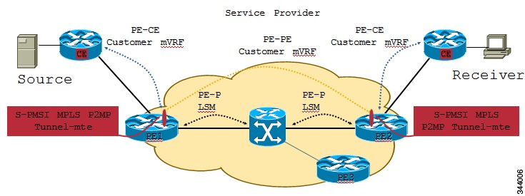
MVPN Static P2MP TE
This feature describes the Multicast VPN (MVPN) support for Multicast over Point-to-Multipoint -Traffic Engineering (P2MP-TE). Currently, Cisco IOS-XR Software supports P2MP-TE only in the Global table and the (S,G) route in the global table can be mapped to P2MP-TE tunnels. However, this feature now enables service providers to use P2MP-TE tunnels to carry VRF multicast traffic. Static mapping is used to map VRF (S, G) traffic to P2MP-TE tunnels, and BGP-AD is used to send P2MP BGP opaque that includes VRF-based P2MP FEC as MDT Selective Provider Multicast Service Interface (S-PMSI).
The advantages of the MVPN support for Multicast over P2MP-TE are:
- Supports traffic engineering such as bandwidth reservation, bandwidth sharing, forwarding replication, explicit routing, and Fast ReRoute (FRR).
- Supports the mapping of multiple multicast streams onto tunnels.
On PE1 router, multicast S,G (video) traffic is received on a VRF interface. The multicast S,G routes are statically mapped to P2MP-TE tunnels. The head-end then originates an S-PMSI (Type-3) BGP-AD route, for each of the S,Gs, with a PMSI Tunnel Attribute (PTA) specifying the P2MP-TE tunnel as the core-tree. The type of the PTA is set to RSVP-TE P2MP LSP and the format of the PTA Tunnel-identifier <Extended Tunnel ID, Reserved, Tunnel ID, P2MP ID>, as carried in the RSVP-TE P2MP LSP SESSION Object. Multiple S,G A-D routes can have the same PMSI Tunnel Attribute.
The tail-end PEs (PE2, PE3) receive and cache these S-PMSI updates (sent by all head-end PEs). If there is an S,G Join present in the VRF, with the Upstream Multicast Hop (UMH) across the core, then the PE looks for an S-PMSI announcement from the UMH. If an S-PMSI route is found with a P2MP-TE PTA, then the PE associates the tail label(s) of the Tunnel, with that VRF. When a packet arrives on the P2MP-TE tunnel, the tail-end removes the label and does an S,G lookup in the 'associated' VRF. If a match is found, the packet is forwarded as per its outgoing information.
BGP 3107 PIC Updates for Global Prefixes
The BGP 3107 PIC Updates for Global Prefixes feature supports Prefix Independent Convergence (PIC) updates for global IPv4 and IPv6 prefixes in an MPLS VPN provider network. This feature is based on RFC 3107 that describes using BGP to distribute MPLS labels for global IPv4 or IPv6 prefixes. This enables IGP to scale better and also provides PIC updates for fast convergence.
RFC 3107 enables routes and labels to be carried in BGP. When BGP is used to distribute a particular route, it can also be used to distribute an MPLS label that is mapped to that route. The label mapping information for a particular route is piggybacked in the same BGP Update message that is used to distribute the route itself. RFC 3107 allows filtering of Next-Hop Loops from OSPF and reduces labels advertised by LDP. This implementation significantly reduces OSPF and LDP database.
The 3107 PIC implementation supports the following address-families with additional-path configuration.
- address-family ipv4 unicast
- address-family ipv6 unicast
- address-family vpnv4 unicast
- address-family vpnv6 unicast
NoteThe address-family l2vpn vpls-vpws does not support additional-path. Hence, the l2vpn service that uses address-family l2vpn vpls-vpws does not guarantee PIC convergence time.
The 3107 PIC implementation supports these Cisco IOS XR features:
- PIC Edge for 3107
- Traffic Engineering Fast-reroute (TE FRR)—Traffic convergence for core link failure is guaranteed within 50 milliseconds using verbatim tunnel.
- L2VPN Service
- L3VPN VPNv4 Service
- 6 PE Service
- 6 VPE Service
- VPLS Service
BGP 3107 PIC Updates for Global Prefixes implementation uses a shared recursive Load Info (RLDI) forwarding object in place of a Light-Weight recursive (LW-RLDI) object. The RLDI is shared between multiple leaves, while the LW-RLDI is instantiated per leaf. Sharing helps in handling PIC updates since it will be prefix independent.
QoS Accounting
Configured Accounting controls the type of overhead and packet length for statistics, policing shaping and queuing. The account option can be specified with a service-policy when applying a policy to an interface. For bundle interfaces, the configured accounting option is applied to all member interfaces.
QPPB on ASR9000 series router
QoS Policy Propagation using Border Gateway Protocol (QPPB) helps to classify packets by QoS Group ID, based on Access control lists (ACLs), Border Gateway Protocol (BGP) community lists, BGP autonomous system (AS) paths, Source Prefix address, or Destination Prefix address. After packet classification, other QoS features such as policing and weighted random early detection (WRED) can be used to specify and enforce policies to fit a specific business model. QPPB also allows the user to map BGP prefixes and attributes to Cisco Express Forwarding (CEF) parameters that can be used to enforce traffic policing.
Packets can be classified based on QoS Group ID and IP precedence in input QOS policy. This is supported on ASR 9000 Ethernet Line cards and Enhanced Ethernet Linecards only. The Cisco IOS XR ASR9000 series router supports QPPBv6.
clear qos counters interface
To clear QoS counters for a specified interface, use the clear qos counters interface command in EXEC mode.
Syntax Description
type
Interface type. For more information, use the question mark (?) online help function.
input
(Optional) Clears input QoS counters that are attached to the specified interface.
output
(Optional) Clears output QoS counters that are attached to the specified interface.
Command History
Release
Modification
Release 3.7.2
This command was introduced.
Release 3.9.0
The interface keyword was added.
Usage Guidelines
The clear qos counters interface command clears all input and output QoS counters that are attached to a specified interface, unless the input or output keyword is specified. If the input or output keyword is specified, only counters attached to the interface in a specified direction are cleared.
The MIB counters are not reset with this command.
Task ID
This example shows how to clear QoS counters attached to Gigabit Ethernet interface 0/1/0/9:RP/0/RSP0/CPU0:router# clear qos counters interface gigabitethernet 0/1/0/9This example shows how to clear output QoS counters attached to POS interface 0/7/0/3:RP/0/RSP0/CPU0:router# clear qos counters interface pos 0/7/0/3 outputDestination-based NetFlow Accounting
Destination-based NetFlow accounting (DBA) is a usage-based billing application that tracks and records traffic according to its destination and enables service providers to do destination-specific accounting and billing. The destination-based NetFlow accounting record includes the destination peer autonomous system (AS) number and the BGP next-hop IP address.
DBA is supported on ASR9000 Gigabit Ethernet and ASR9000 Enhanced Gigabit Ethernet linecards.
In destination-based NetFlow accounting, these fields are collected and exported:
- Destination peer AS number
- BGP next-hop IP address
- Ingress interface
- Egress interface
- Forwarding status
- Incoming IPv4 TOS
- Counter of packets in the flow
- Counter of bytes in the flow
- Timestamp for the first and last packets in the flow
Destination-based NetFlow accounting supports these features:
- Only IPv4 addresses
- Configuration on physical interfaces, bundle interfaces, and logical subinterfaces
- IPv4 unicast and multicast traffic
- Only ingress traffic
- Only full mode NetFlow
- NetFlow export format Version 9 over User Datagram Protocols (UDPs)
Destination-based NetFlow accounting does not support these features :
- IPv6 addresses
- MPLS IPv4 and IPv6
- Configuration for individual Modular QoS Command-Line Interface (MQC) classes
- Simultaneous configuration of destination-based NetFlow accounting with IPv4 sampled NetFlow on the same interface, in the same direction.
- Layer 2 switched MPLS traffic
- Egress traffic
- Sampled mode NetFlow
- NetFlow export formats version 5, version 8, IP Flow Information Export (IPFIX), or Stream Control Transmission Protocol (SCTP).
Overview of Satellite nV Switching System
The Cisco ASR 9000 Series Router Satellite Network Virtualization (nV) service or the Satellite Switching System enables you to configure a topology in which one or more satellite switches complement one or more Cisco ASR 9000 Series routers to collectively realize a single virtual switching system. In this system, the satellite switches act under the management control of the Cisco ASR 9000 Series Aggregation Services Routers.
Interconnection between the Cisco ASR 9000 Series Router and its satellite switches is through standard ethernet interfaces. These are typically 10 Gigabit Ethernet initially but not restricted to any particular flavor or line speed of ethernet.
This type of architecture can be realized in a carrier Ethernet transport network with the satellite switches used as either access switches or pre-aggregation and aggregation switches feeding into an edge switch such as the Cisco ASR 9000 Series Router or Cisco CRS-3 Router where more advanced L2, L3 services are provisioned.
For more information on the Satellite nV Switching System, refer to the Cisco ASR 9000 Series Aggregation Services Router Interface and Hardware Component Configuration Guide.
Overview of Cisco ASR 9000 nV Edge Architecture
A Cisco ASR 9000 Series Cluster consists of two or more Cisco ASR 9000 Series Router chassis that are combined to form a single logical switching or routing entity. In Cisco IOS XR Software Release 4.2.1, the scalability of a cluster is limited to two chassis. However, it can have more than two chassis in future releases.
For more information on this feature, refer to the Cisco ASR 9000 Series Aggregation Services Router Interface and Hardware Component Configuration Guide.
BFD for Multihop Paths
BFD multihop (BFD-MH) is a BFD session between two addresses that are not on the same subnet. An example of BFD-MH is a BFD session between PE and CE loopback addresses or BFD sessions between routers that are several TTL hops away. The applications that support BFD multihop are external and internal BGP. BFD multihop supports BFD on arbitrary paths, which can span multiple network hops.
The BFD Multihop feature provides sub-second forwarding failure detection for a destination more than one hop, and up to 255 hops. The bfd multihop ttl-drop-threshold command can be used to drop BFD packets coming from neighbors exceeding a certain number of hops. BFD multihop is supported on all currently supported media-type for BFD singlehop. BFD-MH is supported on A9K-SIP-700 line card in Cisco IOS XR Software Release 4.2.1.
Layer 2 Features Supported on ATM Interfaces
ATM is a cell-switching and multiplexing technology that is widely used in Wide Area Networks (WANs). ATM protocol standards enable point-to-point, point-to-multipoint, and broadcast services connections using various slow- and high-speed network media. Connectivity between two ATM permanent virtual circuits (PVCs) is established using ATM signaling mechanisms.
- Layer 2 VPN on ATM Interfaces The Layer 2 VPN (L2VPN) feature enables the connection between different types of Layer 2 attachment circuits and pseudowires, allowing users to implement different types of end-to-end services. Cisco IOS XR software supports a point-to-point, end-to-end service, where two ATM ACs are connected together. Switching can take place in two ways:
- VC-Class Mapping A virtual circuit (VC) class enables the configuration of VC parameters that are then mapped to a main interface, subinterface, or PVC. Without vc-classes, you must perform considerable manual configuration on each ATM main interface, subinterface, and PVC and on the router. This configuration can be time consuming and error prone. After you have created vc-class, you can apply that vc-class to as many ATM interfaces, subinterfaces, or PVCs as you want.
- F5 OAM on ATM Interfaces The F5 Operation, Administration, and Maintenance (OAM) feature performs fault-management and performance-management functions on PVCs. If the F5 OAM feature is not enabled on a PVC, then that PVC remains up on the end device in the event of a service disruption where network connectivity is lost. The result is that routing entries that point to the connection remain in the routing table and, therefore, packets are lost. The F5 OAM feature detects such failures and brings the PVC down if there is a disruption along its path.
Frame Relay Network to Network Support (FR-NNI)
The Network to Network Interface (NNI) is designed to provide an efficient interface between two frame relay sub-networks or like where network equipment is required to interact between two independent Frame Relay networks.
UNI LMI type (DTE/DCE) modes are one sided in nature. The task for generating the Status Enquiry message is that of the user end/DTE end and similarly the task for the corresponding STATUS message is that of the network/DCE end. This may be good for many applications, but a balanced protocol is preferable, so that a legitimate symmetry is held between the two sides of the interface and each side can preserve the state of availability(pvc's) of the other end.This is achieved in NNI by its bidirectional procedures.
The kind of bidirectional procedures in NNI differs in only one method to that from the UNI. The Status Enquiry message is issued from both sides of the interface, and their corresponding Status message response is also generated from both sides. Hence in NNI, both sides of the FR interfaces behave in the manner of both the user(DTE) and the network(DCE) and by this balance neither side will be considered as 'user' end.
To make a frame relay encapsulated interface to work in NNI interface mode, use the command frame-relay intf-type nni.
BGP Prefix Origin Validation Based on RPKI
A BGP route associates an address prefix with a set of autonomous systems (AS) that identify the interdomain path the prefix has traversed in the form of BGP announcements. This set is represented as the AS_PATH attribute in BGP and starts with the AS that originated the prefix.
To help reduce well-known threats against BGP including prefix mis-announcing and monkey-in-the-middle attacks, one of the security requirements is the ability to validate the origination AS of BGP routes. The AS number claiming to originate an address prefix (as derived from the AS_PATH attribute of the BGP route) needs to be verified and authorized by the prefix holder.
The Resource Public Key Infrastructure (RPKI) is an approach to build a formally verifiable database of IP addresses and AS numbers as resources. The RPKI is a globally distributed database containing, among other things, information mapping BGP (internet) prefixes to their authorized origin-AS numbers. Routers running BGP can connect to the RPKI to validate the origin-AS of BGP paths.
BGP Prefix Independent Convergence for RIB and FIB
BGP PIC for RIB and FIB adds support for static recursive as PE-CE and faster backup activation by using fast re-route trigger.
The BGP PIC for RIB and FIB feature supports:
- FRR-like trigger for faster PE-CE link down detection, to further reduce the convergence time (Fast PIC-edge activation).
- PIC-edge for static recursive routes.
- BFD single-hop trigger for PIC-Edge without any explicit /32 static route configuration.
- Recursive PIC activation at third level and beyond, on failure trigger at the first (IGP) level.
- BGP path recursion constraints in FIB to ensure that FIB is in sync with BGP with respect to BGP next-hop resolution.
OSPF SPF Prefix Prioritization
The OSPF SPF Prefix Prioritization feature enables an administrator to converge, in a faster mode, important prefixes during route installation.
When a large number of prefixes must be installed in the Routing Information Base (RIB) and the Forwarding Information Base (FIB), the update duration between the first and last prefix, during SPF, can be significant.
In networks where time-sensitive traffic (for example, VoIP) may transit to the same router along with other traffic flows, it is important to prioritize RIB and FIB updates during SPF for these time-sensitive prefixes.
The OSPF SPF Prefix Prioritization feature provides the administrator with the ability to prioritize important prefixes to be installed, into the RIB during SPF calculations. Important prefixes converge faster among prefixes of the same route type per area. Before RIB and FIB installation, routes and prefixes are assigned to various priority batch queues in the OSPF local RIB, based on specified route policy. The RIB priority batch queues are classified as "critical," "high," "medium," and "low," in the order of decreasing priority.
When enabled, prefix alters the sequence of updating the RIB with this prefix priority:
Critical > High > Medium > Low
As soon as prefix priority is configured, /32 prefixes are no longer preferred by default; they are placed in the low-priority queue, if they are not matched with higher-priority policies. Route policies must be devised to retain /32s in the higher-priority queues (high-priority or medium-priority queues).
Priority is specified using route policy, which can be matched based on IP addresses or route tags. During SPF, a prefix is checked against the specified route policy and is assigned to the appropriate RIB batch priority queue.
These are examples of this scenario:
- If only high-priority route policy is specified, and no route policy is configured for a medium priority:
- If both high-priority and medium-priority route policies are specified, and no maps are specified for critical priority:
- If both critical-priority and high-priority route policies are specified, and no maps are specified for medium priority:
- If only medium-priority route policy is specified and no maps are specified for high priority or critical priority:
Use the [no] spf prefix-priority route-policy rpl command to prioritize OSPF prefix installation into the global RIB during SPF. SPF prefix prioritization is disabled by default. In disabled mode, /32 prefixes are installed into the global RIB, before other prefixes. If SPF prioritization is enabled, routes are matched against the route-policy criteria and are assigned to the appropriate priority queue based on the SPF priority set. Unmatched prefixes, including /32s, are placed in the low-priority queue. If all /32s are desired in the high-priority queue or medium-priority queue, configure this single route map:
- Permitted prefixes matching medium-priority route policy are assigned to a medium-priority queue.
- Unmatched prefixes, including /32s, are placed in a low-priority queue.
prefix-set ospf-medium-prefixes
  0.0.0.0/0 ge 32
  end-set
Management Information Base (MIB) for OSPFv3
Cisco IOS XR supports full MIBs and traps for OSPFv3, as defined in RFC 5643. The RFC 5643 defines objects of the Management Information Base (MIB) for use with the Open Shortest Path First (OSPF) Routing Protocol for IPv6 ( OSPF version 3).
The OSPFv3 MIB implementation is based on the IETF draft Management Information Base for OSPFv3 ( draft-ietf-ospf-ospfv3-mib-8). Users need to update the NMS application to pick up the new MIB when upgraded to RFC 5643.
Refer to the Cisco ASR 9000 Series Aggregation Services Router MIB Specification Guide for more information on Cisco IOS XR MIB support.
Nested Wildcard Apply Policy
The hierarchical constructs of Routing Policy Language (RPL) allows one policy to refer to another policy. The referred or called policy is known as a child policy. The policy from which another policy is referred is called calling or parent policy. A calling or parent policy can nest multiple child policies for attachment to a common set of BGP neighbors. The nested wildcard apply policy allows wildcard (*) based apply nesting. The wildcard operation permits declaration of a generic apply statement that calls all policies that contain a specific defined set of alphanumeric characters, defined on the router.
A wildcard is specified by placing an asterisk (*) at the end of the policy name in an apply statement. Passing parameters to wildcard policy is not supported. The wildcard indicates that any value for that portion of the apply policy matches.
To illustrate nested wildcard apply policy, consider this policy hierarchy:route-policy Nested_Wilcard apply service_policy_customer* end-policy route-policy service_policy_customer_a if destination in prfx_set_customer_a then set extcommunity rt (1:1) additive endif end-policy route-policy service_policy_customer_b if destination in prfx_set_customer_b then set extcommunity rt (1:1) additive endif end-policy route-policy service_policy_customer_c if destination in prfx_set_customer_c then set extcommunity rt (1:1) additive endif end-policyHere, a single parent apply statement (apply service_policy_customer*) calls (inherits) all child polices that contain the identified character string "service_policy_customer". As each child policy is defined globally, the parent dynamically nests the child policies based on the policy name. The parent is configured once and inherits each child policy on demand. There is no direct association between the parent and the child policies beyond the wildcard match statement.
8000 VRF Support on ASR 9000 Enhanced Ethernet Line Card
The ASR 9000 Enhanced Ethernet Line Card supports a maximum number of 8190 VRFs. The increase is from 4095 VRFs. To enable the maximum number of VRFs, use the hw-module vrf scale extended command in admin configuration mode. After enabling this command, reload the router for the command to take effect.
NoteThis feature will work only when all the line cards in the system are ASR 9000 Enhanced Ethernet Line Card (NP4C based).
8000 BFD Sessions Support on ASR 9000 Enhanced Ethernet LC
The 8000 BFD Sessions Support on ASR 9000 Enhanced Ethernet LC feature enhances the BFD single hop scale support on ASR 9000 Enhanced Ethernet line cards from 4000 to 8000 sessions at 500ms x 3. Accordingly, the policer rates are modified as:
InterAS Support on Multicast VPN
The Multicast VPN Inter-AS Support feature enables service providers to provide multicast connectivity to VPN sites that span across multiple autonomous systems. This feature enables Multicast Distribution Trees (MDTs), used for Multicast VPNs (MVPNs), to span multiple autonomous systems.
There are two types of MVPN inter-AS deployment scenarios:
- Single-Provider Inter-AS—A service provider whose internal network consists of multiple autonomous systems.
- Intra-Provider Inter-AS—Multiple service providers that need to coordinate their networks to provide inter-AS support.
To establish a Multicast VPN between two autonomous systems, a MDT-default tunnel must be setup between the two PE routers. The PE routers accomplish this by joining the configured MDT-default group. This MDT-default group is configured on the PE router and is unique for each VPN. The PIM sends the join based on the mode of the groups, which can be PIM SSM, or sparse mode.
For more information about the InterAS Support on MVPN, see the Cisco ASR 9000 Series Aggregation Services Router Multicast Configuration Guide.
Enhanced Object Tracking for HSRP and IP Static
A failure between the active router and the core network cannot be detected using standard HSRP failure detection mechanisms. Object tracking is used to detect such failures. When such a failure occurs, the active router applies a priority decrement to its HSRP session. If this causes its priority to fall below that of the standby router, it will detect this from the HSRP control traffic, and then use this as a trigger to preempt and take over the active role.
The enhanced object tracking for HSRP and IP Static feature provides first-hop redundancy as well as default gateway selection based on IP Service Level Agreement (IPSLA).
See the Cisco ASR 9000 Series Aggregation Services Router Routing Configuration Guide, for more information about enhanced object tracking for static routes.
ABF on GRE tunnel interface
ACL based forwarding (ABF) has been enabled for Generic Routing Encapsulation (GRE) tunnel interfaces for Release 4.2.1. ABFv4/ABFv6 for GRE tunnel interface is supported for the A9K-SIP-700 and ASR 9000 Enhanced Ethernet line cards. When ACL is configured under GRE tunnel, the incoming IPv4/IPv6 traffic will be subjected to egress ACL on the encap router. On the decap router de-capsulated packet will be processed using ingress ACL. For the ASR 9000 Enhanced Ethernet line card, ABFv4 is supported; ABFv6 is not supported. About two thousand ACLs per box are supported for GRE tunnels.
Note
The following cards do not support ABF on GRE tunnel interface:
- 2-Port 10-Gigabit Ethernet, 20-Port Gigabit Ethernet Combination Line Cards (A9K-2T20GE-B and A9K-2T20GE-L)
- 4-Port 10-Gigabit Ethernet Line Cards (A9K-4T-B, -E, -L)
- 8-Port 10-Gigabit Ethernet DX Line Cards (A9K-8T/4-B, -E, -L)
- 8-Port 10-Gigabit Ethernet Line Cards (A9K-8T-B, -E, -L)
- 16-Port 10-Gigabit Ethernet Line Cards (A9K-16T/8-B, -E, -L)
- 40-Port Gigabit Ethernet Line Cards (A9K-40GE-B, -E, -L)
IPv4/IPv6 Forwarding over GRE Tunnels
Packets that are tunneled over GRE tunnels enter the router as normal IP packets. The packets are forwarded (routed) using the destination address of the IP packet. In the case of Equal Cost Multi Path (ECMP) scenarios, an output interface-adjacency is selected, based on a platform-specific L3 load balance (LB) hash. Once the egress physical interface is known, the packet is sent out of that interface, after it is first encapsulated with GRE header followed by the L2 rewrite header of the physical interface. After the GRE encapsulated packet reaches the remote tunnel endpoint router, the GRE packet is decapsulated. The destination address lookup of the outer IP header (this is the same as the tunnel destination address) will find a local address (receive) entry on the ingress line card.
The first step in GRE decapsulation is to qualify the tunnel endpoint, before admitting the GRE packet into the router, based on the combination of tunnel source (the same as source IP address of outer IP header) and tunnel destination (the same as destination IP address of outer IP header). If the received packet fails tunnel admittance qualification check, the packet is dropped by the decapsulation router. On successful tunnel admittance check, the decapsulation strips the outer IP and GRE header off the packet, then starts processing the inner payload packet as a regular packet.
When a tunnel endpoint decapsulates a GRE packet, which has an IPv4/IPv6 packet as the payload, the destination address in the IPv4/IPv6 payload packet header is used to forward the packet, and the TTL of the payload packet is decremented. Care should be taken when forwarding such a packet. If the destination address of the payload packet is the encapsulator of the packet (that is the other end of the tunnel), looping can occur. In such a case, the packet must be discarded.
IPv4/IPv6 ACL over BVI interface
In Release 4.2.1, IPv4/IPv6 ACL is enabled over BVI interfaces on the ASR 9000 Enhanced Ethernet Line Cards.
For ACL over BVI interfaces, the defined direction is:On the A9K-SIP-700 and ASR 9000 Ethernet Line Cards, ACLs on BVI interfaces are not supported.
NoteFor ASR 9000 Ethernet linecards, ACL can be applied on the EFP level (IPv4 L3 ACL can be applied on an L2 interface).
IPv6 ACL in Class Map
In Release 4.2.1, Quality of Service (Qos) features on ASR 9000 Ethernet line card and ASR 9000 Enhanced Ethernet line card are enhanced to support these:DS-Lite on ISM
Cisco IOS XR Software Release 4.2.1 introduces support for the Dual Stack Lite (DS-Lite) feature on the ISM line card. The Dual Stack Lite feature provides a means for IPv4 hosts to access both IPv4 and IPv6 networks.
- Dual Stack Lite Feature Configuration The Dual Stack Lite feature provides a means for IPv4 hosts to access both IPv4 and IPv6 networks. Also, IPv4 hosts may need to access IPv4 internet over an IPv6 access network. The IPv4 hosts will have private addresses which need to have network address translation (NAT) completed before reaching the IPv4 internet. The Dual Stack Lite feature helps in these cases, by:
IPv6 traffic from the CPE device is natively forwarded.
- Tunnelling IPv4 packets from CE devices over IPv6 tunnels to the CGSE blade.
- Decapsulating the IPv4 packet and sending the decapsulated content to the IPv4 internet after completing network address translation (sometimes called NATing).
- In the reverse direction completing reverse-network address translation (sometimes called reverse-NATing) and then tunnelling them over IPv6 tunnels to the CPE device.
The following sections show Dual Stack Lite configuration examples assuming the inside and outside network are in default vrf:
NoteThe number of dual stack lite (DS-Lite) instances supported on the ISM line card is 64.
- Service Virtual Interface and Service Location Configuration
hw-module service cgn location 0/6/CPU0 interface ServiceInfra1 ipv4 address 55.55.55.55 255.255.255.240 service-location 0/6/CPU0 interface ServiceApp1 ipv6 address 1100::1/122 service cgn cgn1 service-type ds-lite interface ServiceApp2 ipv4 address 209.0.0.1 255.255.255.240 service cgn cgn1 service-type ds-lite- CGN Instance Configuration
NoteThe maximum number of DS Lite instances that can be created under a CGN instance on a given ISM line card is 64.
service cgn cgn1 service-type ds-lite dslite1 external-logging syslog server address 25.25.25.1 port 514 map address-pool 150.0.1.0/24 aftr-tunnel-endpoint-address 1001::1001 address-family ipv4 interface ServiceApp2 address-family ipv6 interface ServiceApp1 protocol udp session active timeout 600 session init timeout 600 protocol tcp session active timeout 300 session init timeout 300 protocol icmp timeout 180- Static Route Configuration to Direct Traffic Towards ISM
router static address-family ipv4 unicast 150.0.1.0/24 ServiceApp2 router static address-family ipv6 unicast 1001::1001/128 ServiceApp1- DS-Lite Scale and Performance for ISM
DS-Lite feature pulls translation entries from the same pool as the NAT44 feature. Because of this the scale of the DS-Lite feature will be same as the scale of the NAT44 feature.
- DS-Lite and NAT44 together support a total of 20 million sessions.
- The total number of unique users behind B4 router basically (IPv6 Source, IPv4 Source) tuple can scale to 1 million (which is same as NAT44 scale).
- There is no real limit to the number of B4 routers and their associated tunnels connecting to the AFTR, except the session limit - 20 million B4 routers (assuming each router has only one session). In reality, a maximum of 1 million B4 routers can connect to an AFTR at any given time.
- The performance of DS-Lite traffic will be similar to that of NAT44 traffic - combined IPv4 and IPv6 traffic will be 10 Gbps for IMIX traffic.
- Verifying the Dual Stack Lite Software Packages
This section describes the following three commands that are used to verify IOS XR software version and active packages:For more information, refer to the Cisco ASR 9000 Series Aggregation Services Router System Management Command Reference, Release 4.2.1 and the Cisco ASR 9000 Series Aggregation Services Router System Management Configuration Guide, Release 4.2.1 online.
- show version This command is used to displays a variety of system information, including hardware and software version, router uptime, boot settings (configuration register), and active software. Sample Output:
RP/0/RSP0/CPU0:VKG#show version Cisco IOS XR Software, Version 4.2.1.03I[Default] Copyright (c) 2011 by Cisco Systems, Inc. ROM: System Bootstrap, Version 1.05(20101118:025914) [ASR9K ROMMON], ERISTOFF uptime is 1 day, 8 hours, 13 minutes System image file is "bootflash:disk0/asr9k-os-mbi-4.2.1.03I/0x100000/mbiasr9k-rp.vm" cisco ASR9K Series (MPC8641D) processor with 4194304K bytes of memory. MPC8641D processor at 1333MHz, Revision 2.2 ASR-9010 AC Chassis 4 Management Ethernet 60 GigabitEthernet 12 TenGigE 12 DWDM controller(s) 12 WANPHY controller(s) 219k bytes of non-volatile configuration memory. 977M bytes of compact flash card. 67988M bytes of hard disk. 1605616k bytes of disk0: (Sector size 512 bytes). 1605616k bytes of disk1: (Sector size 512 bytes). Configuration register on node 0/RSP0/CPU0 is 0x102 Boot device on node 0/RSP0/CPU0 is disk0: Package active on node 0/RSP0/CPU0: iosxr-ce, V 4.2.1.03I[1n_11.10.26], Cisco Systems, at disk0:iosxr-ce-4.2.1.03I Built on Wed Oct 26 17:26:00 UTC 2011 By bgl-lds-181 in /auto/roddick-cgn-nightly/nightly/dslite_421_bf/nightly/dslite-421-bugfix_dslite-421-bugfix_1_Wed for pie asr9k-service-supp, V 4.2.1.03I[1n_11.10.26], Cisco Systems, at disk0:asr9k-service-supp-4.2.1.03I Built on Wed Oct 26 18:22:50 UTC 2011 By bgl-lds-181 in /auto/roddick-cgn-nightly/nightly/dslite_421_bf/nightly/dslite-421-bugfix_dslite-421-bugfix_1_Wed for pie asr9k-fwding, V 4.2.1.03I[1n_11.10.26], Cisco Systems, at disk0:asr9k-fwding-4.2.1.03I Built on Wed Oct 26 17:26:00 UTC 2011 By bgl-lds-181 in /auto/roddick-cgn-nightly/nightly/dslite_421_bf/nightly/dslite-421-bugfix_dslite-421-bugfix_1_Wed for pie asr9k-fwding-4.2.1.03I.CSCts54905, V 1.0.0[SMU], Cisco Systems, at disk0:asr9k-fwding-4.2.1.03I.CSCts54905-1.0.0 Built on Thu Oct 27 10:53:34 UTC 2011 By bgl-lds-160 in /nobackup/srinud/dslite-421-bugfix-cgn-EFR-00000173895 for pie asr9k-cpp, V 4.2.1.03I[1n_11.10.26], Cisco Systems, at disk0:asr9k-cpp-4.2.1.03I Built on Wed Oct 26 17:26:02 UTC 2011 By bgl-lds-181 in /auto/roddick-cgn-nightly/nightly/dslite_421_bf/nightly/dslite-421-bugfix_dslite-421-bugfix_1_Wed for pie asr9k-ce, V 4.2.1.03I[1n_11.10.26], Cisco Systems, at disk0:asr9k-ce-4.2.1.03I Built on Wed Oct 26 17:26:02 UTC 2011 By bgl-lds-181 in /auto/roddick-cgn-nightly/nightly/dslite_421_bf/nightly/dslite-421-bugfix_dslite-421-bugfix_1_Wed for pie asr9k-scfclient, V 4.2.1.03I[1n_11.10.26], Cisco Systems, at disk0:asr9k-scfclient-4.2.1.03I Built on Wed Oct 26 17:26:00 UTC 2011 By bgl-lds-181 in /auto/roddick-cgn-nightly/nightly/dslite_421_bf/nightly/dslite-421-bugfix_dslite-421-bugfix_1_Wed for pie iosxr-service, V 4.2.1.03I[1n_11.10.26], Cisco Systems, at disk0:iosxr-service-4.2.1.03I Built on Wed Oct 26 18:22:50 UTC 2011 By bgl-lds-181 in /auto/roddick-cgn-nightly/nightly/dslite_421_bf/nightly/dslite-421-bugfix_dslite-421-bugfix_1_Wed for pie iosxr-mpls, V 4.2.1.03I[1n_11.10.26], Cisco Systems, at disk0:iosxr-mpls-4.2.1.03I Built on Wed Oct 26 17:57:02 UTC 2011 By bgl-lds-181 in /auto/roddick-cgn-nightly/nightly/dslite_421_bf/nightly/dslite-421-bugfix_dslite-421-bugfix_1_Wed for pie iosxr-mgbl, V 4.2.1.03I[1n_11.10.26], Cisco Systems, at disk0:iosxr-mgbl-4.2.1.03I Built on Wed Oct 26 17:45:34 UTC 2011 By bgl-lds-181 in /auto/roddick-cgn-nightly/nightly/dslite_421_bf/nightly/dslite-421-bugfix_dslite-421-bugfix_1_Wed for pie iosxr-mcast, V 4.2.1.03I[1n_11.10.26], Cisco Systems, at disk0:iosxr-mcast-4.2.1.03I Built on Wed Oct 26 18:10:41 UTC 2011 By bgl-lds-181 in /auto/roddick-cgn-nightly/nightly/dslite_421_bf/nightly/dslite-421-bugfix_dslite-421-bugfix_1_Wed for pie iosxr-routing, V 4.2.1.03I[1n_11.10.26], Cisco Systems, at disk0:iosxr-routing-4.2.1.03I Built on Wed Oct 26 17:26:00 UTC 2011 By bgl-lds-181 in /auto/roddick-cgn-nightly/nightly/dslite_421_bf/nightly/dslite-421-bugfix_dslite-421-bugfix_1_Wed for pie iosxr-infra, V 4.2.1.03I[1n_11.10.26], Cisco Systems, at disk0:iosxr-infra-4.2.1.03I Built on Wed Oct 26 17:26:00 UTC 2011 By bgl-lds-181 in /auto/roddick-cgn-nightly/nightly/dslite_421_bf/nightly/dslite-421-bugfix_dslite-421-bugfix_1_Wed for pie iosxr-fwding, V 4.2.1.03I[1n_11.10.26], Cisco Systems, at disk0:iosxr-fwding-4.2.1.03I Built on Wed Oct 26 17:26:00 UTC 2011 By bgl-lds-181 in /auto/roddick-cgn-nightly/nightly/dslite_421_bf/nightly/dslite-421-bugfix_dslite-421-bugfix_1_Wed for pie iosxr-diags, V 4.2.1.03I[1n_11.10.26], Cisco Systems, at disk0:iosxr-diags-4.2.1.03I Built on Wed Oct 26 17:26:00 UTC 2011 By bgl-lds-181 in /auto/roddick-cgn-nightly/nightly/dslite_421_bf/nightly/dslite-421-bugfix_dslite-421-bugfix_1_Wed for pie asr9k-fpd, V 4.2.1.03I[1n_11.10.26], Cisco Systems, at disk0:asr9k-fpd-4.2.1.03I Built on Wed Oct 26 17:26:02 UTC 2011 By bgl-lds-181 in /auto/roddick-cgn-nightly/nightly/dslite_421_bf/nightly/dslite-421-bugfix_dslite-421-bugfix_1_Wed for pie asr9k-diags-supp, V 4.2.1.03I[1n_11.10.26], Cisco Systems, at disk0:asr9k-diags-supp-4.2.1.03I Built on Wed Oct 26 17:26:00 UTC 2011 By bgl-lds-181 in /auto/roddick-cgn-nightly/nightly/dslite_421_bf/nightly/dslite-421-bugfix_dslite-421-bugfix_1_Wed for pie asr9k-mgbl-supp, V 4.2.1.03I[1n_11.10.26], Cisco Systems, at disk0:asr9k-mgbl-supp-4.2.1.03I Built on Wed Oct 26 17:45:34 UTC 2011 By bgl-lds-181 in /auto/roddick-cgn-nightly/nightly/dslite_421_bf/nightly/dslite-421-bugfix_dslite-421-bugfix_1_Wed for pie asr9k-mcast-supp, V 4.2.1.03I[1n_11.10.26], Cisco Systems, at disk0:asr9k-mcast-supp-4.2.1.03I Built on Wed Oct 26 18:10:41 UTC 2011 By bgl-lds-181 in /auto/roddick-cgn-nightly/nightly/dslite_421_bf/nightly/dslite-421-bugfix_dslite-421-bugfix_1_Wed for pie asr9k-base, V 4.2.1.03I[1n_11.10.26], Cisco Systems, at disk0:asr9k-base-4.2.1.03I Built on Wed Oct 26 17:26:00 UTC 2011 By bgl-lds-181 in /auto/roddick-cgn-nightly/nightly/dslite_421_bf/nightly/dslite-421-bugfix_dslite-421-bugfix_1_Wed for pie asr9k-os-mbi, V 4.2.1.03I[1n_11.10.26], Cisco Systems, at disk0:asr9k-os-mbi-4.2.1.03I Built on Wed Oct 26 17:27:09 UTC 2011 By bgl-lds-181 in /auto/roddick-cgn-nightly/nightly/dslite_421_bf/nightly/dslite-421-bugfix_dslite-421-bugfix_1_Wed for pie- show install active summary This command is used to display active software packages. Verify that the command output matches the output of the show install committed command. If the output does not match, when you reload the router, the software displayed in the show install committed command output is the software that will be loaded. Sample Output:
RP/0/RSP0/CPU0:VKG#show install active summary Active Packages: disk0:asr9k-services-p-4.2.1.03I disk0:asr9k-mini-p-4.2.1.03I disk0:asr9k-mpls-p-4.2.1.03I disk0:asr9k-mgbl-p-4.2.1.03I disk0:asr9k-mcast-p-4.2.1.03I- show install committed This command is used to display committed software packages. The committed software packages are the software packages that will be booted on a router reload. Sample Output:
RP/0/RSP0/CPU0:VKG#show install committed Node 0/RSP0/CPU0 [RP] [SDR: Owner] Boot Device: disk0: Boot Image: /disk0/asr9k-os-mbi-4.2.1.03I/0x100000/mbiasr9k-rp.vm Committed Packages: disk0:asr9k-services-p-4.2.1.03I disk0:asr9k-mini-p-4.2.1.03I disk0:asr9k-mpls-p-4.2.1.03I disk0:asr9k-mgbl-p-4.2.1.03I disk0:asr9k-mcast-p-4.2.1.03I Node 0/RSP1/CPU0 [RP] [SDR: Owner] Boot Device: disk0: Boot Image: /disk0/asr9k-os-mbi-4.2.1.03I/0x100000/mbiasr9k-rp.vm Committed Packages: disk0:asr9k-services-p-4.2.1.03I disk0:asr9k-mini-p-4.2.1.03I disk0:asr9k-mpls-p-4.2.1.03I disk0:asr9k-mgbl-p-4.2.1.03I disk0:asr9k-mcast-p-4.2.1.03I Node 0/0/CPU0 [LC] [SDR: Owner] Boot Device: mem: Boot Image: /disk0/asr9k-os-mbi-4.2.1.03I/lc/mbiasr9k-lc.vm Committed Packages: disk0:asr9k-services-p-4.2.1.03I disk0:asr9k-mini-p-4.2.1.03I disk0:asr9k-mpls-p-4.2.1.03I disk0:asr9k-mcast-p-4.2.1.03I Node 0/2/CPU0 [LC] [SDR: Owner] Boot Device: mem: Boot Image: /disk0/asr9k-os-mbi-4.2.1.03I/lc/mbiasr9k-lc.vm Committed Packages: disk0:asr9k-services-p-4.2.1.03I disk0:asr9k-mini-p-4.2.1.03I disk0:asr9k-mpls-p-4.2.1.03I disk0:asr9k-mcast-p-4.2.1.03I Node 0/4/CPU0 [LC] [SDR: Owner] Boot Device: mem: Boot Image: /disk0/asr9k-os-mbi-4.2.1.03I/lc/mbiasr9k-lc.vm Committed Packages: disk0:asr9k-services-p-4.2.1.03I disk0:asr9k-mini-p-4.2.1.03I disk0:asr9k-mpls-p-4.2.1.03I disk0:asr9k-mcast-p-4.2.1.03I Node 0/5/CPU0 [LC] [SDR: Owner] Boot Device: mem: Boot Image: /disk0/asr9k-os-mbi-4.2.1.03I/lc/mbiasr9k-lc.vm Committed Packages: disk0:asr9k-services-p-4.2.1.03I disk0:asr9k-mini-p-4.2.1.03I disk0:asr9k-mpls-p-4.2.1.03I disk0:asr9k-mcast-p-4.2.1.03I Node 0/6/CPU0 [LC] [SDR: Owner] Boot Device: mem: Boot Image: /disk0/asr9k-os-mbi-4.2.1.03I/lc/mbiasr9k-lc.vm Committed Packages: disk0:asr9k-services-p-4.2.1.03I disk0:asr9k-mini-p-4.2.1.03I disk0:asr9k-mpls-p-4.2.1.03I disk0:asr9k-mcast-p-4.2.1.03I- Verifying the Line Card Status and FPD This section describes the following three commands that are used to verify the line status and to display field-programmable device (FPD) compatibility for all modules or a specific module:
For more information, refer to the Cisco ASR 9000 Series Aggregation Services Router System Management Command Reference, Release 4.2.1 and the Cisco ASR 9000 Series Aggregation Services Router System Management Configuration Guide, Release 4.2.1 online.
- show platform This command is used to displays information about the status of cards and modules installed in the router. Sample Output:
RP/0/RSP0/CPU0:VKG#show platform Node Type State Config State ----------------------------------------------------------------------------- 0/RSP0/CPU0 A9K-RSP-4G(Active) IOS XR RUN PWR,NSHUT,MON 0/RSP1/CPU0 A9K-RSP-4G(Standby) IOS XR RUN PWR,NSHUT,MON 0/0/CPU0 A9K-40GE-E IOS XR RUN PWR,NSHUT,MON 0/4/CPU0 A9K-8T/4-E IOS XR RUN PWR,NSHUT,MON 0/5/CPU0 A9K-4T-B IOS XR RUN PWR,NSHUT,MON 0/6/CPU0 A9K-ISM-100(LCP) IOS XR RUN PWR,NSHUT,NMON 0/6/CPU1 A9K-ISM-100(SE) APP-READY RP/0/RSP0/CPU0:VKG#- show platform summary location <ism_loc> Use this command to get the CGv6 Application version and status. Sample Output:
RP/0/RSP0/CPU0:VKG#show platform summary location 0/6/cpu0 -------------------------------------------------------- Platform Node : 0/6/CPU0 (slot 8) PID : A9K-SIM-100 Card Type : Integrated Services Module VID/SN : N/A / FHH1415002L Oper State : IOS XR RUN Last Reset : Shutdown due to unknown reason : Wed Nov 2 23:00:27 2011 Configuration : Power is enabled Bootup enabled. Monitoring Disabled Rommon Ver : Version 1.2(20091201:235620) IOS SW Ver : 0.0.55 Main Power : Power state Enabled. Estimate power 630 Watts of power required. Faults : N/A ------------------------------------------------------------------ Platform Node : 0/6/CPU1 (slot 8) Card Type : Integrated Services Module (Service Engine) Oper State : APP-READY Last Reset : Unknown Last Failure : Unknown Last Start Time : Wed Nov 2 23:02:53 2011 Last Ready Time : N/A Uptime : 00:00:00 BIOS Ver : 0.17 (Thurley.3.60.18.0033) SW Ver : 1.0.1.0 (Built on Oct 31, 2011, from services/cgn@main51/37) App Status : 8 CGv6 Application instance(s) is/are running ------------------------------------------------------------------ RP/0/RSP0/CPU0:VKG#- show hw-module fpd location <ism_loc> Use this command to check the current version of field-programmable gate arrays (FPGAs) in your ISM card. Use the upgrade hw-module fpd command to upgrade the FPD image on ISM. Sample Output:
RP/0/RSP0/CPU0:VKG(admin)#show hw-module fpd location 0/6/CPU0 ==================================================================== Existing Field Programmable Devices ==================================================================== HW Current SW Upg/ Location Card Type Version Description Type Subtype Inst Version Dng? ============ ======================== ======= ======================== ==== ======= ===== 0/6/CPU0 A9K-ISM-100 0.20 Amistad LC6 lc fpga1 0 0.29 No 1.0 Can Bus Ctrl (CBC) LC6 lc cbc 0 18.04 Yes 0.20 CPUCtrl LC6 lc cpld1 0 0.01 No 0.20 ROMMONB LC6 lc rommon 0 1.02 No 0.18 ISM BIOS lc fpga7 0 0.17 No 0.18 ISM WESSON CPLD lc cpld3 0 0.16 No 0.1 Maintenance LC6 lc fpga2 0 0.01 Yes ------------------------------------------------------------------------------------------------ 0/6/CPU0 A9K-ISM-100 0.20 Amistad LC6 lc fpga1 1 0.29 No ------------------------------------------------------------------------------------------------ NOTES: 1. One or more FPD needs an upgrade or a downgrade. This can be accomplished using the "admin> upgrade hw-module fpd <fpd> location <loc>" CLI. RP/0/RSP0/CPU0:VKG (admin)#- Verifying the Software Configuration Use the show running config command to disply the current running (active) configuration. For more information, refer to the Cisco ASR 9000 Series Aggregation Services Router System Management Command Reference, Release 4.2.1 and the Cisco ASR 9000 Series Aggregation Services Router System Management Configuration Guide, Release 4.2.1 online.
- show running config Use the show running-config command to verify the system configuration. Sample Output:
RP/0/RSP0/CPU0:VKG#sh run int serviceinfra 2 interface ServiceInfra2 ipv4 address 55.55.55.55 255.255.255.240 service-location 0/6/CPU0 RP/0/RSP0/CPU0:VKG#sh run int serviceapp * interface ServiceApp1 ipv6 address 1100::1/122 service cgn cgn1 service-type ds-lite interface ServiceApp2 ipv4 address 209.0.0.1 255.255.255.240 service cgn cgn1 service-type ds-lite RP/0/RSP0/CPU0:VKG#sh run service cgn cgn1 service-type ds-lite dslite1 service cgn cgn1 service-type ds-lite dslite1 external-logging syslog server address 25.25.25.1 port 514 map address-pool 150.0.1.0/24 aftr-tunnel-endpoint-address 1001::1001 address-family ipv4 interface ServiceApp2 address-family ipv6 interface ServiceApp1 protocol udp session active timeout 600 session init timeout 300 protocol tcp session active timeout 1200 session init timeout 900 protocol icmp timeout 300- DS Lite Commands This section describes the following commands that are used to display and clear the DS Lite statistics and counters for all ISM line cards or a specific ISM line card:
For more general information on CGN configuration and the CGN commands, refer to the Implementing the Carrier Grade NAT on Cisco IOS XR Software document and the Cisco ASR 9000 Series Aggregation Services Router Carrier Grade IPv6 Command Reference, Release 4.2 online. For more information about the Dual Stack Lite feature on the ISM line card, refer to the Cisco ASR 9000 Series Aggregation Services Router ISM Line Card Installation Guide.
- show cgn ds-lite instance-name statistics summary Use this command to display a summary of the DS-Lite instance statistics such as Inside to outside forward rate, Outside to inside forward rate, and Inside to outside drops.
Sample Output:
NoteThis command is not supported on the ISM (Integrated Service Module) line card.
RP/0/RSP0/CPU0:VKG#sh cgn ds-lite dslite1 statistics summary show ds-lite dslite1 statistics summary ------------------------------------- Statistics summary of cgn: 'cgn1' Number of active translations: 45631 Translations create rate: 5678 Translations delete rate: 6755 Inside to outside forward rate: 977 Outside to inside forward rate: 456 Inside to outside drops port limit exceeded: 0 Inside to outside drops system limit reached: 0 Inside to outside drops resorce depletion: 0 Outside to inside drops no translation entry: 0 Pool address totally free: 195 Pool address used: 23- show cgn ds-lite instance-name statistics Use this command to display DS-Lite instance statistics such as Inside to outside forward rate, Outside to inside forward rate, and Inside to outside drops. Sample Output:
RP/0/RSP0/CPU0:VKG#sh cgn ds-lite dslite1 statistics show ds-lite dslite1 statistics summary ------------------------------------- Statistics summary of cgn: 'cgn1' Number of active translations: 45631 Translations create rate: 5678 Translations delete rate: 6755 Inside to outside forward rate: 977 Outside to inside forward rate: 456 Inside to outside drops port limit exceeded: 0 Inside to outside drops system limit reached: 0 Inside to outside drops resorce depletion: 0 Outside to inside drops no translation entry: 0 Pool address totally free: 195 Pool address used: 16 Pool address usage: ------------------------------------------------- External Address Ports Used ------------------------------------------------- 150.0.2.0 15700 150.0.2.4 15600 150.0.2.8 15600 150.0.2.12 15600 150.0.2.1 15700 150.0.2.5 15600 150.0.2.9 15600 150.0.2.13 15600 150.0.2.2 15700 150.0.2.6 15600 150.0.2.10 15600 150.0.2.14 15600 150.0.2.3 15700 150.0.2.7 15600 150.0.2.11 15600 150.0.2.15 15600 ---------------------------------- show cgn ds-lite instance-name counters Use this command to retrieve the traffic statistics for a DS-Lite instance such as the packet counts and drop counts for TCP, UDP, and ICMP protocols. Sample Output:
RP/0/RSP0/CPU0:VKG#sh cgn ds-lite dslite1 counters DSLite IPv6 to IPv4 counters: ======================================== TCPv4 Incoming Count : 0 TCPv4 NAT Error Drop Count : 0 TCPv4 Translated Count : 0 UDPv4 Incoming Count : 38513370 UDPv4 NAT Error Drop Count : 18789113 UDPv4 Translated Count : 19724257 ICMPv4 Query Total Incoming Count : 0 ICMPv4 Query NAT Error Drop Count : 0 ICMPv4 Query Translated Count : 0 ICMPv4 Error Incoming Count : 0 ICMPv4 Error NAT drop Count : 0 ICMPv4 Error Translated Count : 0 ICMPv6 Total Incoming Count : 0 ICMPv6 Unsupported Error Count : 0 ICMPv6 No DB Entry Drop Count : 0 ICMPv6 Input Throttle Count : 0 ICMPv6 Error Translated Count : 0 Inside ICMP generated counters : ======================================== ICMPv6 AFTR Echo Reply Count : 0 ICMPv4 AFTR Echo Reply generated count : 0 ICMPv4 TTL generated count : 0 ICMPv4 Admin Prohib generated count : 145891 ICMP Throttle Count : 18643222 DSLite IPv4 to IPv6 counters ======================================= TCPv4 Incoming Count : 0 TCPv4 NoDb Drop Count : 0 TCPv4 Translated Count : 0 UDPv4 Incoming Count : 0 UDPv4 No DB Drop Count : 0 UDPv4 Translated Count : 0 ICMPv4 Query Total Incoming Count : 0 ICMPv4 Query No DB Drop Count : 0 ICMPv4 Query Translated Count : 0 ICMPv4 Error Incoming Count : 0 ICMPv4 Error No DB Drop Count : 0 ICMPv4 Error Translated Count : 0 Outside ICMP generated counters : ======================================== ICMPv4 AFTR Echo Reply generated count : 0 ICMPv4 TTL generated count : 0 ICMPv4 PTB generated count : 0 ICMP Throttle Count : 0 DS Lite common counters : ======================================== Incoming packets from the tunnel : 38513370 Decapsulated packets : 38513370 Encapsulated packets : 145891 Security Check failure drops : 0 Unsupported packets : 0 RP/0/RSP0/CPU0:VKG#- show cgn ds-lite inside-translation protocol Use this command to displays the translation table entries for an inside-address to outside-address for a specified DS-Lite instance. Sample Output:
RP/0/RSP0/CPU0:VKG#show cgn ds-lite dslite1 inside-translation protocol udp translation-type dynamic tunnel-v6-source-address 4220::2 inside-address 10.0.0.1 port start 1 end 65535 ------------------------------------------------------------------------------------------------- DSLite instance : dslite1, Tunnel-Source-Address : 2001 :db8 ::1, Inside Source Address 10.1.1.1 ------------------------------------------------------------------------------------------------- Outside Protocol Inside Outside Translation Inside Outside Address Source Source Type to to Port Port Outside Inside Packets Packets ------------------------------------------------------------------------------------------------- 132.16.6.65 tcp 314 5554 dyn 875364 5345 132.16.6.65 udp 11333 43337 dyn 334333 873334 RP/0/RSP0/CPU0:VKG#- show cgn ds-lite outside-translation protocol Use this command to display the outside-address to inside-address translation details for a specified DS-Lite instance. Sample Output:
RP/0/RSP0/CPU0:VKG#show cgn ds-lite dslite1 outside-translation protocol udp translation-type dynamic tunnel-v6-source-address 4220::2 outside-address 10.0.0.1 port start 1 end 65535 --------------------------------------------------------------------------------------------------- DSLite instance : dslite1, Tunnel-Source-Address : 2001 :db8 ::1, Outside Source Address 100.1.1.1 --------------------------------------------------------------------------------------------------- Inside Protocol Inside Outside Translation Inside Outside Address Source Source Type to to Port Port Outside Inside Packets Packets --------------------------------------------------------------------------------------------------- 10.16.6.65 tcp 314 5554 dyn 875364 5345 10.16.6.65 udp 11333 43337 dyn 334333 873334 RP/0/RSP0/CPU0:VKG#- show cgn ds-lite instance-name pool-utilization address-range ipv4address_start ipv4address_end This show command displays the utilization of outside IPv4 address pools for a specified DS-Lite instance. The range of IPv4 addresses cannot span more than 255 consecutive IPv4 addresses. Sample Output:
RP/0/RSP0/CPU0:VKG#show cgn ds-lite dslite1 pool-utilization address-range 192.168.6.23 192.168.6.223 Public-address-pool-utilization details ------------------------------------------------------------------------- DS-Lite instance: dslite1 ------------------------------------------------------------------------- Outside Number Number Address of of Free ports Used ports ------------------------------------------------------------------------- 17.16.6.23 123 64388 17.16.6.120 58321 6190 17.16.6.98 98 64413 17.16.6.2 1234 60123- Clearing DS-Lite Translation Entries
- Clearing DS-Lite Translation Entries based on the Specified Source IPv6 Address Syntax for clearing DS-Lite translation entries based on the specified source IPv6 address: clear cgn ds-lite dsliteinstance tunnel-v6-source-address ipv6address Example:
This is an exec mode command executed per DS-Lite instance. This command will clear all translation entries for a DS-Lite instance with a matching B4 source IPv6 address.RP/0/RSP0/CPU0:VKG#clear cgn ds-lite ds-lite1 tunnel-v6-source-address 2001:db8::1- Clearing DS-Lite Translation Entries based on the Specified Source IPv6 Address and Private IPv4 Address Syntax for clearing DS-Lite translation entries based on the specified source IPv6 address and private IPv4 address: clear cgn ds-lite dsliteinstance tunnel-v6-source-address ipv6address inside-address ipv4address Example:
This is an exec mode command executed per DS-Lite instance. This command will clear all translation entries for a DS-Lite instance with a matching B4 source IPv6 address and private IPv4 address.RP/0/RSP0/CPU0:VKG#clear cgn ds-lite ds-lite1 tunnel-v6-source-address 2001:db8::1 inside-address 10.1.1.1- Clearing DS-Lite Translation Entries based on the Specified Source IPv6 Address, Private IPv4 Address, and Inside Port Number Syntax for clearing DS-Lite translation entries based on the specified source IPv6 address, inside IPv4 address, and inside port number: clear cgn ds-lite dsliteinstance tunnel-v6-source-address ipv6address inside-address ipv4address inside-port portnumber Example:
This is an exec mode command executed per DS-Lite instance. This command will clear all translation entries for a DS-Lite instance with a matching B4 source IPv6 address, inside IPv4 address, and inside port number.RP/0/RSP0/CPU0:VKG#clear cgn ds-lite ds-lite1 tunnel-v6-source-address 2001:db8::1 inside-address 10.1.1.1 inside-port 2000- Clearing DS-Lite Translation Entries based on the Protocol Syntax for clearing DS-Lite translation entries based on the specified protocol: clear cgn ds-lite dsliteinstance protocol tcp| ucp | icmp Example:
This is an exec mode command executed per DS-Lite instance. This command will clear all translation entries for a DS-Lite instance with a specified protocol - either TCP, UDP, or ICMP.RP/0/RSP0/CPU0:VKG#clear cgn ds-lite ds-lite1 protocol tcp RP/0/RSP0/CPU0:VKG#clear cgn ds-lite ds-lite1 protocol udp RP/0/RSP0/CPU0:VKG#clear cgn ds-lite ds-lite1 protocol icmp- clear all DS-Lite translation entries
- clear cgn ds-lite instance-name Use this command to clear translation database entries that are created dynamically for the specified DS-Lite instance such as the number of total active translations, the number of dynamic translations,and the number of static translations. Note that there is no output displayed after executing the clear cgn ds-lite instance-name command. The Sample Output section below shows first the show cgn ds-lite instance-name command. Observe the Number of dynamic translations: 2 line in the output. Executing the clear cgn ds-lite instance-name counters command results in no output. Next, re-execute the show cgn ds-lite instance-name counters command. Once again, observe the Number of dynamic translations: 0 line in the output. All the translation database entries and drop amounts should now be set to zero.
RP/0/RSP0/CPU0:VKG#sh cgn ds-lite dslite1 statistics Statistics summary of DS-Lite instance: 'dslite1' Number of total active translations: 2 Number of dynamic translations: 2 Number of static translations: 0 Inside to outside drops port limit exceeded: 0 Inside to outside drops system limit reached: 0 Inside to outside drops resource depletion: 0 No translation entry drops: 0 Pool address totally free: 14 Pool address used: 2 Pool address usage: ------------------------------------------------- External Address Ports Used ------------------------------------------------- 150.0.1.11 1 150.0.1.15 1 ------------------------------------------------- RP/0/RSP0/CPU0:VKG#clear cgn ds-lite dslite1 RP/0/RSP0/CPU0:VKG#sh cgn ds-lite dslite1 statistics Statistics summary of DS-Lite instance: 'dslite1' Number of total active translations: 0 Number of dynamic translations: 0 Number of static translations: 0 Inside to outside drops port limit exceeded: 0 Inside to outside drops system limit reached: 0 Inside to outside drops resource depletion: 0 No translation entry drops: 0 Pool address totally free: 16 Pool address used: 0- clear cgn ds-lite instance-name counters Use this command to clear DS-lite instance counters such as the packet counts and drop counts for TCP, UDP, and ICMP protocols. Note that there is no output displayed after executing the clear cgn ds-lite instance-name counters command. The Sample Output section below shows first the show cgn ds-lite instance-name counters command. Observe the UDPv4 NAT Error Drop Count: 106136368 line in the output. Executing the clear clear cgn ds-lite instance-name counters command results in no output. Next, re-execute the show cgn ds-lite instance-name counters command. Once again, observe the UDPv4 NAT Error Drop Count: 0 line in the output. All the counter amounts should now be set to zero. Sample Output:
RP/0/RSP0/CPU0:VKG#show cgn ds-lite dslite1 counters DSLite IPv6 to IPv4 counters: ======================================== TCPv4 Incoming Count : 0 TCPv4 NAT Error Drop Count : 0 TCPv4 Translated Count : 0 UDPv4 Incoming Count : 213271153 UDPv4 NAT Error Drop Count : 106136368 UDPv4 Translated Count : 107134785 ICMPv4 Query Total Incoming Count : 0 ICMPv4 Query NAT Error Drop Count : 0 ICMPv4 Query Translated Count : 0 ICMPv4 Error Incoming Count : 0 ICMPv4 Error NAT drop Count : 0 ICMPv4 Error Translated Count : 0 ICMPv6 Total Incoming Count : 0 ICMPv6 Unsupported Error Count : 0 ICMPv6 No DB Entry Drop Count : 0 ICMPv6 Input Throttle Count : 0 ICMPv6 Error Translated Count : 0 Inside ICMP generated counters : ======================================== ICMPv6 AFTR Echo Reply Count : 0 ICMPv4 AFTR Echo Reply generated count : 0 ICMPv4 TTL generated count : 0 ICMPv4 Admin Prohib generated count : 824104 ICMP Throttle Count : 105312264 DSLite IPv4 to IPv6 counters ======================================= TCPv4 Incoming Count : 0 TCPv4 NoDb Drop Count : 0 TCPv4 Translated Count : 0 UDPv4 Incoming Count : 0 UDPv4 No DB Drop Count : 0 UDPv4 Translated Count : 0 ICMPv4 Query Total Incoming Count : 0 ICMPv4 Query No DB Drop Count : 0 ICMPv4 Query Translated Count : 0 ICMPv4 Error Incoming Count : 0 ICMPv4 Error No DB Drop Count : 0 ICMPv4 Error Translated Count : 0 Outside ICMP generated counters : ======================================== ICMPv4 AFTR Echo Reply generated count : 0 ICMPv4 TTL generated count : 0 ICMPv4 PTB generated count : 0 ICMP Throttle Count : 0 DS Lite common counters : ======================================== Incoming packets from the tunnel : 213271153 Decapsulated packets : 213271153 Encapsulated packets : 824104 Security Check failure drops : 0 Unsupported packets : 0 RP/0/RSP0/CPU0:VKG#clear cgn ds-lite dslite1 counters RP/0/RSP0/CPU0:VKG#show cgn ds-lite dslite1 counters DSLite IPv6 to IPv4 counters: ======================================== TCPv4 Incoming Count : 0 TCPv4 NAT Error Drop Count : 0 TCPv4 Translated Count : 0 UDPv4 Incoming Count : 0 UDPv4 NAT Error Drop Count : 0 UDPv4 Translated Count : 0 ICMPv4 Query Total Incoming Count : 0 ICMPv4 Query NAT Error Drop Count : 0 ICMPv4 Query Translated Count : 0 ICMPv4 Error Incoming Count : 0 ICMPv4 Error NAT drop Count : 0 ICMPv4 Error Translated Count : 0 ICMPv6 Total Incoming Count : 0 ICMPv6 Unsupported Error Count : 0 ICMPv6 No DB Entry Drop Count : 0 ICMPv6 Input Throttle Count : 0 ICMPv6 Error Translated Count : 0 Inside ICMP generated counters : ======================================== ICMPv6 AFTR Echo Reply Count : 0 ICMPv4 AFTR Echo Reply generated count : 0 ICMPv4 TTL generated count : 0 ICMPv4 Admin Prohib generated count : 0 ICMP Throttle Count : 0 DSLite IPv4 to IPv6 counters ======================================= TCPv4 Incoming Count : 0 TCPv4 NoDb Drop Count : 0 TCPv4 Translated Count : 0 UDPv4 Incoming Count : 0 UDPv4 No DB Drop Count : 0 UDPv4 Translated Count : 0 ICMPv4 Query Total Incoming Count : 0 ICMPv4 Query No DB Drop Count : 0 ICMPv4 Query Translated Count : 0 ICMPv4 Error Incoming Count : 0 ICMPv4 Error No DB Drop Count : 0 ICMPv4 Error Translated Count : 0 Outside ICMP generated counters : ======================================== ICMPv4 AFTR Echo Reply generated count : 0 ICMPv4 TTL generated count : 0 ICMPv4 PTB generated count : 0 ICMP Throttle Count : 0 DS Lite common counters : ======================================== Incoming packets from the tunnel : 0 Decapsulated packets : 0 Encapsulated packets : 0 Security Check failure drops : 0 Unsupported packets : 0 RP/0/RSP0/CPU0:VKG#- clear cgn ds-lite instance-name statistics Use this command to clear DS-lite instance statistics such as the packet counts and drop counts for TCP, UDP, and ICMP protocols. Note that there is no output displayed after executing the clear cgn ds-lite instance-name statistics command. The Sample Output section below shows first the show cgn ds-lite instance-name statistics command. Observe the UDPv4 NAT Error Drop Count: 106136368 line in the output. Executing the clear cgn ds-lite instance-name statistics command results in no output. Next, re-execute the show cgn ds-lite instance-name statistics command. Once again, observe the UDPv4 NAT Error Drop Count: 0 line in the output. All the counter amounts should now be set to zero.
RP/0/RSP0/CPU0:VKG#show cgn ds-lite dslite1 statistics DSLite IPv6 to IPv4 counters: ======================================== TCPv4 Incoming Count : 0 TCPv4 NAT Error Drop Count : 0 TCPv4 Translated Count : 0 UDPv4 Incoming Count : 213271153 UDPv4 NAT Error Drop Count : 106136368 UDPv4 Translated Count : 107134785 ICMPv4 Query Total Incoming Count : 0 ICMPv4 Query NAT Error Drop Count : 0 ICMPv4 Query Translated Count : 0 ICMPv4 Error Incoming Count : 0 ICMPv4 Error NAT drop Count : 0 ICMPv4 Error Translated Count : 0 ICMPv6 Total Incoming Count : 0 ICMPv6 Unsupported Error Count : 0 ICMPv6 No DB Entry Drop Count : 0 ICMPv6 Input Throttle Count : 0 ICMPv6 Error Translated Count : 0 Inside ICMP generated counters : ======================================== ICMPv6 AFTR Echo Reply Count : 0 ICMPv4 AFTR Echo Reply generated count : 0 ICMPv4 TTL generated count : 0 ICMPv4 Admin Prohib generated count : 824104 ICMP Throttle Count : 105312264 DSLite IPv4 to IPv6 counters ======================================= TCPv4 Incoming Count : 0 TCPv4 NoDb Drop Count : 0 TCPv4 Translated Count : 0 UDPv4 Incoming Count : 0 UDPv4 No DB Drop Count : 0 UDPv4 Translated Count : 0 ICMPv4 Query Total Incoming Count : 0 ICMPv4 Query No DB Drop Count : 0 ICMPv4 Query Translated Count : 0 ICMPv4 Error Incoming Count : 0 ICMPv4 Error No DB Drop Count : 0 ICMPv4 Error Translated Count : 0 Outside ICMP generated counters : ======================================== ICMPv4 AFTR Echo Reply generated count : 0 ICMPv4 TTL generated count : 0 ICMPv4 PTB generated count : 0 ICMP Throttle Count : 0 DS Lite common counters : ======================================== Incoming packets from the tunnel : 213271153 Decapsulated packets : 213271153 Encapsulated packets : 824104 Security Check failure drops : 0 Unsupported packets : 0 RP/0/RSP0/CPU0:VKG#clear cgn ds-lite dslite1 statistics RP/0/RSP0/CPU0:VKG#show cgn ds-lite dslite1 statistics DSLite IPv6 to IPv4 counters: ======================================== TCPv4 Incoming Count : 0 TCPv4 NAT Error Drop Count : 0 TCPv4 Translated Count : 0 UDPv4 Incoming Count : 0 UDPv4 NAT Error Drop Count : 0 UDPv4 Translated Count : 0 ICMPv4 Query Total Incoming Count : 0 ICMPv4 Query NAT Error Drop Count : 0 ICMPv4 Query Translated Count : 0 ICMPv4 Error Incoming Count : 0 ICMPv4 Error NAT drop Count : 0 ICMPv4 Error Translated Count : 0 ICMPv6 Total Incoming Count : 0 ICMPv6 Unsupported Error Count : 0 ICMPv6 No DB Entry Drop Count : 0 ICMPv6 Input Throttle Count : 0 ICMPv6 Error Translated Count : 0 Inside ICMP generated counters : ======================================== ICMPv6 AFTR Echo Reply Count : 0 ICMPv4 AFTR Echo Reply generated count : 0 ICMPv4 TTL generated count : 0 ICMPv4 Admin Prohib generated count : 0 ICMP Throttle Count : 0 DSLite IPv4 to IPv6 counters ======================================= TCPv4 Incoming Count : 0 TCPv4 NoDb Drop Count : 0 TCPv4 Translated Count : 0 UDPv4 Incoming Count : 0 UDPv4 No DB Drop Count : 0 UDPv4 Translated Count : 0 ICMPv4 Query Total Incoming Count : 0 ICMPv4 Query No DB Drop Count : 0 ICMPv4 Query Translated Count : 0 ICMPv4 Error Incoming Count : 0 ICMPv4 Error No DB Drop Count : 0 ICMPv4 Error Translated Count : 0 Outside ICMP generated counters : ======================================== ICMPv4 AFTR Echo Reply generated count : 0 ICMPv4 TTL generated count : 0 ICMPv4 PTB generated count : 0 ICMP Throttle Count : 0 DS Lite common counters : ======================================== Incoming packets from the tunnel : 0 Decapsulated packets : 0 Encapsulated packets : 0 Security Check failure drops : 0 Unsupported packets : 0 RP/0/RSP0/CPU0:VKG#ISM Single Hardware PID (Role Based Installation) Support
Cisco IOS XR Software Release 4.2.1 introduces support for the ISM single hardware PID solution on the ISM (Integrated Service Module) line card. This feature provides role based installation of the following different service applications:The CDS TV/CDS IS application can be downloaded from the following location: http://www.cisco.com/cisco/software/navigator.html?mdfid=284212523&flowid=30761
Previously, you installed these appropriate services applications manually.
Run the following Cisco IOS XR Software Release 4.2.1 commands in admin mode on RSP for installation of Linux images.RP/0/RSP0/CPU0#admin RP/0/RSP0/CPU0(admin)# download install-image <kit_location> from <rsp_where_kit_present> to <ism_node_location>
NoteWait for around 12-14 minutes for the ISM card to come at SEOS-READY.
First, enter global configuration mode by executing the config command:
RP/0/RSP0/CPU0#config
Next, change the existing role by executing the hw-module service <role> location <ISM_node> command:
RP/0/RSP0/CPU0(config)#hw-module service <role> location <ISM_node>
Finally, enter the end or commit commands.
When you issue the end command, the system prompts you to commit changes:
Uncommitted changes found, commit them before exiting (yes/no/cancel)?[cancel]:Entering yes saves configuration changes to the running configuration file, exits the configuration session, and returns the router to EXEC mode.
Entering no exits the configuration session and returns the router to EXEC mode without committing the configuration changes.
Entering cancel leaves the router in the current configuration session without exiting or committing the configuration changes.
Execute the commit command to save the configuration changes to the running configuration file and remain within the configuration session.
Execute the end command and respond to the question with yes, saving your configuration changes to the running configuration file, exiting the configuration session, and returning the router to EXEC mode
Now that you’ve changed the role the next step is to install your chosen service application image.
Firstly, enter administration mode by executing the admin command:
RP/0/RSP0/CPU0#admin
Next, install your chosen <kit_location> by executing thedownload install-image <kit_location> from <rsp_where_kit_present> to <ism_node_location> command:
RP/0/RSP0/CPU0#admin RP/0/RSP0/CPU0(admin)# download install-image <kit_location> from <rsp_where_kit_present> to <ism_node_location>Where the <kit_location> variable contains the name of the service application image file to be installed on the linux file system tied to the node named by the <ism_node_location> variable.
Once you execute the download install-image <kit_location> from <rsp_where_kit_present> to <ism_node_location> command the following warning message will be displayed:
You are going to install new application on LC. Card will be reloaded
automatically once installation is completed. Do you want to proceed with the
installation?[confirm]
Respond to the question with yes. The system begins downloading the selected image file.
For more information about the ISM single hardware PID feature, refer to the Cisco ASR 9000 Series Aggregation Services Router ISM Line Card Installation Guide.
Bulk Port Allocation
Cisco IOS XR Software Release 4.2.1 introduces support for Bulk Port Allocation on the ISM line card.
Syslog and Netflow V9 logging for the Nat44 (Carrier Grade NAT) and dual stack lite (DS Lite) applications session creation/deletions on ISM line cards can generate a huge amount of data that will be stored on a Netflow/Syslog collector. The Bulk Port Allocation feature, when enabled, pre-allocates a customer-defined number of contiguous outside ports when a subscriber creates the first session.
The customer-defined number of contiguous outside ports can be 16, 32, 64, 128, 256, 512, 1024, 2048 or 4096. Setting the bulk size to 1 disables bulk allocation. The bulk size can not exceed the port limit.
Configuring Bulk Logging Factor for External Logging Example (DSLite Application)
service cgn cgn1
 service-type ds-lite dslite1
   external-logging bulk-factor 64
Syntax:
[no] service cgn cgninstance service-type ds-lite dsliteinstance external-logging bulk-factor bulk-factor-value
This command is used to configure the bulk logging factor for external logging purposes. By setting a bulk logging factor, ports are allocated in a bulk fashion and logged in a bulk fashion thereby reducing the size of logging records. If bulk logging factor is set to "1" the ports are allocated one at a time.
Parameters:
- GN instance name—The name of the CGN instance to be created. This name should be unique across all the instance names like CGN instance name, NAT44 instance, NAT64 stateless instance and 6RD instance names.
- Dslite instance name—The name of the ds-lite instance to be created. This name should be unique across all the instance names like CGN instance name, NAT44 instance, NAT64 stateless instance and 6RD instance names.
- Bulk-logging factor
Optional Parameters:
Default Behavior:
NA
The following references can be used for more information on CGV6 configuration and commands:
Cisco ASR 9000 Series Aggregation Services Router CGv6 Configuration Guide—The Implementing the Carrier Grade IPv6 on Cisco IOS XR Software section of this guide provides information about the configuration of CGv6.
Cisco ASR 9000 Series Aggregation Services Router CGv6 Command Reference—The Carrier Grade IPv6 Commands on Cisco IOS XR Software section of this guide provides information about the commands used for the implementation and operation of CGv6 on the ISM line card.
IRB over CDS-IS
Cisco IOS XR Software Release 4.2.1 introduces support for Integrated Routing and Bridging (IRB) on the ISM line card running the Cisco Internet Streamer Content Delivery System (CDS-IS).
For more information about the Cisco Internet Streamer Content Delivery System (CDS-IS), refer to the Cisco Internet Streamer CDS 2.5 Software Configuration Guide.
For a complete list of Cisco Internet Streamer Content Delivery System Command-Line Processing commands, refer to the Cisco Internet Streamer CDS 2.5 Command Reference Guide.
For information about CDS 2.5 Alarms and Error messages, refer to the Cisco Internet Streamer CDS 2.5 Alarms and Error Messages Guide.
For more information about configuring the IRB, refer to the Configuring Integrated Routing and Bridging on the Cisco ASR 9000 Series Router chapter of the Cisco ASR 9000 Series Aggregation Services Router Interface and Hardware Component Configuration Guide.
For information about IRB commands, refer to the Integrated Routing and Bridging Commands on the Cisco ASR 9000 Series Router chapter of the Cisco ASR 9000 Series Aggregation Services Router Interface and Hardware Component Command Reference.
Label Switched Multicast (LSM) MPLS Label Distribution Protocol (MLDP) based Multicast VPN
LSM (Lable Switched Multicast) is an extension of MPLS technology to support multicast routing using label encapsulation. The next generation MVPN is based on Multicast Label Distribution Protocol (MLDP), which can be used to build P2MP and MP2MP LSPs through an MPLS network. These LSPs can be used for transporting both ipv4 and ipv6 multicast packets, either in the global table or VPN context.
MLDP is complementary to the Cisco LSM strategy and is a receiver driven protocol (similar to PIM) which does not support bandwidth reservation. The service providers who do not require traffic engineering for their P2MP LSPs prefer to use mLDP to transport multicast packets across their MPLS network.
mLDP OAM
Cisco IOS XR Software Release 4.2.1 adds OAM functions for mLDP.
To execute ping for a specified mLDP tree, use the following command:
ping mpls mldp [p2mp | mp2mp] <root> <opaque types> [options]
To execute trace for a specified mLDP tree, use the following command:
trace mpls mldp [p2mp | mp2mp] <root> <opaque types> [options]
Both commands use the same syntax.
Syntax Description
Updating Software Images Without a Router Reload
In-service software upgrade (ISSU) is a user initiated and controlled process that upgrades a stateful switchover/nonstop forwarding (SSO/NSF)-capable Cisco IOS XR image from a lower to a higher version, or installs ISSU software maintenance updates (SMUs). ISSU upgrades a SSO/NSF-capable image with minimal downtime, degradation of service, or loss of packets.
ISSU involves a route switch processor (RSP) switchover followed by line card upgrades performed via an ISSU minimum disruption restart (MDR) [iMDR]. ISSU consists of three phases:
- Load is the first phase of the ISSU process. The new image is downloaded to all nodes in the router. The new image is checked for compatibility to ensure the router can be upgraded. If the image is found to be incompatible, or an outage is warranted, you are notified. Standby RSPs are reloaded with the new version of the software. At the end of this stage, all standby nodes are running the new software and all active nodes (including all line cards) are still running the original software images. Any abort of the upgrade process during the load phase, either intentional (user abort) or due to failures, results in a hitless rollback and each standby/upgraded node is reloaded with the original software. The load phase is completed once all standby nodes are ISSU-ready.
- Run is the second phase of the ISSU process. Each RSP/SC pair completes an active to standby switchover. In parallel, each line card undergoes an iMDR to complete the software upgrade. Any abort of the upgrade process during the run phase results in a router reload with the original software. The ISSU run phase is completed once all iMDR and switchover operations are completed.
- Complete is the final step of the ISSU process. This concludes the ISSU process and the new software is running on all nodes in the system. Since this is the conclusion of the ISSU process, the system cannot be reverted back to the original software from this point onwards.
The ISSU process can be performed in prompted mode, to ensure and verify that there is no degradation of the service throughout the process. Or the ISSU process can be performed unprompted, where the phases are executed automatically with no user intervention.
ISSU Release Information
For Cisco IOS XR Release 4.2.1, only Software Maintenance Upgrades (SMUs) that are identified and tagged as ISSU SMUs can be activated using ISSU.
NoteOnly an SMU marked as ISSU can be activated using ISSU.
The following table provides information regarding supported hardware for the ISSU process in Cisco IOS XR Release 4.2.1.
Table 6 ISSU-Supported HardwareType Component Part Number Line Card 16-Port 10 GE DX Medium Queue Line Card A9K-16T/8-B Line Card 2-Port 10 GE, 20-Port GE Line Card A9K-2T20GE-B Line Card 2-Port 10 GE, 20-Port GE Extended Line Card A9K-2T20GE-E Line Card 2-Port 10 GE, 20-Port GE Low Queue Line Card A9K-2T20GE-L Line Card 40-Port GE Line Card A9K-40GE-B Line Card 40-Port GE Extended Line Card A9K-40GE-E Line Card 40-Port GE Low Queue Line Card A9K-40GE-L Line Card 4-Port 10 GE Line Card A9K-4T-B Line Card 4-Port 10 GE Extended Line Card A9K-4T-E Line Card 4-Port 10 GE Low Queue Line Card A9K-4T-L Line Card 8-Port 10 GE DX Line Card A9K-8T/4-B Line Card 8-Port 10 GE DX Extended Line Card A9K-8T/4-E Line Card 8-Port 10 GE DX Low Queue Line Card A9K-8T/4-L Line Card 8-Port 10 GE Line Card A9K-8T-B Line Card 8-Port 10 GE Extended Line Card A9K-8T-E Line Card 8-Port 10 GE Low Queue Line Card A9K-8T-L SIP Cisco ASR 9000 Series SPA Interface Processor-700 A9K-SIP-700 SPA 2-Port OC-48/STM-16 POS/RPR Shared Port Adapter SPA-2XOC48POS/RPR SPA 4-Port OC-3/STM-1 POS Shared Port Adapter SPA-4XOC3-POS-V2 SPA 8-Port OC-12/STM-4 POS Shared Port Adapter SPA-8XOC12-POS SPA 8-Port OC-3/STM-1 POS Shared Port Adapter SPA-8XOC3-POS SPA 1-Port OC-192/STM-64 POS/RPR XFP Shared Port Adapter SPA-OC192POS-XFP Line Card ASR 9000 2-Port 100 GE Service Edge Optimized Line Card A9K-2X100GE-SE Line Card ASR 9000 2-Port 100 GE Packet Transport Optimized Line Card A9K-2X100GE-TR Line Card ASR 9000 24-Port 10 GE Service Edge Optimized Line Card A9K-24X10GE-SE Line Card ASR 9000 24-Port 10 GE Packet Transport Optimized Line Card A9K-24X10GE-TR Line Card ASR 9000 MOD80 Modular Line Card Service Edge Optimized A9K-MOD80-SE Line Card ASR 9000 MOD80 Modular Line Card Packet Transport Optimized A9K-MOD80-TR MPA Card ASR 9000 20-Port 1-Gigabit Ethernet Modular Port Adapter with SFP optics A9K-MPA-20X1GE MPA Card ASR 9000 4-Port 10-Gigabit Ethernet Modular Port Adapter with XFP optics A9K-MPA-4X10GE MPA Card ASR 9000 2-Port 10-Gigabit Ethernet Modular Port Adapter with XFP optics A9K-MPA-2x10GE MPA Card ASR 9000 2-Port 40-Gigabit Ethernet Modular Port Adapter with QSFP optics A9K-MPA-2x40GE RSP ASR 9000 Fabric Controller, 4G memory A9K-RSP-4G RSP ASR 9000 Route Switch Processor 8G memory A9K-RSP-8G RSP ASR 9000 RSP-440 Service Edge Optimized A9K-RSP440-SE RSP ASR 9000 RSP-440 Packet Transport Optimized A9K-RSP440-TR During the ISSU orchestration (from the load process till the complete process), ISSU disables all unsupported line cards, SPAs and service engine cards (CGSEs) and holds them in the MBI run state. After the ISSU process is complete, the unsupported line cards, SPAs and CGSEs boot with the new software.
An SMU delivers a software change to the user in the least possible time. Prior to ISSU support, SMU installations resulted in either restart of one or more processes, or reload of one or more nodes. ISSU minimizes the operational impact that a user experiences. As ISSU does not support software downgrade, SMU upgrades installed using ISSU can only be uninstalled by means of parallel reload method.
To perform an ISSU SMU upgrade, use the issu keyword with the install activate command. There are three types of SMUs:
- ISSU SMU—This is installed using the ISSU method. These SMUs can also be installed using the parallel reload method by omitting the issu keyword in the install activate command.
- Reload SMU—This SMU requires parallel reloads during its installation.
- Restart SMU—This SMU requires process restarts during its installation.
The type of SMU can be identified by viewing output of the show install pie-info pie detail command. ISSU SMUs are identified by ISSU (quick) warm-reload in the Restart information field.
RP/0/RSP1/CPU0:router1#show install pie-info tftp://223.255.254.245/auto/tftp-$

Contents of pie file '/tftp://223.255.254.245/auto/tftp-mhudgins/421_issu_smu/asr9k-px-4.2.1.CSCth65946-0.0.2.i.pie':
  Expiry date       : Oct 16, 2015 17:51:47 PST
  Uncompressed size : 240469
  Compressed size   : 113408

  asr9k-px-4.2.1.CSCth65946-0.0.2.i
    asr9k-px-4.2.1.CSCth65946 V0.0.2.i[SMU]
     User specified bundle asr9k-base-px1-4.2.1.CSCth65946.pi.pie.
     [composite package]
     [root package, grouped contents]
    Vendor : Cisco Systems
    Desc   : User specified bundle asr9k-base-px1-4.2.1.CSCth65946.pi.pie.
    Build  : Built on Tue Jun  5 11:10:37 PST 2012
    Source : By iox-bld24 in /scratch1/SMU_BLD_WS/r42x_192774_CSCth65946_120605112338 for pie
    Card(s): RP, CRS-RP-X86, ASR9001-RP, NP24-4x10GE, NP24-40x1GE, NP40-40x1GE,
             NP40-4x10GE, NP40-8x10GE, NP40-2_20_COMBO, NP80-8x10GE, NP80-16x10GE,
             NP200-24x10GE, NP200-36x10GE, NP200-2x100GE, NP200-1x100GE, NP200-5x40GE,
             NP200-8x10GE, NP200-MOD-SMEM, NP200-MOD-LMEM, ASR9001-LC, A9K-SIP-700,
             A9K-SIP-500, A9K-SIP-AVSM
    Restart information:
      Default:
        parallel impacted processes restart
    Size Compressed/Uncompressed: 110KB/234KB (47%)
    Components in package asr9k-px-4.2.1.CSCth65946-0.0.2.i, package  asr9k-px-4.2.1.CSCth65946:
    asr9k-base-4.2.1.CSCth65946-0.0.2.i
        asr9k-base-4.2.1.CSCth65946 V0.0.2.i[SMU]  asr9k base package
        Vendor : Cisco Systems
        Desc   : asr9k base package
        Build  : Built on Tue Jun  5 11:10:36 PST 2012
        Source : By iox-bld24 in /scratch1/SMU_BLD_WS/r42x_192774_CSCth65946_120605112338 for pie
        Card(s): RP, CRS-RP-X86, ASR9001-RP, NP24-4x10GE, NP24-40x1GE, NP40-40x1GE,
                 NP40-4x10GE, NP40-8x10GE, NP40-2_20_COMBO, NP80-8x10GE, NP80-16x10GE,
                 NP200-24x10GE, NP200-36x10GE, NP200-2x100GE, NP200-1x100GE, NP200-5x40GE,
                 NP200-8x10GE, NP200-MOD-SMEM, NP200-MOD-LMEM, ASR9001-LC, A9K-SIP-700,
                 A9K-SIP-500, A9K-SIP-AVSM
        Restart information:
          Default:
            ISSU (quick) warm reload
            Specific:
              ISSU (quick) warm reload to and from ***-*
        Size Compressed/Uncompressed: 110KB/234KB (47%)
        Components in package asr9k-base-4.2.1.CSCth65946-0.0.2.i, package  asr9k-base-4.2.1.CSCth65946:
            asr9k-sc-reddrv V[main/15]  ASR9K platform component for Redundancy driver
            asr9k-sc-reddrv.x86e V[main/15]  ASR9K platform component for Redundancy driver
            asr9k-base-4.2.1.CSCth65946-package-compatibility V[Default]  Package Compatibility
                      information for package asr9k-base-4.2.1.CSCth65946
            asr9k-base-4.2.1.CSCth65946-package V[Default]  Manifest information for package
                      asr9k-base-4.2.1.CSCth65946
Mixed SMU types can only be combined in the same activation if parallel reload is used as the activation type. ISSU cannot be used to activate parallel-process-restart SMUs. However, if the user wants to install both parallel-process-restart and ISSU SMUs, the following two options are provided:
- Use parallel-reload to install the SMUs.
- Install the parallel-process-restart SMU(s) as a first operation, and then install the ISSU SMU(s) as a separate operation.
You can use the following commands outside the maintenance window since there is no traffic impact:
- install add Example: install add tftp://223.255.254.254/asr9k-px-4.2.1.CSCzz99999.pie
- install activate—This command is used to initiate the ISSU and specify the prompt mode. Example: install activate id 1 issu prompt-level all issu
It is recommend to use the following command within the maintenance window in run phase:
- ISSU Run Phase Example: install operation 70 run
- ISSU Complete Phase Example: install operation 70 complete
Available ISSU process syslog events are:
SMU Installation Combinations
The three types of software maintenance updates (SMUs), process restart SMUs, ISSU SMUs, and reload SMUs, can be combined in various combinations in an upgrade procedure. Not all combinations of SMUs can be installed in one step. This table lists the installation behavior when the SMU activation is done both with, and without, the issu keyword:
SMU Type With issu Keyword Without issu Keyword Restart SMU User is prompted to continue operation as Parallel Process Restart
Parallel Process Restart ISSU SMU In-service upgrade
Parallel Reload Reload SMU User is prompted to continue operation as Parallel Reload
Parallel Reload Restart and ISSU SMUs Not supported, but allowed. The recommended procedure is to install the SMUs in two steps: first install the restart SMUs using the Parallel Process Restart method, then perform the in-service upgrade of the ISSU SMUs.
Parallel Reload ISSU and Reload SMUs User is prompted to continue the operation as a Parallel Reload
Parallel Reload Restart, ISSU and Reload SMUs User is prompted to continue operation as a Parallel Reload
Parallel Reload Hardware Features Introduced in Cisco IOS XR Software Release 4.2.1 for the Cisco ASR 9000 Series Router
The following hardware features introduced in Cisco IOS XR Software Release 4.2.1 are supported on the Cisco ASR 9000 Series Router platform:
- ASR 9000v Satellite System Cisco IOS XR Software Release 4.2.1 introduces support for the new Cisco ASR 9000v (a satellite system with the Cisco ASR 9000). The Cisco ASR 9000v satellite shelf provides 44xGE SFP ports and 4 10GE SFP+ ports. For more general Cisco ASR 9000v Satellite System hardware information, refer to the Cisco ASR 9000 Hardware Installation Guide online. For Cisco IOS XR software Ethernet port configuration and command information, refer to the Cisco ASR 9000 Series Aggregation Services Router Interface and Hardware Component Command Reference and the Cisco ASR 9000 Series Aggregation Services Router Interfaces and Hardware Component Configuration Guide online.
- TCAM and Frame Memory in TR line cards In Cisco IOS XR Software Release 4.2.1 the TCAM size on the TR line cards is 25% of the original SE cards TCAM size. On shipped TR cards the TCAM physical size is 10 MB. On shipped SE cards the TCAM physical size is 40 MB. On SE cards that are converted to TR cards the TCAM physical size is 40 MB, but only 10 MB is available for use. In Cisco IOS XR Software Release 4.2.1 the Frame Memory size on the TR cards is 50% of the original SE cards Frame Memory size. On shipped TR cards the Frame Memory physical size is 1 GB. On shipped SE cards the Frame Memory physical size is 2 GB. On SE cards that are converted to TR cards the Frame Memory physical size is 2 GB, but only 1 GB is available for use. For more general hardware information about the TR line cards, refer to the Cisco ASR 9000 Series Aggregation Services Router Ethernet Line Card Installation Guide online. For Cisco IOS XR software Ethernet port configuration and command information, refer to the Cisco ASR 9000 Series Aggregation Services Router Interface and Hardware Component Command Reference and the Cisco ASR 9000 Series Aggregation Services Router Interfaces and Hardware Component Configuration Guide online.
- 160G modular line card Cisco IOS XR Software Release 4.2.1 introduces support for the 160G modular line card on the Cisco ASR 9000 Series Router platform. For information about this newly introduced 160G modular line card, refer to the Cisco ASR 9000 Series Aggregation Services Router Ethernet Line Card Installation Guide online. For Cisco IOS XR software Ethernet port configuration and command information, refer to the Cisco ASR 9000 Series Aggregation Services Router Interface and Hardware Component Command Reference and the Cisco ASR 9000 Series Aggregation Services Router Interfaces and Hardware Component Configuration Guide online.
- 2-port 10-GE Modular Port Adaptor (MPA) Cisco IOS XR Software Release 4.2.1 introduces support for the 2-port 10-GE Modular Port Adaptor (MPA) on the Cisco ASR 9000 Series Router platform. For information about this newly introduced Modular Port Adaptor (MPA), refer to the Cisco ASR 9000 Series Aggregation Services Router Ethernet Line Card Installation Guide online. For Cisco IOS XR software Ethernet port configuration and command information, refer to the Cisco ASR 9000 Series Aggregation Services Router Interface and Hardware Component Command Reference and the Cisco ASR 9000 Series Aggregation Services Router Interfaces and Hardware Component Configuration Guide online.
- 2-port 40-GE Modular Port Adaptor (MPA) Cisco IOS XR Software Release 4.2.1 introduces support for the 2-port 40-GE Modular Port Adaptor (MPA) on the Cisco ASR 9000 Series Aggregation Services Router platform. For information about this newly introduced Modular Port Adaptor (MPA), refer to the Cisco ASR 9000 Series Aggregation Services Router Ethernet Line Card Installation Guide online. For Cisco IOS XR software Ethernet port configuration and command information, refer to the Cisco ASR 9000 Series Aggregation Services Router Interface and Hardware Component Command Reference and the Cisco ASR 9000 Series Aggregation Services Router Interfaces and Hardware Component Configuration Guide online.
- Additional Optics Cisco IOS XR Software Release 4.2.1 introduces support for the CFP-40G, CFP-100G, and QSFP+ optical modules on the Cisco ASR 9000 Series Router platform. For information about these newly introduced optical modules, refer to the Cisco ASR 9000 Series Aggregation Services Router Ethernet Line Card Installation Guide online.
Cisco ASR 9001 Router
Part of the Cisco ASR 9000 Series, the Cisco ASR 9001 Router is a compact high-capacity Provider Edge (PE) router that delivers 120 Gbps of non-blocking, full-duplex fabric capacity in a two-rack-unit (2RU) form factor. Based on the Cisco IOS XR software image like other routers in the Cisco ASR 9000 Series, the Cisco ASR 9001 Router delivers the features and services found on the ASR 9000 Series platforms, allowing customers to standardize on the same Cisco IOS XR image. The Cisco ASR 9001 Router has an Integrated Route Processor (RP) and two modular bays that support 1 GE and 10 GE Modular Port Adapters (MPAs). The base chassis has four integrated 10 GE Enhanced Small Form-Factor Pluggable (SFP+) ports, a GPS input for stratum-1 clocking, Building Integrated Timing Supply (BITS) ports, and management ports. For more information about this hardware, refer to the Cisco ASR 9001 Router Hardware Installation Guide online.
NoteRefer Table 1 for the software package matrix (PIE files) and associated filenames available for Release 4.2.1 supported on the Cisco ASR 9001 Router.
Important Notes
For Cisco IOS XR Software Release 4.2, the Cisco ASR 9000 Series Aggregation Services Router does not support the following inventory schemas:- vkg_invmgr_adminoper.xsd- vkg_invmgr_common.xsd- vkg_invmgr_oper.xsd
- Only MLPPP encapsulation channels on the OC-12 SONET interface can be protected by IP-FRR in Cisco IOS XR software Release 3.9.0 and above.
- For Cisco IOS XR software Release 3.9.0 and above the SIP 700 with the 2-Port Channelized OC-12/DS0 SPA does not support SDH (including all the mappings under SDH) or DS0 mappings.
- For Cisco IOS XR software Release 3.9.0 and above the SIP 700 with the 2-Port Channelized OC-12/DS0 SPA does not support ATM or POS.
- For Cisco IOS XR software Release 3.9.0 and above the SIP 700 with the 2-Port Channelized OC-12/DS0 SPA does not support MPLS/Traffic Engineering FRR.
- For Cisco IOS XR software Release 4.0.1 and above the SIP 700 with the 1-Port Channelized OC48/STM16 DS3 SPA does not support MPLS/Traffic Engineering FRR.
- For Cisco IOS XR software Release 4.0.1 and above the SIP 700 with the 1-Port Channelized OC48/STM16 DS3 SPA, the 2-Port Channelized OC-12/DS0 SPA , the 8-Port OC12/STM4 SPA , and the 2-Port OC-48/STM16 SPA Layer 2VPN support only includes FR.
- Country-specific laws, regulations, and licenses—In certain countries, use of these products may be prohibited and subject to laws, regulations, or licenses, including requirements applicable to the use of the products under telecommunications and other laws and regulations; customers must comply with all such applicable laws in the countries in which they intend to use the products.
- Card fan controller, and RSP removal—For all card removal and replacement (including fabric cards, line cards, fan controller, and RSP) follow the instructions provided by Cisco to avoid impact to traffic. See the Cisco ASR 9000 Series Aggregation Services Router Getting Started Guide for procedures.
- Exceeding Cisco testing—If you intend to test beyond the combined maximum configuration tested and published by Cisco, contact your Cisco Technical Support representative to discuss how to engineer a large-scale configuration maximum for your purpose.
- Installing a Line Card—For a fully populated 40-port high density Line Card with cable optics, maintenance time required for card replacement is higher. For more information about Line Card installation and removal, refer to the Cisco ASR 9000 Aggregation Services Router Ethernet Line Card Installation Guide.
- Serial Interfaces Out of Order in "show ip interface brief" Command—The show ip interface brief command might display interfaces out of order if different types of serialization are used on the SPA cards. The serial interfaces are displayed in the show ip interface brief command output in the order shown in the example below: The ordering is based on: This may be confusing (the interfaces appear out of order) for the user who is accustomed to IOS. Example output: With multiple cards:
Serial0/2/0/1/1/1:0 (t3/t1) Serial0/2/0/1/2/1:0 Serial0/2/0/1/3/1:0 Serial0/2/0/1/4/1:0 Serial0/2/0/1/5/1:0 Serial0/2/0/1/6/1:0 Serial0/2/0/1/7/1:0 Serial0/2/0/1/8/1:0 Serial0/2/0/1/9/1:0 Serial0/2/0/1/10/1:0 Serial0/2/0/1/11/1:0 Serial0/2/0/1/12/1:0 Serial0/2/0/0/1/1/1:0 (vt15) Serial0/2/0/0/2/1/1:0 Serial0/2/0/0/3/1/1:0 Serial0/2/0/0/4/1/1:0 Serial0/2/0/0/5/1/1:0 Serial0/2/0/0/6/1/1:0 Serial0/2/0/0/7/1/1:0 Serial0/2/0/0/8/1/1:0 Serial0/2/0/0/9/1/1:0 Serial0/2/0/0/10/1/1:0 Serial0/2/0/0/11/1/1:0 Serial0/2/0/0/12/1/1:0 Multilink 0/2/0/0/1 Serial0/2/1/0/1 (t3) Serial0/2/1/1/1/1:0 (t3/t1) Serial0/2/1/1/2/1:0 Serial0/2/1/1/3/1:0 Serial0/2/1/1/4/1:0 Serial0/2/1/1/5/1:0 Serial0/2/1/1/6/1:0 Serial0/2/1/1/7/1:0 Serial0/2/1/1/8/1:0 Serial0/2/1/1/9/1:0 Serial0/2/1/1/10/1:0 Serial0/2/1/1/11/1:0 Serial0/2/1/1/12/1:0 Serial0/6/0/1/1/1:0 Serial0/6/0/1/2/1:0 Serial0/6/0/1/3/1:0 Serial0/6/0/1/4/1:0 Serial0/6/0/1/5/1:0 Serial0/6/0/1/6/1:0 Serial0/6/0/1/7/1:0 Serial0/6/0/1/8/1:0 Serial0/6/0/1/9/1:0 Serial0/6/0/1/10/1:0 Serial0/6/0/1/11/1:0 Serial0/6/0/1/12/1:0 Serial0/6/0/0/1/1/1:0 Serial0/6/0/0/2/1/1:0 Serial0/6/0/0/3/1/1:0 Serial0/6/0/0/4/1/1:0 Serial0/6/0/0/5/1/1:0 Serial0/6/0/0/6/1/1:0 Serial0/6/0/0/7/1/1:0 Serial0/6/0/0/8/1/1:0 Serial0/6/0/0/9/1/1:0 Serial0/6/0/0/10/1/1:0 Serial0/6/0/0/11/1/1:0 Serial0/6/0/0/12/1/1:0 Multilink 0/6/0/0/1 Serial0/6/1/0/1 Serial0/6/1/1/1/1:0 Serial0/6/1/1/2/1:0 Serial0/6/1/1/3/1:0 Serial0/6/1/1/4/1:0 Serial0/6/1/1/5/1:0 Serial0/6/1/1/6/1:0 Serial0/6/1/1/7/1:0 Serial0/6/1/1/8/1:0 Serial0/6/1/1/9/1:0 Serial0/6/1/1/10/1:0 Serial0/6/1/1/11/1:0 Serial0/6/1/1/12/1:0- Starting with Cisco IOS XR Software Release 3.9 the pw-class class name encapsulation mpls command control-word option default is now disable -In Cisco IOS XR Software Release 3.9 and above the control word is disabled by default. To configure the control word, enter the control-word keyword shown in the following example:
pw-class class1 encapsulation mpls control-word- For configured policer rates of less than 1 Mbps, the actual policer rate can be approximately 10 percent less than the configured rate. For example, for a configured policer rate of 500 kbps, the actual policer rate is 448 kbps due to a granularity round down in hardware.
- In Cisco ASR 9000 Series Aggregation Services Router Software Release 4.0.0, the minimum configurable logging buffered size has been increased to 307200. Any configuration with a value less than 307200 fails to upgrade to Release 4.0.1.
- dsu mode Command Default— For E3 interfaces on the 4-Port Clear Channel T3/E3 SPA that interoperate with E3 interfaces on a Cisco 10000 Series router, the default data service unit (DSU) mode is digital-link. To change the DSU mode to cisco, configure scrambling.
- Starting from Cisco IOS XR Software Release 4.0.0, the hw-module location <LOC> reload warm command is disabled. As a result, the warm reload feature also has been disabled.
- In Cisco ASR 9000 Series Aggregation Services Router Software Release 4.1.0, you use the cablelength short command to set a cable length of 655 feet or shorter for a DS1 link on a 4-Port Channelized T1/E1 SPA. The cablelength short command options are listed as follows:
However, when using the cablelength short command on a 4-Port Channelized T1/E1 SPA in Cisco ASR 9000 Series Aggregation Services Router Software Release 4.1.0, only the 133ft option (for cable lengths from 0 to 133 feet) works. The other values that are greater than 133 feet (266, 399, 533, or 655) all cause the T1 controller to go down. The workaround is to restart the controller after you set the cable length to 266, 399, 533, or 655 feet. The cablelength long command works correctlyRP/0/RSP0/CPU0:vkg_ro1_a(config-t1)#cablelength short ? 133ft 0-133ft 266ft 134-266ft 399ft 267-399ft 533ft 400-533ft 655ft 534-655ft
- On rare occasions, during Cisco IOS XR Software Release 4.2.0 testing, we have observed issues while making bulk configuration changes (1000+ lines) in a single configuration (Using copy (remote) running, commit replace and rollback.) We recommend that you archive configurations before executing bulk configuration changes on this scale in Cisco IOS XR Software Release 4.2.0. This way you can easily retry or compare results.
- The following error messages appear when one or multiple SDRs are configured on the chassis
SP/0/3/SP:May  1 14:28:49.073 : sysmgr[79]: %OS-SYSMGR-7-DEBUG :
sysmgr_admin_plane_check:SYSMGR_PLANE_ADMIN Notification sent.
SP/0/SM6/SP:May  1 14:29:35.092 : sfe_drvr[130]: %FABRIC-FABRIC_DRVR-3-ERRRATE_EXCEED_SLOW :
s3/0/SM6/SP/0 HP NQ Err: msc-dest: M1- 4;
SP/0/SM7/SP:May  1 14:29:35.096 : sfe_drvr[130]: %FABRIC-FABRIC_DRVR-3-ERRRATE_EXCEED_SLOW :
s3/0/SM7/SP/1 HP NQ Err: msc-dest: M1- 4;
SP/0/SM3/SP:May  1 14:29:37.392 : sfe_drvr[130]: %FABRIC-FABRIC_DRVR-3-ERRRATE_EXCEED_SLOW :
s3/0/SM3/SP/2 HP NQ Err: msc-dest: M3- 14;
SP/0/SM2/SP:May  1 14:29:37.392 : sfe_drvr[130]: %FABRIC-FABRIC_DRVR-3-ERRRATE_EXCEED_SLOW :
s3/0/SM2/SP/2 HP NQ Err: msc-dest: M3- 14;
SP/0/SM0/SP:May  1 14:29:39.108 : sfe_drvr[130]: %FABRIC-FABRIC_DRVR-3-ERRRATE_EXCEED_SLOW :
s3/0/SM0/SP/1 HP NQ Err: msc-dest: M1- 4;
SP/0/SM1/SP:May  1 14:29:39.103 : sfe_drvr[130]: %FABRIC-FABRIC_DRVR-3-ERRRATE_EXCEED_SLOW :
s3/0/SM1/SP/0 HP NQ Err: msc-dest: M1- 4;
RP/0/RP1/CPU0:May  1 14:29:42.334 : online_diag_rp[341]: %DIAG-XR_DIAG-3-ERROR :
(U) Fabric Ping Failure, 2 of 7 nodes failed(L): 0/0/CPU0, 0/1/CPU0
SP/0/SM5/SP:May  1 14:29:47.143 : sfe_drvr[130]: %FABRIC-FABRIC_DRVR-3-ERRRATE_EXCEED_SLOW :
s3/0/SM5/SP/1 HP NQ Err: msc-dest: M1- 4;
SP/0/SM4/SP:May  1 14:29:47.136 : sfe_drvr[130]: %FABRIC-FABRIC_DRVR-3-ERRRATE_EXCEED_SLOW :
 s3/0/SM4/SP/0 HP NQ Err: msc-dest: M1- 4;
RP/0/RP1/CPU0:May  1 14:29:47.670 : online_diag_rp[341]: %DIAG-XR_DIAG-3-ERROR :
(U) Fabric Ping Failure - destination node (Level 2) in 0/0/CPU0
RP/0/RP1/CPU0:May  1 14:29:47.673 : online_diag_rp[341]: %DIAG-XR_DIAG-3-ERROR :
(U) Fabric Ping Failure - destination node (Level 2) in 0/1/CPU0
RP/0/RP1/CPU0:May  1 14:29:48.061 : online_diag_rp[341]: %DIAG-XR_DIAG-3-ERROR :
(U) FIM: multi-nodes failure detected
Caveats
Caveats describe unexpected behavior in Cisco IOS XR Software releases. Severity-1 caveats are the most serious caveats; severity-2 caveats are less serious.
This section lists the caveats for Cisco ASR 9000 Series Aggregation Services Router Software Release and the Cisco ASR 9000 Series Aggregation Services Router platform.
- Cisco IOS XR Caveats
- Caveats Specific to the Cisco ASR 9000 Series Aggregation Services Router
- Caveats Specific to the ASR 9001 Router
Cisco IOS XR Caveats
The following open caveats apply to Cisco IOS XR Software Release and are not platform specific:
- CSCtz92323 Basic Description: dllmgr crashes continuously when the text segment limit is reached. Symptom The problem is hit when 1100+ dlls are loaded in the system. Dllmgr text segment memory (64MB) is getting exhausted due to the large number of dlls being loaded. Workaround: Contact Cisco TAC when the problem appears.
- CSCtx28724 Basic Description: ICL Change in Single commit results in configuration failure. Symptom
Workaround: Step 1: User needs to take the backup of all satellite interface configuration manually. Step 2: Remove all the satellite interface which are configured. Step 3: Change the ICL configuration from one physical interface to the other. Step 4: Apply the satellite configuration from the backup file which was done in step 1.
- Scenario 1: When user tries to change Inter Chassis Link from one physical interface to the other in a single commit, configuration will not be applied due to internal race condition.
- Scenario 2: User tries to delete Inter Chassis Link without removing satellite interface configuration. System Impact for this is configuration commit timeout or apply failures for satellite configuration and ICL configuration.
- Reason: Race condition between sysdb_svr_local, cfgmgr_lc, ifo_ma and ifmgr.
- CSCua01836 Basic Description: Commit fails when child policy of a wildcard policy is deleted. Symptom: Commit fails on deleting child policy matching wildcard policy attached on some attach-point. Conditions: Deleting policy matching wildcard policy. Workaround: Instead of deleting the child policy, customer can rewrite the policy with empty body.
- CSCtz87361 Basic Description: Huge mibd_interface memleak on mib walk: Component: ethernet-lldp. Symptom: Memory leak could be seen for the mibd_interface process. Conditions: Memory leak is seen when LLDB-MIB is polled and the size of the memory leak is 450KB per polling iteration. Workaround: Restart the mibd_interface process.
- CSCtx81095 Basic Description: Incorrect behaviour of traceroute ipv6. Symptom: When loopack is configured between two end points with ipv6 address and traceroute to the remote loopback address is sent, traceroute brings the ipaddress of loopback interface as against the interface ip address. In the case of ipv4, the traceroute fetches egress interface ip address and the "icmp ipv6 source vrf/rfc" command has no effect . Conditions: Not specified. Workaround None
Caveats Specific to the Cisco ASR 9000 Series Aggregation Services Router
The following caveats are specific to the Cisco ASR 9000 Series Aggregation Services Router platform:
- CSCtz64169 Basic Description: ipsub_ma is stuck at 25% CPU when trying to bring up Pkt IPoE sessions on 32 different access interfaces. Symptom: Packet trigger based IPoE subscribers are not being created and the show ipsubscriber summary internal command output indicates an increasing 'fsol-packets-flow-rate-dropped' count. The show ipsubscriber ma internal fsol output indicates that the current 'in-flight' count is at the displayed limit. Conditions: IPoE with packet trigger (unclassified-source) enabled on access-interface(s), with a high rate of packets (above 120 pps) received for the generation of all packet trigger subscribers on the system. Also seen at lower create rates, if there are simultaneous DHCP sourced cIPoE subscriber creates. Workaround:
The default policer for this traffic source must be reduced. This will reduce the rate of packets being punted for IP Subscriber creation processing. Use the lpts punt police location #/#/CPU0 protocol unclassified rsp rate # command, where the location specifies the line card with members. This must be applied for each line card that has bundle members with packet-trigger enabled. The police rate should be set to 200 or less. The results can be monitored with the show ipsubscriber summary internal and the show ipsubscriber ma internal fsol commands.
NoteIt is expected that packet-trigger (unclassified) sourced subscriber creates will occur at very low rates (e.g. under 100 pps). However, if the user is encountering a scenario where the incoming packet rate is high (above 120 pps), the flood of packets can reduce or prevent the creation of IP subscribers. This can also be seen with a mix of packet trigger and DHCP sourced IPoE subscriber creates.
- CSCua19968 Basic Description: L3 Load balance on MGSCP for L3VPN not working. Symptom: For MGSCP enabled system, if IPv4 traffic is received from L3VPN deagg and targets to MGSCP enabled bundle, the load balance over egress bundle will not meet MGSCP load balance requirement. Conditions: Workaround: None.
- CSCtz19289 Basic Description: show run nv <cr> print out an error message: requires argument. Symptom: show command "admin show run nv ?" incorrectly gives <cr> as a valid option. Conditions:
If show command for admin config "admin show run nv" is executed, it should output "incomplete command" instead of the following:Workaround: Use the full command 'admin show run nv edge'.RP/0/RSP0/CPU0:NPE2(admin)#sh run nv nvgen: option requires an argument - q Usage: nvgen [-c|-e] [-p privilege] [-n | [-f filename [-d devicename] [-w]] ] [-b bind_point [-r cfg_root]] [-q query_string] [-E exclude_query_string] [-z -f compressed_out_filename] [-y filename_to_decompress -f out_filename] [-L]- CSCtz79224 Basic Description: CDP is not supported on satellite interface over bundle ICL. Symptom: CDP is not currently supported on a bundled inter chassis link between ASR9K host and satellite. Conditions: This is based on the condition that inter chassis link is a bundled link. Workaround: None.
- CSCtn95653 Basic Description: Fix ranges in CISCO-CLASS-BASED-QOS-MIB.my. Symptom: The ouput value for few mib objects are out of range. For example, the values returned are not within the range specified in CISCO-CLASS-BASED-QOS-MIB.my. Conditions: This condition would be met when the policy-map with its policy actions is configured with values which are out of range specified in .my file. Workaround: To change there MIB definition and use the same in their tools.
- CSCtz70786 Basic Description: RSP3 SFP+ port stays down after node reboot intermittently. Symptom: RSP3 SFP+ port stays down after node reboot and device heartbeat failure is cluster rack1 rsp0 is seen. Conditions: RSP3 SFP+ port stays down intermittently after multiple rack failover or rack reload. Heartbeat failure message is observed in the syslog message to indicate this condition. Workaround: As the issue is intermittent, reload of the RP should bring up the SFP+ again.
- CSCtz29758 Basic Description: SFP-GE-T shows as non UDI complaint Symptom:
The following two symptoms should cause this:Conditions:- CSCua10168 Basic Description: intermittent lda_server crash observed in MOD160. Symptom: lda_server crash could be seen on MOD80 or MOD160 LC. Conditions: This is seen during bootup, EP OIR, or reload of the LC (race condition). Workaround: Reboot the LC.
- CSCtw75983 Basic Description: MWR flaps multiple times between Holdover and Acquire on asr9k reload. Symptom: MWR flaps multiple times between Holdover and Acquire on asr9k reload. Conditions: When the asr9k node is reloaded, the MWR which is slaving off the asr9k toggles multiple times between holdover and acquire before phase-lock. Following are the syslog messages observed:
Workaround: None. Recovery: It recovers on its own.%LINEPROTO-5-UPDOWN: Line protocol on Interface GigabitEthernet0/0, changed state to up %TOP_MODULE-6-CLK_STATUS_CHANGE: Recovered clock status changed to ACQUIRING %TOP_MODULE-6-CLK_STATUS_CHANGE: Recovered clock status changed to HOLDOVERCaveats Specific to the ASR 9001 Router
- CSCts63127 Basic Description: ASR 9001 router: Removal of Fan tray module should shutdown the box. Symptom: ASR9001 System would be in power down mode once the Fan Tray Module is pulled out of the box/ chassis. Conditions: This condition is seen for the ASR 9001 router. Workaround: None. Other Information: This is applicable for the 4.2.1 release. Behavior can be changed in 4.2.2. After the removal of fan tray, the box may go down due to thermal alerts based on sensor data.
- CSCtu07524 Basic Description: ASR9001: Traffic outage on fixed ports during EP OIR. Symptom: There are two NPU's on ASR9001. Bay 0 and native ports 0/0/2/0, 0/0/2/1 are mapped to NPU0 and Bay 1 and native ports 0/0/2/2 and 0/0/2/3 are mapped to NPU1. During EP soft or hard OIR on any bay , there will be a traffic outage for ~500ms on native ports which are mapped to the same NP as EP that is being OIRed. Conditions: Seen for both soft and hard OIR (of same EP or different EP). This is NP4C limitation. Workaround: None.
- CSCts82447 Basic Description: attachCon not working. Symptom: After running attachCon, the console will not connect to Line card. The below message is seen on console:
Conditions: This feature is not supported in 4.2.3 as well and will be supported from 4.3.0 onwards. Workaround: Convert AUX port as LC console from RP KSH using the command fill –l 0xd2000198 0x4 0x80000001. To revert back to AUX port, use fill –l 0xd2000198 0x4 0x0. Recovery: None.attachCon is not supported in this release in this chassis typeUpgrading Cisco IOS XR Software
Cisco IOS XR Software is installed and activated from modular packages, allowing specific features or software patches to be installed, upgraded, or downgraded without affecting unrelated processes. Software packages can be upgraded or downgraded on all supported card types, or on a single card (node).
Software packages are installed from package installation envelope (PIE) files that contain one or more software components.
Refer to Table 1 for a list of the Cisco ASR 9000 Series Aggregation Services Router Software feature set matrix (PIE files) and associated filenames available for the Cisco IOS XR Software Release 4.2.1 supported on the Cisco ASR 9000 Series Aggregation Services Router.
The following URL contains links to information about how to upgrade Cisco IOS XR Software:
http://www.cisco.com/web/Cisco_IOS_XR_Software/index.html
Troubleshooting
Resolving Upgrade File Issues
NoteIn some very rare cases inconsistencies in the content of the internal configuration files can appear. In such situations, to avoid configuration loss during upgrade, the following steps can be optionally done before activating packages:
- Clear the NVGEN cache:
RP/0/RSP0/CPU0:router# run nvgen -F 1- Create a dummy config commit:
RP/0/RSP0/CPU0:router# config RP/0/RSP0/CPU0:router(config)# hostname <hostname> RP/0/RSP0/CPU0:rotuer(config)# commit RP/0/RSP0/CPU0:router(config)# end- Force a commit update by using the reload command. Press n when the confirmation prompt appears:
RP/0/RSP0/CPU0:router# reload Updating Commit Database. Please wait...[OK] Proceed with reload? [confirm]- Press n
In some cases other activity may preclude a reload. The following message may display:
RP/0/RSP0/CPU0:router# reload

Preparing system for backup. This may take a few minutes ............System
configuration backup in progress [Retry later]
If you receive this message wait and then retry the command after some time.
Obtaining Documentation and Submitting a Service Request
For information on obtaining documentation, using the Cisco Bug Search Tool (BST), submitting a service request, and gathering additional information, see What's New in Cisco Product Documentation, at: http://www.cisco.com/en/US/docs/general/whatsnew/whatsnew.html.
Subscribe to What's New in Cisco Product Documentation, which lists all new and revised Cisco technical documentation, as an RSS feed and deliver content directly to your desktop using a reader application. The RSS feeds are a free service.