Feedback
Table Of Contents
Supported Devices and Configurations
Quasi- and Fully Redundant Mixed Configuration
Front and Rear Panel Descriptions
Overview
The Cisco 600W Redundant Power System (RPS) provides power system redundancy to external devices such as routers, switches, and hubs. The system includes two fully redundant AC input power modules and four DC output power modules for connection to external devices. The Cisco RPS supports quasi-redundant, fully redundant, or redundant-with-reboot configurations, depending upon the external device.
This chapter provides an overview of the Cisco RPS features, including the supported external devices and power configurations, in the following sections:
•
Supported Devices and Configurations
•
Features
The following features are standard:
•
•
•
•
•
•
•
The Cisco RPS ships in either of the following configurations:
•
•
–
–
–
Note
Supported Devices and Configurations
Table 1-1 lists the supported external devices and power configurations. The power configurations are described in the following subsections.
.
Table 1-1 Cisco RPS-Supported External Devices and Power Configurations
FastHub 400 series hubs3
Yes
No
Yes
Cisco 1516M hub (HP 10BASE-T Hub-16M)
Yes
No
No
Catalyst 1900 series switches
Yes
No
Yes
Catalyst 2820 series switches
Yes
No
Yes
Catalyst 2900 series XL switches
Yes
No
Yes
Catalyst 3500 series XL switches4
Yes
No
Yes
Cisco 2500 series routers and access servers5
Yes
Yes
No
Cisco 2600 series routers
Yes
Yes
No
Cisco 3620 and Cisco 3640 routers
Yes
Yes
No
Cisco 3725 routers
Yes
Yes
No
Cisco MC3810 multiservice concentrators
Yes
Yes
No
Cisco 4000 series routers
Yes
Yes
No
1 The Cisco RPS has a demonstrated mean time between failures (MTBF) of greater than 500,000 hours in this mode.
2 The redundant-with-reboot configuration is not recommended because of the reboot and downtime; if you use this configuration, always power up the switch before you power up the Cisco RPS to ensure correct operation.
3 The Cisco RPS can also be used with the older FastHub 100, 200, and 300 series hubs.
4 If you are using a Cisco RPS with a revision level lower than Z3 with a Catalyst 3508G or a Catalyst 3548 XL switch, the switch RPS LED and the RPS DC LED might display amber (normally indicating RPS malfunction) even when the Cisco RPS is functioning properly. The LEDs display correctly for Cisco RPS revision level Z3 or later revision. The label on the bottom of the Cisco RPS shows the revision level.
5 For simplicity, Cisco 2500 series access servers, such as the Cisco 2509 or the Cisco 2511, are referred to as Cisco 2500 series routers throughout this guide.
Note
Quasi-Redundant Configuration
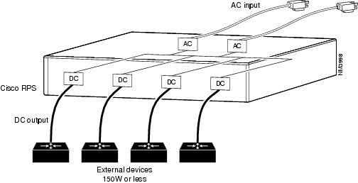
The Cisco RPS provides a quasi-redundant power source for four external devices that use up to 150W DC each. This configuration is allowed for all supported devices. You can use a one-to-one cable (one connector at each cable end) to connect four external devices to the four DC output power modules, as shown in Figure 1-1. The power source is quasi-redundant because there are two AC input power modules for the Cisco RPS and one DC output power module for each external device. The AC input to the Cisco RPS is fully redundant, but the DC output to the external devices is not.
Note
Figure 1-1 Quasi-Redundant Configuration
Fully Redundant Configuration
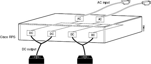
The Cisco RPS can provide a fully redundant power source for two of the supported routers or concentrators. You can use a two-to-one cable (ordered separately) to connect two external devices to the four DC output power modules, as shown in Figure 1-2. The two-to-one cable is a Y-shaped cable with two connectors at one end and one connector at the other end.
In this configuration, the connectors at one end of the Y-shaped cable connect to two Cisco RPS DC output power modules; the single connector on the other end of the cable connects to one external device. The power source is fully redundant, because there are two AC input modules and two DC output power modules connected to each external device. If any power module fails, there is a full backup.
Note
Figure 1-2 Fully Redundant Configuration
Redundant with Reboot
By using a mode of operation called redundant with reboot, you can connect more hubs and switches to the Cisco RPS and thereby extend its capacity or provide additional redundancy. Redundancy with reboot works for the following devices only: FastHub 400 series hubs, Catalyst 1900 series and Catalyst 2820 switches, and Catalyst 2900 series and Catalyst 3500 series XL switches. However, this configuration is not generally recommended, because a power supply failure will cause an interruption while the hub or switch reboots.
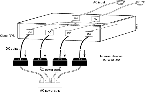
The redundant-with-reboot configuration is shown in Figure 1-3, where a straight-through one-to-one cable connects an external switch or hub to the Cisco RPS while the device is powered by its own internal power supply (the device AC power plug is connected).
Figure 1-3 Redundant-With-Reboot Configuration
In this configuration, one Cisco RPS can support four devices. The Cisco RPS and the external device internal power supply are both connected.
Note
After power up, a sense circuit in the Cisco RPS reads that the device has its AC power connected and shuts the Cisco RPS output off, preventing competition between the power supplies.
Normally, the external device internal power supply always provides power. If the internal power system of the hub or switch fails, the device powers down briefly (for approximately 30 seconds) until the Cisco RPS begins supplying power. When the device comes back up, the Cisco RPS is the main power source.
In this configuration, if the Cisco RPS fails or is disconnected, the external device does not power cycle, because its internal power supply has not been disturbed. When both the Cisco RPS and internal power supply are powered, the RPS LED on the external device blinks green, and the LED on the Cisco RPS front panel is off because the Cisco RPS is not supplying power.
Despite 30 seconds of downtime that occur when using redundancy with reboot, this configuration does provide additional redundancy and extends the capacity of the Cisco RPS.
Note
Quasi- and Fully Redundant Mixed Configuration
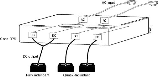
You can mix quasi-redundant and fully redundant configurations for supported devices. For example, two devices can be in quasi-redundant mode while one is in fully redundant mode (see Figure 1-4).
Figure 1-4 Mixed Configuration
Front and Rear Panel Descriptions
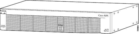
The LEDs on the Cisco RPS front panel show the Cisco RPS operational status. Figure 1-5 shows the front panel of the Cisco RPS.
Figure 1-5 Cisco RPS Front Panel
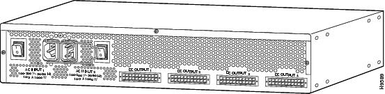
The Cisco RPS rear panel has two AC power connectors, each with an on/off switch, and four DC connectors for connecting to devices. Figure 1-6 shows the rear panel. See Chapter 3, "Connection Requirements," for information about required cables and connectors.
Figure 1-6 Cisco RPS Rear Panel
LEDs
The LEDs on the front panel of the Cisco RPS display the current operating condition of the Cisco RPS:
•
•
•
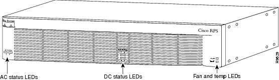
When the Cisco RPS is working properly, all LEDs on its front panel are solid green.
Note
Figure 1-7 shows the Cisco RPS front panel LEDs, and Table 1-2 explains the meaning of the colors.
Figure 1-7 Cisco RPS LEDs
Safety Recommendations
Follow these guidelines to guarantee general safety:
•
•
•
•
•
Safety Warnings
Safety warnings appear throughout this guide in procedures that, if performed incorrectly, might harm you. A warning symbol precedes each warning statement. (For information on safety warnings and translations, see the "Notes, Cautions, and Warnings" section on page xi.)
Safety with Electricity
Warning
Warning
Warning
Warning
Warning
Warning
Follow these guidelines when working on equipment powered by electricity:
•
•
•
–
–
–
–