Downloads |
 Feedback Feedback
|
Table Of Contents
Cisco 4G LTE Software Configuration Guide
Prerequisites for Configuring Cisco 4G LTE
Restrictions for Configuring Cisco 4G LTE
Example: Connecting to a Server Hosting a GPS Application
Short Message Service (SMS) Capabilities
IP Multimedia Subsystem Profiles
Verifying Modem Signal Strength and Service Availability
Creating, Modifying, or Deleting Modem Data Profiles
Usage Guidelines for Creating, Modifying, or Deleting Data Profiles
Configuring a SIM for Data Calls
Locking and Unlocking a SIM Card Using a PIN Code
Verifying the Security Information of a Modem
Configuring Automatic Authentication for a Locked SIM
Configuring an Encrypted PIN for a SIM
Applying a Modem Profile in a SIM Configuration
Configuring the Cellular Interface
Enabling 4G GPS and NMEA Data Streaming
Configuration Examples for 4G LTE
Example: Basic Cellular Interface Configuration: EHWIC-4G-LTE
Example: Basic Cellular Interface Configuration: Cisco 819 ISR
Cellular Interface Configuration for Always-On Connection
Dialer-Watch Configuration without External Dialer Interface
Dialer-Persistent Configuration with External Dialer Interface
Example: GRE Tunnel over Cellular Interface Configuration
4G-LTE Wireless WAN as Backup with NAT and IPSec
Unlocking the SIM Card: Example
Automatic SIM Authentication: Example
Changing the PIN Code: Example
Configuring an Encrypted PIN: Example
SMS Initiated Call Back Configuration: Example
Dialer-Watch Configuration without External Dialer Interface: Example
Dialer-Persistent Configuration with External Dialer Interface: Example
Upgrading the Modem Firmware Manually
MC7700 Manual Modem Firmware Upgrade: Example
MC7710 Manual Modem Firmware Upgrade: Example
MC7750 Manual Modem Firmware Upgrade: Example
Upgrading the Modem Firmware Using the EEM Scripts
Downloading the Modem Firmware and Installing the EEM Scripts
Running the EEM Scripts on the Router to Upgrade the Modem
Removing EEM Scripts from the Router once the Modem Upgrades Successfully
SNMP 4G LTE Configuration: Example
Verifying Service Availability
Modem Troubleshooting Using Integrated Modem DM Logging
Modem Settings for North America and Carriers Operating on 700 MHz Band
Electronic Serial Number (ESN)
Feature Information for Cisco 4G LTE
Cisco 4G LTE Software Configuration Guide
First Published: March 16, 2012Last Updated: December 17, 2013, OL-25146-06This document provides an overview of the software features and configuration information for Cisco Fourth-Generation (4G) Long-Term Evolution (LTE) Wireless WAN (WWAN) Enhanced High-Speed WAN Interface Cards ( EHWIC-4G-LTEs) and also Cisco 819HG-4G and Cisco 819G-4G LTE ISRs that support 4G LTE cellular and 3G cellular networks.
Cisco EHWIC-4G-LTEs are single-wide 4G Wireless WAN (WWAN) EHWICs supported on Cisco Integrated Services Router Generation 2 (ISR G2).For Cisco EHWIC-4G-LTE SKUs, faceplate, and LED descriptions, see the Cisco 4G LTE Hardware Installation Guide.
Finding Feature Information
Your software release may not support all the features documented in this module. For the latest feature information and caveats, see the release notes for your platform and software release. To find information about the features documented in this module and to see a list of the releases in which each feature is supported, see the "Feature Information for Cisco 4G LTE" section.
Use Cisco Feature Navigator to find information about platform support and Cisco software image support. To access Cisco Feature Navigator, go to http://www.cisco.com/go/cfn. An account on Cisco.com is not required.
Contents
•
Prerequisites for Configuring Cisco 4G LTE
•
•
•
•
Overview of Cisco 4G LTE
Cisco EHWIC-4G-LTEs are single-wide Wireless WAN (WWAN) EHWICs supported on Cisco 1900 Series, 2900 Series, and 3900 Series Integrated Services Router Generation 2 (ISR G2) routers. Cisco EHWIC-4G-LTEs operate over Fourth-Generation Long-Term Evolution (4G LTE) cellular networks and Third-Generation (3G) cellular networks. The Cisco 4G LTE WWAN EHWIC offers a highly secure, simplified, and cost-effective WAN alternative to DSL or Frame Relay. In areas where terrestrial broadband services (cable, DSL, or T1) are not available or are expensive, 4G LTE WWAN connectivity can be a viable alternative. Using the integrated services available on the Cisco ISR G2 routers, Cisco 4G LTE Wireless WAN EHWICs can provide instant and mobile communications during disasters and service outages.
Cisco 819 series ISR routers also support integrated 4G LTE wireless WAN.
The Cisco EHWIC-4G-LTEs and Cisco 819 series ISRs (Cisco 819HG-4G and Cisco 819G-4G LTE) supports the following modes:
•
•
•
Table 1 describes the Cisco 4G WWAN EHWIC product SKUs.
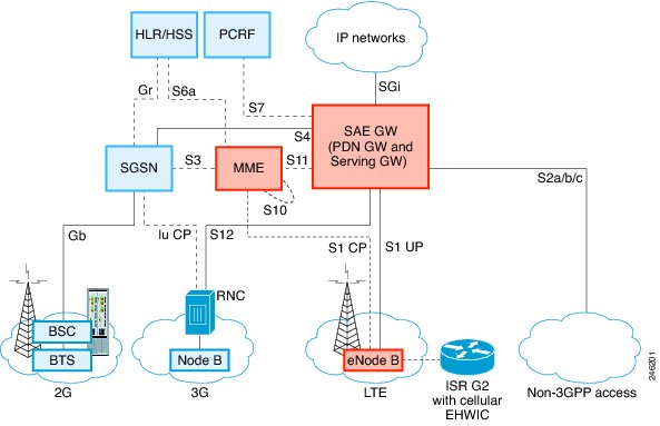
Figure 1 4G LTE Packet Core Network Architecture
Prerequisites for Configuring Cisco 4G LTE
•
•
•
•
•
Restrictions for Configuring Cisco 4G LTE
Follow these restrictions and usage guideline while configuring Cisco 4G LTE :
•
•
•
•
•
•
•
•
Cisco 4G LTE Features
Cisco 4G LTE WWAN EHWICs and Cisco 819HG-4G and Cisco 819G-4G LTE ISRs support the following major functionality:
•
•
•
•
•
•
•
•
•
•
•
•
•
•
4G GPS and NMEA
With the introduction of Cisco IOS Release 15.3(3)M, the Global Positioning System (GPS) feature is enabled by default on the supported Cisco 819 ISRs and Cisco 4G LTE EHWICs to provide the geographical location.
Active GPS is supported on the SubMiniature version A (SMA) port. Active GPS antenna is supported only in the standalone mode. An Active GPS antenna includes a built-in Low-Noise Amplifier that provides sufficient gain to overcome coaxial cable losses while providing the proper signal level to the GPS receiver. Active GPS antennae require power from the GPS receiver SMA port to operate. See the "Example: Connecting to a Server Hosting a GPS Application" section for more information.
National Marine Electronics Association (NMEA) streams GPS data either from a 4G EHWIC or a Cisco 819 ISR through a virtual COM port and a TCP/IP Ethernet connection to any marine device (such as a Windows-based PC) that runs a commercially available GPS-based application.
The following GPS and NMEA features are supported on the EHWIC-4G-LTE-V, EHWIC-4G-LTE-A, and EHWIC-4G-LTE-G4G SKUs and the Cisco 819HG-4G and Cisco 819G-4G LTE ISRs:
•
•
•
•
•
•
•
Note
For instructions on setting up the GPS antenna, see the Cisco 4G Indoor/Outdoor Active GPS Antenna (GPS-ACT-ANTM-SMA) document.
Example: Connecting to a Server Hosting a GPS Application
You can feed the NMEA data to a remote server that hosts the GPS application. The server can be connected to the router either directly using an Ethernet cable or through a LAN or WAN network. If the application supports serial port, run a serial port emulation program to create a virtual serial port over the LAN or WAN connection.
Note
To connect a Cisco 819 ISR through IP to a PC running Microsoft Streets & Trips, perform the following steps:
Step 1
Step 2
Step 3
Step 4
Step 5
Step 6
Step 7
Step 8
Step 9
Note
Short Message Service (SMS) Capabilities
The 4G EHWIC MC77xx modems support receiving, transmitting, archiving, and deleting of SMS messages. This support includes the ability to view up to 25 received texts, and archive more messages in a custom file location. SMS is supported on multiple carriers. MC77xx modems also have the capability to revert from LTE SMS to 3G and 2G SMS technology if necessary.
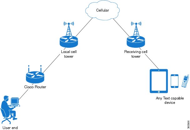
A sending device behind an MC77xx modem and router transmits an SMS text message over the 4G cellular link through cellular towers until it the message reaches the recipient's router, which then notifies the recipient device, such as a cell phone. The receiving device uses the same process to return a reply to the sending device. Figure 2 describes the flow from a mobile device to a sending device. For SMS transmission to work, end users must have a text-capable device, and optionally, a text plan. If end users do not have a text plan, standard SMS rates apply to their text transmissions.
The SMS-initiated Data Callback feature allows customers to set up a data connection by sending a text message to the 4G EHWIC MC77xx modem and includes the message screening functionality using the originating number to improve feature security and eliminate unauthorized callback requests.
Figure 2 SMS Network
Using a SIM Card
The 4G LTE EHWIC needs an active SIM card provided by a service provider. The SIM cards are usually provided in an unlocked state so that it can be used without a Personal Identification Number (PIN). If the SIM is unlocked, it can be inserted into an EHWIC and used without an authorization code.
The SIM can be initially locked with a PIN code (4 to 8 digits s long) defined by the service provider. Contact your service provider for the PIN code.
The SIM-Lock feature allows a SIM to be locked or unlocked with a PIN code so that it is used only in an authorized device. Perform the SIM lock and unlock procedures using the Cisco IOS CLI through a console or Telnet/SSH to the ISR.
After the SIM is locked, it cannot initiate a call unless authentication is done using the same PIN. Authentication is done automatically by Cisco IOS through configuration of the PIN. This mandatory configuration for automatic SIM authentication is done using the Cisco IOS CLI as part of the router startup configuration.
After the Cisco IOS configuration is in place, the ISR can initiate an LTE connection. The ISR uses the configured PIN to authenticate prior to the LTE connection. If the Cisco IOS PIN configuration is missing or if the PIN is incorrect, the SIM authentication will fail and the connection will not be initiated.
If the locked SIM is moved to a different ISR or to another device, or if the EHWIC in which the locked SIM resides is moved to a different EHWIC slot in the same ISR, the ISR configuration should be changed. The configuration is associated with the cellular controller that is specific to an ISR EHWIC slot number. This will ensure that the SIM card will not be used in any unauthorized device, or, if there are multiple LTE EHWICs in a single ISR, that the appropriate PIN is applied to each LTE EHWIC/SIM. An authentication command (with the same PIN used to lock the SIM) must be defined on the new device or on the new cellular controller slot to successfully initiate the LTE connection.
The following procedures are used to configure a SIM:
•
•
Caution
You can unblock a blocked SIM card using the PUK code. Contact your service provider for the PUK code.
Use the cellular <slot> lte sim unblock <PUK code> <new PIN code> command to unblock the SIM.
Data Account Provisioning
One or more modem data profiles can be created to provision a modem on a 3G or 4G EHWIC. An active wireless account with a service provider with one or more (dual) SIM cards must be installed. The modem data profile is preconfigured on the modem.
The following tasks are used to verify the signal strength and service availability of the modem and to create, modify, and delete modem data profiles:
•
•
IP Multimedia Subsystem Profiles
IP Multimedia Subsystem (IMS) profiles establish a session, and are a part of the modem configuration and are stored in the modem's NVRAM. An IMS network is an access-independent and standard-based IP connectivity service that enables different types of multimedia services to end users using common Internet-based protocols. See "Creating, Modifying, or Deleting Modem Data Profiles" section, for more information.
4G LTE LEDs
Table 2 describes 4G LTE EHWIC and 819 ISR LED behavior:
How to Configure Cisco 4G LTE
Note
•
•
•
•
Verifying Modem Signal Strength and Service Availability
Note
SUMMARY STEPS
1.
2.
3.
4.
5.
DETAILED STEPS
Creating, Modifying, or Deleting Modem Data Profiles
You can create multiple profiles on Cisco 819 ISRs and EHWICs. The following are the default internet profile numbers for some of the modem SKUs:
•
•
•
Usage Guidelines for Creating, Modifying, or Deleting Data Profiles
Follow these guidelines while you configure a data profile:
•
•
•
•
•
•
Note
Note
SUMMARY STEPS
1.
DETAILED STEPS
Configuration Examples
The following example shows how to change a default profile on EHWIC-4G-LTE-A:
router(config-controller)#lte sim profile 2router(config-controller)#endrouter#router#sh runBuilding configuration...controller Cellular 0/1lte sim profile 2router#ping 8.8.4.4 rep 10Type escape sequence to abort.Sending 10, 100-byte ICMP Echos to 8.8.4.4, timeout is 2 seconds:!!!!!!!!!!Success rate is 100 percent (10/10), round-trip min/avg/max = 284/364/600 msrouter#The following example shows the output of the show cellular command:
router#show cellular 0/1/0 profileProfile 1 = INACTIVE **--------PDP Type = IPv4Access Point Name (APN) = BroadbandProfile 2 = ACTIVE*--------PDP Type = IPv4PDP address = 10.176.207.8Access Point Name (APN) = BroadbandPrimary DNS address = 172.26.38.1Secondary DNS address = 172.26.38.2* - Default profile** - LTE attach profileThe following example shows the output of the show cellular command before you enable the debug command:
router#show cellular 0/0/0 profileProfile 1 = INACTIVE **--------PDP Type = IPv6Access Point Name (APN) = vzwimsProfile 2 = INACTIVE--------PDP Type = IPv4v6Access Point Name (APN) = vzwadminProfile 3 = ACTIVE*--------PDP Type = IPv4v6PDP address = 10.187.130.3Access Point Name (APN) = VZWINTERNETPrimary DNS address = 198.224.173.135Secondary DNS address = 198.224.174.135Profile 4 = INACTIVE--------PDP Type = IPv4v6Access Point Name (APN) = vzwapp* - Default profile /* Note** - LTE attach profile /* noteThe following example shows the output of the show cellular command after you enable the debug command:
router#debug cellular 0/0/0 messages profilePROFILE_3GPP2 debugging is onrouter#router #show cellular 0/0/0 profileProfile 1 = INACTIVE **--------PDP Type = IPv6Access Point Name (APN) = vzwimsProfile 2 = INACTIVE--------PDP Type = IPv4v6Access Point Name (APN) = vzwadminProfile 3 = ACTIVE*--------PDP Type = IPv4v6PDP address = 10.187.130.3Access Point Name (APN) = VZWINTERNETPrimary DNS address = 198.224.173.135Secondary DNS address = 198.224.174.135Profile 4 = INACTIVE--------PDP Type = IPv4v6Access Point Name (APN) = vzwapp3GPP2 Profiles:==============Profile 1 = INACTIVE--------PDN Type = IPv6Access Point Name (APN) = vzwimsProfile 2 = INACTIVE--------PDN Type = IPv4v6Access Point Name (APN) = vzwadminProfile 3 = INACTIVE*--------PDN Type = IPv4v6Access Point Name (APN) = VZWINTERNETProfile 4 = INACTIVE--------PDN Type = IPv4v6Access Point Name (APN) = vzwappProfile 5 = INACTIVE--------PDN Type = IPv4v6Access Point Name (APN) =Profile 6 = INACTIVE--------PDN Type = IPv4v6Access Point Name (APN) =* - Default profile** - LTE attach profileConfiguring a SIM for Data Calls
•
•
•
•
•
Locking and Unlocking a SIM Card Using a PIN Code
Perform this task to lock or unlock a SIM card given by your service provider.
Caution
Note
SUMMARY STEPS1.
DETAILED STEPS
Changing the PIN Code
Perform this task to change the PIN code of a SIM.
Note
SUMMARY STEPS1.
DETAILED STEPS
Verifying the Security Information of a Modem
Perform this task to verify the security information of a modem.
Note
SUMMARY STEPS1.
DETAILED STEPS
Step 1
show cellular unit security
Example:Device# show cellular 0/0/0 security
Shows the security information of the modem, including the SIM lock status.
Configuring Automatic Authentication for a Locked SIM
An unencrypted PIN can be configured to activate the Card Holder Verification (CHV1) code that authenticates a modem.
Caution
Note
Note
Note
SUMMARY STEPS
1.
2.
3.
or
lte sim authenticate 0 pin slot {0 | 1} (Cisco 819(H)G-4G-G ISR only)DETAILED STEPS
Step 1
configure terminal
Example:Device# configure terminal
Enters global configuration mode.
Step 2
controller cellular unit
Example:Device(config)# controller cellular 0/0
Enters the cellular controller configuration mode.
Step 3
For Cisco 819 ISRs and 4G EHWICs that do not have dual SIM feature:
lte sim authenticate 0 pin
For the Cisco 819(H)G-4G-G ISR that supports dual SIM feature:
lte sim authenticate 0 pin slot {0 | 1}
Example:Device(config-controller)# lte sim authenticate 0 1111
Authenticates the SIM CHV1 code by using an unencrypted (0) keyword and PIN. This PIN is sent to the modem for authentication with each subsequent LTE connection. If authentication passes based on the configured PIN, the data call is allowed. If authentication fails, the modem does not initiate the data call.
Note
Note
Configuring an Encrypted PIN for a SIM
To configure an encrypted PIN, the scrambled value of the PIN must be obtained. To get the scrambled Level 7 PIN and to configure the SIM CHV1 code for verification using this encrypted PIN, enter the following commands in the EXEC mode.
Note
Note
Note
SUMMARY STEPS
1.
2.
3.
4.
5.
6.
or
lte sim authenticate {0 | 7} pin slot {0 | 1} (Cisco 819(H)G-4G-G ISR only)7.
8.
9.
DETAILED STEPS
Step 1
configure terminal
Example:Device# configure terminal
Enters global configuration mode.
Step 2
service password-encryption
Example:Device(config)# service password-encryption
Enables password encryption.
Step 3
username name privilege 0 password pin
Example:Device(config)# username SIM privilege 0 password 1111
Creates username and password.
•
•
Step 4
do show run | i name
Example:Device(config)# do show run | i SIM
Shows the username configuration line with the encrypted level 7 PIN for the username created in Step 3 (user "SIM" in the example shown).
Copy the scrambled password for use in Step 6 (as the PIN).
Step 5
controller cellular unit
Example:Device(config)# controller cellular 0/0
Enters the cellular controller configuration mode.
Step 6
For the Cisco 4G LTE WWAN EHWICs and Cisco 819(H)G-4G LTE ISRs:
lte sim authenticate {0 | 7} pin
For the Cisco 819(H)G-4G-G ISR that supports dual SIM feature:
lte sim authenticate {0 | 7} pin slot {0 | 1}
Example:Device(config-controller)# lte sim authenticate 7 055A575E70
Authenticates the SIM CHV1 code by using the encrypted keyword 7 and the scrambled PIN from Step 4. The PIN is sent to the modem for authentication with each subsequent LTE connection. If authentication passes based on the configured PIN, the data call is allowed. If authentication fails, the modem does not initiate the data call.
Note
Step 7
exit
Example:Device(config-controller)# exit
(Optional) Exits the cellular controller configuration mode.
Step 8
no username name
Example:Device(config)# no username SIM
(Optional) Removes the username and password created in Step 3.
Step 9
no service password-encryption
Example:Device(config)# no service password-encryption
(Optional) Disables password encryption.
Applying a Modem Profile in a SIM Configuration
Note
SUMMARY STEPS
1.
2.
3.
or
lte sim profile number [ims number] slot {0 | 1} (Cisco 819(H)G-4G-G ISR only)DETAILED STEPS
Configuring a Dual SIM
The Dual SIM feature provides a failover mechanism in case the active SIM loses connectivity to the network. The Dual SIM feature is supported only on C819(H)G-4G-G-K9.
Note
Usage Guidelines for Configuring a Dual SIM
Follow these guidelines while you configure a dual SIM:
•
•
•
•
•
SUMMARY STEPS
1.
2.
3.
4.
5.
6.
7.
DETAILED STEPS
Note
Configuration Examples
The following example shows how to configure a dual SIM:
router# configure terminalrouter(config)# controller Cellular 0router(config-controller)# lte sim profile 1 ims 1 slot 0router(config-controller)# lte sim profile 2 ims 2 slot 1router(config-controller)# lte sim primary slot 1router(config-controller)# lte sim max-retry 20router(config-controller)# lte sim failovertimer 5The following example shows how to display an active profile on a SIM:
router#show cellular 0 profileProfile Information====================Profile 1 = INACTIVE--------PDP Type = IPv4Access Point Name (APN) = internet.telenor.seProfile 2 = ACTIVE* **--------PDP Type = IPv4PDP address = 78.78.16.214Access Point Name (APN) = telia.online.sePrimary DNS address = 195.67.199.18Secondary DNS address = 195.67.199.19* - Default profile** - LTE attach profileConfigured default profile for active SIM 1 is profile 2.The following example shows how to display the status of a dual SIM:
router#show cellular 0 securityActive SIM = 0SIM switchover attempts = 0Card Holder Verification (CHV1) = DisabledSIM Status = OKSIM User Operation Required = NoneNumber of CHV1 Retries remaining = 3router#The following example shows how to display the status of a dual SIM:
router#show controller cellular 0Interface Cellular04G WWAN Modem - Global Multimode LTE/DC-HSPA+/HSPA+/HSPA/UMTS/EDGE/GPRSCellular modem configuration======================================Modem is recognized as validmanufacture id: 0x00001199 product id: 0x000068A2Power status: ActiveSierra Wireless Direct IP MC7710 modem::Cellular Dual SIM details:---------------------------SIM 0 is presentSIM 1 is presentSIM 0 is active SIMData Call Setup
To set up a data call, use the following procedures:
•
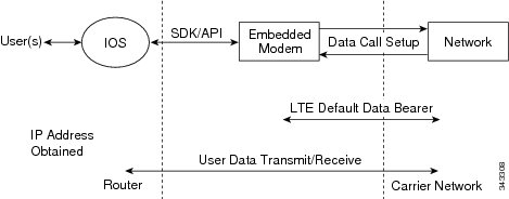
Figure 3 shows a typical data call setup.
Figure 3 Data Call Setup with EHWIC-4G-LTE
Configuring the Cellular Interface
To configure the cellular interface, enter the following commands starting in EXEC mode.
Note
Note
SUMMARY STEPS
1.
2.
3.
or
ip address ip-address mask
4.
5.
6.
7.
8.
9.
10.
11.
12.
13.
DETAILED STEPS
Note
Configuring DDR
To configure DDR for the cellular interface, enter the following commands starting in EXEC mode.
Note
SUMMARY STEPS
1.
2.
3.
or
ip address ip-address mask
4.
5.
6.
7.
8.
9.
10.
11.
12.
13.
14.
15.
16.
17.
18.
19.
20.
DETAILED STEPS
Configuring DDR Backup
To monitor the primary connection and initiate the backup connection when needed, the router can use one of the following methods:
•
•
•
Configuring Interfaces to Use a Backup Interface
Note
To configure one or more interfaces to use a backup interface, use the following commands, beginning in global configuration mode.
SUMMARY STEPS
1.
2.
3.
DETAILED STEPS
Enabling 4G GPS and NMEA Data Streaming
GPS NMEA data streaming to external NMEA 2.0-compliant GPS plotter applications can be enabled on 4G EHWIC modems and Cisco 819HG-4G and Cisco 819(H)G-4G LTE ISRs.
Note
SUMMARY STEPS
1.
2.
3.
4.
5.
or
lte gps nmea (4G EHWIC)6.
7.
8.
9.
10.
11.
DETAILED STEPS
Configuring 4G SMS Messaging
Note
SUMMARY STEPS
1.
2.
3.
4.
5.
6.
7.
8.
DETAILED STEPS
Configuration Examples for 4G LTE
•
•
•
•
•
•
•
•
Example: Basic Cellular Interface Configuration: EHWIC-4G-LTE
The following example shows how to configure the cellular interface to be used as a primary and is configured as the default route:
Device# show running-configchat-script lte "" "AT!CALL" TIMEOUT 20 "OK"interface Cellular0/0/0ip address negotiatedencapsulation slipdialer in-banddialer string ltedialer-group 1async mode interactiveip route 172.22.1.10 255.255.255.255 cellular 0/0/0dialer-list 1 protocol ip permitline 0/0/0script dialer ltemodem InOutExample: Basic Cellular Interface Configuration: Cisco 819 ISR
The following example shows how to configure the cellular interface to be used as primary and is configured as the default route:
chat-script lte "" "AT!CALL1" TIMEOUT 20 "OK"!!controller Cellular 0!!interface Cellular0ip address negotiatedencapsulation slipload-interval 30dialer in-banddialer idle-timeout 0dialer string ltedialer-group 1no peer default ip addressasync mode interactiverouting dynamic!ip route 172.22.1.10 255.255.255.255 cellular 0/0/0!dialer-list 1 protocol ip permit!line 3script dialer ltemodem InOutno exectransport input alltransport output all!Cellular Interface Configuration for Always-On Connection
This section provides the following configuration examples:
•
•
Dialer-Watch Configuration without External Dialer Interface
The following example shows how to configure dialer-watch without external dialer interface. The bold text is used to indicate important commands that are specific to dialer-watch.
chat-script lte "" "AT!CALL" TIMEOUT 20 "OK"interface Cellular0/0/0ip address negotiatedencapsulation slipdialer in-banddialer string LTEdialer watch-group 1async mode interactive!dialer watch-list 1 ip 5.6.7.8 0.0.0.0dialer watch-list 1 delay route-check initial 60dialer watch-list 1 delay connect 1!ip route 0.0.0.0 0.0.0.0 cellular 0/0/0line 0/0/0script dialer LTEmodem InOutno exectransport input alltransport output allDialer-Persistent Configuration with External Dialer Interface
The following example shows how to configure dialer-persistent with external dialer interface. The bold text is used to indicate important commands that are specific to dialer-persistent.
chat-script lte "" "AT!CALL" TIMEOUT 20 "OK"interface Cellular0/0/0ip address negotiatedencapsulation slipdialer in-banddialer pool-member 1async mode interactiverouting dynamicinterface Dialer1ip address negotiatedencapsulation slipdialer pool 1dialer idle-timeout 0dialer string ltedialer persistentdialer-group 1!dialer-list 1 protocol ip permitip route 0.0.0.0 0.0.0.0 dialer 1line 0/0/0script dialer ltemodem InOutno exectransport input alltransport output allExample: GRE Tunnel over Cellular Interface Configuration
The following example shows how to configure the static IP address when a GRE tunnel interface is configured with ip address unnumbered cellular interface:
Note
Note
interface Tunnel2ip unnumbered <internal LAN interface GE0/0 etc.>tunnel source Cellular0tunnel destination a.b.c.dinterface Cellular0ip address negotiatedencapsulation slipno ip mroute-cachedialer in-banddialer string ltedialer-group 1async mode interactive4G-LTE Wireless WAN as Backup with NAT and IPSec
The following example shows how to configure the 4G-LTE wireless WAN on the router as backup with NAT and IPSec:
Note
ip dhcp excluded-address 10.4.0.254!ip dhcp pool lan-poolnetwork 10.4.0.0 255.255.0.0dns-server 10.4.0.254default-router 10.4.0.254!!chat-script lte "" "AT!CALL" TIMEOUT 20 "OK"crypto isakmp policy 1encr 3desauthentication pre-sharecrypto isakmp key address a.b.c.d!!crypto ipsec transform-set ah-sha-hmac esp-3des!crypto map gsm1 10 ipsec-isakmpset peer a.b.c.dset transform-setmatch address 103!!interface ATM0/0/0no ip addressip virtual-reassemblyload-interval 30no atm ilmi-keepalivedsl operating-mode auto!interface ATM0/0/0.1 point-to-pointbackup interface Cellular0/3/0ip nat outsideip virtual-reassemblyno snmp trap link-statuspvc 0/35pppoe-client dial-pool-number 2!!interface Cellular0/3/0ip address negotiatedip nat outsideip virtual-reassemblyencapsulation slipno ip mroute-cachedialer in-banddialer idle-timeout 0dialer string ltedialer-group 1async mode interactivecrypto map gsm1!interface Vlan104description used as default gateway address for DHCP clientsip address 10.4.0.254 255.255.0.0ip nat insideip virtual-reassembly!interface Dialer2ip address negotiatedip mtu 1492ip nat outsideip virtual-reassemblyencapsulation pppload-interval 30dialer pool 2dialer-group 2ppp authentication chap callinppp chap hostname cisco@dsl.comppp chap password 0 ciscoppp ipcp dns requestcrypto map gsm1!ip local policy route-map track-primary-ifip route 0.0.0.0 0.0.0.0 Dialer2 track 234ip route 0.0.0.0 0.0.0.0 Cellular0/3/0 254!!ip nat inside source route-map nat2cell interface Cellular0/3/0 overloadip nat inside source route-map nat2dsl interface Dialer2 overload!ip sla 1icmp-echo 2.2.2.2 source-interface Dialer2timeout 1000frequency 2ip sla schedule 1 life forever start-time nowaccess-list 1 permit anyaccess-list 101 deny ip 10.4.0.0 0.0.255.255 10.0.0.0 0.255.255.255access-list 101 permit ip 10.4.0.0 0.0.255.255 anyaccess-list 102 permit icmp any host 2.2.2.2access-list 103 permit ip 10.4.0.0 0.0.255.255 10.0.0.0 0.255.255.255dialer-list 1 protocol ip list 1dialer-list 2 protocol ip permit!!route-map track-primary-if permit 10match ip address 102set interface Dialer2!route-map nat2dsl permit 10match ip address 101match interface Dialer2!route-map nat2cell permit 10match ip address 101match interface Cellular0/3/0!line 0/3/0exec-timeout 0 0script dialer lteloginmodem InOut
Note
SIM Configuration: Examples
•
•
•
•
•
Locking the SIM Card: Example
The following example shows how to lock the SIM. The italicized text in this configuration example is used to indicate comments and are not be seen when a normal console output is viewed.
Device# sh cellular 0/0/0 securityCard Holder Verification (CHV1) = DisabledSIM Status = OKSIM User Operation Required = NoneNumber of CHV1 Retries remaining = 3Device#!! SIM is in unlocked state.!Device# cellular 0/0/0 lte sim lock 1111!!!WARNING: SIM will be locked with pin=1111(4).Do not enter new PIN to lock SIM. Enter PIN that the SIM is configured with.Call will be disconnected!!!Are you sure you want to proceed?[confirm]Device#Apr 26 19:35:28.339: %CELLWAN-2-MODEM_DOWN: Modem in HWIC slot 0/0 is DOWNApr 26 19:35:59.967: %CELLWAN-2-MODEM_UP: Modem in HWIC slot 0/0 is now UPDevice#Device# sh cellular 0/0/0 securityCard Holder Verification (CHV1) = EnabledSIM Status = LockedSIM User Operation Required = Enter CHV1Number of CHV1 Retries remaining = 3Device#!! SIM is in locked state.!Unlocking the SIM Card: Example
The following example shows how to unlock the SIM. The italicized text throughout this configuration example is used to indicate comments and will not be seen when a normal console output is viewed.
Device# sh cellular 0/0/0 securityCard Holder Verification (CHV1) = EnabledSIM Status = LockedSIM User Operation Required = Enter CHV1Number of CHV1 Retries remaining = 3Device#!! SIM is in locked state.!Device# cellular 0/0/0 lte sim unlock 1111!!!WARNING: SIM will be unlocked with pin=1111(4).Do not enter new PIN to unlock SIM. Enter PIN that the SIM is configured with.Call will be disconnected!!!Are you sure you want to proceed?[confirm]Device#Device# sh cellular 0/0/0 securityCard Holder Verification (CHV1) = DisabledSIM Status = OKSIM User Operation Required = NoneNumber of CHV1 Retries remaining = 3Device#!! SIM is in unlocked state.!Automatic SIM Authentication: Example
The following example shows how to configure automatic SIM authentication. The italicized text throughout this configuration example is used to indicate comments and will not be seen when a normal console output is viewed.
Device# show cellular 0/0/0 securityCard Holder Verification (CHV1) = DisabledSIM Status = OKSIM User Operation Required = NoneNumber of CHV1 Retries remaining = 3Device#!! SIM is in unlocked state.!Device# cellular 0/0/0 lte sim lock 1111!!!WARNING: SIM will be locked with pin=1111(4).Do not enter new PIN to lock SIM. Enter PIN that the SIM is configured with.Call will be disconnected!!!Are you sure you want to proceed?[confirm]Device#Apr 26 21:22:34.555: %CELLWAN-2-MODEM_DOWN: Modem in HWIC slot 0/0 is DOWNApr 26 21:23:06.495: %CELLWAN-2-MODEM_UP: Modem in HWIC slot 0/0 is now UPDevice#Device# sh cellular 0/0/0 securityCard Holder Verification (CHV1) = EnabledSIM Status = LockedSIM User Operation Required = Enter CHV1Number of CHV1 Retries remaining = 3Device#!! SIM is in locked state. SIM needs to be in locked state for SIM authentication to! work.!Device#Device# conf termEnter configuration commands, one per line. End with CNTL/Z.Device(config)# controller cellular 0/0Device(config-controller)# lte sim authenticate 0 1111CHV1 configured and sent to modem for verificationDevice(config-controller)# endDevice#Apr 26 21:23:50.571: %SYS-5-CONFIG_I: Configured from console by consoleDevice#Device# sh cellular 0/0/0 securityCard Holder Verification (CHV1) = EnabledSIM Status = OKSIM User Operation Required = NoneNumber of CHV1 Retries remaining = 3Device#!! SIM is now in locked state but it can be used for connectivity since authentication is! good. Authentication can be saved in the router configuration so that when you boot up! the router with the same locked SIM, connection can be established with the correct! Cisco IOS configuration.!Changing the PIN Code: Example
The following example shows how to change the assigned PIN code. The italicized text throughout this configuration example is used to indicate comments and will not be seen when a normal console output is viewed.
Device# sh cellular 0/0/0 securityCard Holder Verification (CHV1) = DisabledSIM Status = OKSIM User Operation Required = NoneNumber of CHV1 Retries remaining = 3Device#!! SIM is in unlocked state.!Device#Device# cellular 0/0/0 lte sim lock 1111!!!WARNING: SIM will be locked with pin=1111(4).Do not enter new PIN to lock SIM. Enter PIN that the SIM is configured with.Call will be disconnected!!!Are you sure you want to proceed?[confirm]Device#Apr 26 21:58:11.903: %CELLWAN-2-MODEM_DOWN: Modem in HWIC slot 0/0 is DOWNApr 26 21:58:43.775: %CELLWAN-2-MODEM_UP: Modem in HWIC slot 0/0 is now UPDevice#Device# sh cellular 0/0/0 securityCard Holder Verification (CHV1) = EnabledSIM Status = LockedSIM User Operation Required = Enter CHV1Number of CHV1 Retries remaining = 3Device#!! SIM is in locked state. SIM needs to be in locked state to change its PIN.!Device#Device# cellular 0/0/0 lte sim change-pin 1111 0000!!!WARNING: SIM PIN will be changed from:1111(4) to:0000(4)Call will be disconnected. If old PIN is entered incorrectly in 3 attempt(s), SIM will be blocked!!!Are you sure you want to proceed?[confirm]Resetting modem, please wait...CHV1 code change has been completed. Please enter the new PIN in controller configuration for verficationDevice#Apr 26 21:59:16.735: %CELLWAN-2-MODEM_DOWN: Modem in HWIC slot 0/0 is DOWNApr 26 21:59:48.387: %CELLWAN-2-MODEM_UP: Modem in HWIC slot 0/0 is now UPDevice#Device#Device# sh cellular 0/0/0 securityCard Holder Verification (CHV1) = EnabledSIM Status = LockedSIM User Operation Required = Enter CHV1Number of CHV1 Retries remaining = 3Device#!! SIM stays in locked state, as expected, but with new PIN.!Device# cellular 0/0/0 lte sim unlock 0000!!!WARNING: SIM will be unlocked with pin=0000(4).Do not enter new PIN to unlock SIM. Enter PIN that the SIM is configured with.Call will be disconnected!!!Are you sure you want to proceed?[confirm]Device#Device# show cellular 0/0/0 securityCard Holder Verification (CHV1) = DisabledSIM Status = OKSIM User Operation Required = NoneNumber of CHV1 Retries remaining = 3Device#!! Unlock with new PIN is successful. Hence, changing PIN was successful.!Configuring an Encrypted PIN: Example
The following example shows how to configure automatic SIM authentication using an encrypted PIN. The italicized text throughout this configuration example is used to indicate comments and will not be seen when a normal console output is viewed.
Device# configure terminalEnter configuration commands, one per line. End with CNTL/Z.Device(config)# service password-encryptionDevice(config)# username SIM privilege 0 password 1111Device(config)# do sh run | i SIMusername SIM privilege 0 password 7 055A575E70.!! Copy the encrypted level 7 PIN. Use this scrambled PIN in the SIM authentication! command.!Device(config)#Device(config)# controller cellular 0/0Device(config-controller)# lte sim authenticate 7 055A575E70CHV1 configured and sent to modem for verificationDevice(config-controller)# exitDevice(config)# no username SIMDevice(config)# endMay 14 20:20:52.603: %SYS-5-CONFIG_I: Configured from console by consoleSMS Initiated Call Back Configuration: Example
The following example shows how to configure SMS initiated data callback feature on a dialer interface to set up a data connection by sending a text message to the modem and securing the data connection by using the originating (caller's) number to eliminate unauthorized callback requests.
Note
chat-script lte "" "AT!CALL" TIMEOUT 20 "OK"interface Cellular0/0/0ip address negotiatedencapsulation slipdialer in-banddialer pool-member 1async mode interactiverouting dynamic!interface Dialer1ip address negotiatedencapsulation slipdialer pool 1dialer idle-timeout 0dialer string ltedialer caller 14001234567 callbackdialer-group 1!ip route 172.22.1.10 255.255.255.255 Cellular0/0/0dialer-list 1 protocol ip permit!line 0/0/0script dialer LTEmodem InOutno exectransport input alltransport output allDialer-Watch Configuration without External Dialer Interface: Example
The following example shows how to configure the dialer-watch without external dialer interface. The bold text is used to indicate important commands that are specific to the dialer-watch:
chat-script lte "" "AT!CALL1" TIMEOUT 20 "OK"interface Cellular0ip address negotiatedencapsulation slipdialer in-banddialer string LTEdialer watch-group 1async mode interactive!dialer watch-list 1 ip 5.6.7.8 0.0.0.0dialer watch-list 1 delay route-check initial 60dialer watch-list 1 delay connect 1!ip route 0.0.0.0 0.0.0.0 cellular 0line 3script dialer LTEmodem InOutno exectransport input alltransport output allDialer-Persistent Configuration with External Dialer Interface: Example
The following example shows how to configure the dialer-persistent with external dialer interface. The bold text is used to indicate important commands that are specific to the dialer-persistent:
interface Cellular0ip address negotiatedencapsulation slipdialer in-banddialer pool-member 1async mode interactiverouting dynamicinterface Dialer1ip address negotiatedencapsulation slipdialer pool 1dialer idle-timeout 0dialer string ltedialer persistentdialer-group 1!dialer-list 1 protocol ip permitip route 0.0.0.0 0.0.0.0 dialer 1line 3script dialer ltemodem InOutno exectransport input alltransport output allUpgrading the Modem Firmware
The modems described in Table 3 from Sierra Wireless can use the Cisco 4G-LTE EHWICs and Cisco WWAN 4G ISR model G2. The firmware for the modem is upgradable using Cisco IOS commands. The firmware is a Crossword Express file (cwe) and can be downloaded from the wireless software download page on Cisco.com.
Caution
Caution
Note
Note
Upgrading the Modem Firmware Manually
Cisco recommends the manual upgrade process for the LTE modem firmware and IOS software image for all new deployments and the following existing deployments:
•
•
•
Note
SUMMARY STEPS
Step 1
http://software.cisco.com/download/navigator.html
Note
Step 2
Products -> Cisco Interfaces and Modules -> Cisco High-Speed WAN Interface CardsStep 3
Figure 4 Cisco Download Software Web Page
Step 4
Step 5
Note
Step 6
Step 7
DETAILED STEPS
Step 1
Go to the Cisco Wireless WAN software download website at:
Provides access to Cisco Wireless WAN software downloads. Select firmware for Cisco 4G.
Note
Step 2
On this page, select from the following options:
Products -> Cisco Interfaces and Modules -> Cisco High-Speed WAN Interface CardsAfter the Cisco High-Speed WAN interface Cards is selected, a list of available cards displays in the third column as shown in Figure 4. Select your product in the third column and download the appropriate LTE firmware.
Step 3
Download the selected LTE firmware release.
Download the modem firmware file to flash memory on the router.
Step 4
terminal monitor
Example:Device# terminal monitor
Enables the logging console in privileged EXEC mode.
Step 5
Device# microcode reload cellular 0 1 modem-provision flash:<filename>.cwe
F/W Upgrade: Complete Successfully
Initiates the firmware upgrade process.
•
•
Note
Step 6
For the LTE 4G EHWIC:
show cellular unit
For the 819 with embedded AT&T LTE:
show cellular 0 hardware
Example:Device# show cellular 0 hardware
Modem Firmware Version = SWI9200X_03.05.10.02
Modem Firmware built = 2012/02/25 11:58:38
Verifies the firmware upgrade process.
Step 7
reload
Reloads the IOS application software image to complete the firmware upgrade.
Note
MC7700 Manual Modem Firmware Upgrade: Example
Device#microcode reload cellular 0 0 modem-provision flash:MC7700_ATT_03.05.10.02_00.cweReload microcode? [confirm] <hit enter key>Log status of firmware download in router flash?[confirm] <hit enter key>Firmware download status will be logged in flash:fwlogfileMicrocode Reload Process launched for Cellular 37946756; hw type = 0x6F3Device#*****************************************************The interface will be Shut Down for Firmware UpgradeThis will terminate any active data connections.*****************************************************Modem radio has been turned off*****************************************************Modem will be upgraded!Upgrade process will take up to 15 minutes. Duringthis time the modem will be unusable.Please do not remove power or reload the router duringthe upgrade process.*****************************************************Sending F/W[MC7700_ATT_03.05.10.02_00.cwe] to the card [41569157 bytes]:Firmware file: MC7700_ATT_03.05.10.02_00.cwe sent to the cardThe current modem F/W App Version: SWI9200X_01.00.03.01AP R2492 CARMD-EN-10526 2011/07/01 19:31:09The current modem F/W Boot Version: SWI9200X_01.00.03.01BT R2492 CARMD-EN-10526 2011/07/01 19:28:52The current modem Carrier String: 5The current modem Device ID: MC7700The current modem Package Identifier: MC7700_01.00.03.01_00_vzw_020.006_001The current modem SKU ID: 1584083FW UPgrade: In the progress.*Feb 21 23:39:35.407: %CISCO800-2-MODEM_DOWN: Cellular0 modem is now DOWN.F/W Upgrade: Complete Successfully*Feb 21 23:42:00.475: %CISCO800-2-MODEM_UP: Cellular0 modem is now UP.*Feb 21 23:42:00.475: %CISCO800-2-MODEM_DOWN: Cellular0 modem is now DOWN.*Feb 21 23:42:05.475: %CISCO800-2-MODEM_UP: Cellular0 modem is now UP.Modem radio has been turned onDevice#show cellular 0 hardware | incl Modem Firmware VersionModem Firmware Version = SWI9200X_03.05.10.02MC7710 Manual Modem Firmware Upgrade: Example
Device#microcode reload cellular 0 0 modem-provision
flash:MC7710_Global_03.05.19.04_00.cwe
Reload microcode? [confirm] <hit enter key>Log status of firmware download in router flash?[confirm] <hit enter key>Firmware download status will be logged in flash:fwlogfileMicrocode Reload Process launched for Cellular 37946756; hw type = 0x6F3Device#*****************************************************The interface will be Shut Down for Firmware UpgradeThis will terminate any active data connections.*****************************************************Modem radio has been turned off*****************************************************Modem will be upgraded!Upgrade process will take up to 15 minutes. Duringthis time the modem will be unusable.Please do not remove power or reload the router duringthe upgrade process.*****************************************************Sending F/W[MC7710_Global_03.05.19.04_00.cwe] to the card [41569157 bytes]:Firmware file: MC7710_Global_03.05.19.04_00.cwe sent to the cardThe current modem F/W App Version: SWI9200X_03.00.11.00AP R2492 CARMD-EN-10526 2011/07/01 19:31:09The current modem F/W Boot Version: SWI9200X_03.00.11.00BT R2492 CARMD-EN-10526 2011/07/01 19:28:52The current modem Carrier String: 5The current modem Device ID: MC7710The current modem Package Identifier: MC7710_03.00.11.00_00_vzw_020.006_001The current modem SKU ID: 1584083FW UPgrade: In the progress.*Feb 21 23:39:35.407: %CISCO800-2-MODEM_DOWN: Cellular0 modem is now DOWN.F/W Upgrade: Complete Successfully*Feb 21 23:42:00.475: %CISCO800-2-MODEM_UP: Cellular0 modem is now UP.*Feb 21 23:42:00.475: %CISCO800-2-MODEM_DOWN: Cellular0 modem is now DOWN.*Feb 21 23:42:05.475: %CISCO800-2-MODEM_UP: Cellular0 modem is now UP.Modem radio has been turned onDevice#show cellular 0 hardware | incl Modem Firmware VersionModem Firmware Version = SWI9200X_03.05.19.04MC7750 Manual Modem Firmware Upgrade: Example
Device#microcode reload cellular 0 0 modem-provision flash:MC7750_VZW_03.05.10.06_00.cweReload microcode? [confirm] <hit enter key>Log status of firmware download in router flash?[confirm] <hit enter key>Firmware download status will be logged in flash:fwlogfileMicrocode Reload Process launched for Cellular 37946756; hw type = 0x6F3Device#*****************************************************The interface will be Shut Down for Firmware UpgradeThis will terminate any active data connections.*****************************************************Modem radio has been turned off*****************************************************Modem will be upgraded!Upgrade process will take up to 15 minutes. Duringthis time the modem will be unusable.Please do not remove power or reload the router duringthe upgrade process.*****************************************************Sending F/W[MC7750_VZW_03.05.10.06_00.cwe] to the card [41569157 bytes]:Firmware file: MC7750_VZW_03.05.10.06_00.cwe sent to the cardThe current modem F/W App Version: SWI9600M_01.00.09.03AP R2492 CARMD-EN-10526 2011/07/01 19:31:09The current modem F/W Boot Version: SWI9600M_01.00.09.03BT R2492 CARMD-EN-10526 2011/07/01 19:28:52The current modem Carrier String: 5The current modem Device ID: MC7750The current modem Package Identifier: MC7750_01.00.09.03_00_vzw_020.006_001The current modem SKU ID: 1584083FW UPgrade: In the progress.*Feb 21 23:39:35.407: %CISCO800-2-MODEM_DOWN: Cellular0 modem is now DOWN.F/W Upgrade: Complete Successfully*Feb 21 23:42:00.475: %CISCO800-2-MODEM_UP: Cellular0 modem is now UP.*Feb 21 23:42:00.475: %CISCO800-2-MODEM_DOWN: Cellular0 modem is now DOWN.*Feb 21 23:42:05.475: %CISCO800-2-MODEM_UP: Cellular0 modem is now UP.Modem radio has been turned onDevice#show cellular 0 hardware | incl Modem Firmware VersionModem Firmware Version = SWI9600M_03.05.10.06Upgrading the Modem Firmware Using the EEM Scripts
For existing field deployments where LTE is the only WAN interface, and there is no local or out-of-band administrative access to the ISR, an automated upgrade method using a Cisco IOS Embedded Event Manager (EEM) script is recommended. The EEM script upgrades the modem firmware and reloads the ISR with the IOS software image that is compatible with the new firmware release.
Downloading the Modem Firmware and Installing the EEM Scripts
SUMMARY STEPS
Step 1
http://software.cisco.com/download/navigator.html
Note
Step 2
Products -> Cisco Interfaces and Modules -> Cisco High-Speed WAN Interface CardsStep 3
Step 4
Step 5
Step 6
Step 7
Step 8
Step 9
DETAILED STEPS
Step 1
Go to the Cisco Wireless WAN software download website at:
Provides access to Cisco Wireless WAN software downloads. Select firmware for Cisco 4G.
Note
Step 2
On this page, select from the following options:
Products -> Cisco Interfaces and Modules -> Cisco High-Speed WAN Interface CardsAfter the Cisco High-Speed WAN interface Cards is selected, a list of available cards displays in the third column as shown in Figure 4. Select your product in the third column and download the appropriate LTE firmware.
Step 3
Download the selected LTE firmware release.
Download the modem firmware file to flash memory on the router.
Step 4
no boot system flash:filename
Example:Device(config)# no boot system flash:cxxx-universalk9-mz.SPA.152-4.M2
Deletes any boot system flash: commands from the running configuration in global configuration mode.
Step 5
terminal monitor
Example:Device# terminal monitor
Enables the logging console in privileged EXEC mode.
Step 6
configure terminal
Example:Device# configure terminal
Enters global configuration mode.
Step 7
Copy EEM Script 1 and EEM Script 2 for your modem (see the following this section) and paste this text into the router's running configuration.
Installs the EEM scripts on the router.
Note
action 1.3.4 set old_IOS
"c$platform-universalk9-mz.SSA.V152_4_M_LT
E"
with:
action 1.3.4 set old_IOS
"c$platform-universalk9-mz.SPA.152-4.M2"
Step 8
show event manager policy registered
Example:Device# show event manager policy registered
Verifies that the policy is registered.
Note
EEM Script 1 for MC7700 Modem
event manager applet FW authorization bypassevent none maxrun 1200action 1.0 if $_none_argc ne "1"action 1.0.1 syslog msg "Incorrect number of arguments passed. Please check and try again"action 1.0.2 exitaction 1.0.3 endaction 1.1 cli command "enable"action 1.2 set slot_number "$_none_arg1"action 1.3 cli command "show version | incl System image file"action 1.3.1 regexp "(.*)c(.*)-universalk9-(.*)\"" "$_cli_result" _match _sub1 _sub2 _sub3action 1.3.2 set platform "$_sub2"action 1.3.3 set current_IOS "c$_sub2-universalk9-$_sub3"action 1.3.4 set old_IOS "c$platform-universalk9-mz.SPA.152-4.M2"action 1.3.5 set new_IOS "c$platform-universalk9-mz.SPA.152-4.M3"action 1.3.6 set firmware "MC7700_ATT_03.05.10.02_00.cwe"action 1.3.7 set old_firmware "SWI9200X_01.00.03.01"action 1.3.8 set new_firmware "SWI9200X_03.05.10.02"action 1.4 if $platform eq "800"action 1.4.1 set cellular_interface 0action 1.5 elseaction 1.5.1 set cellular_interface "0/$slot_number/0"action 1.5.2 endaction 1.6 cli command "show cellular $cellular_interface hardware | incl Modem Firmware Version"action 1.7 string first "$new_firmware" "$_cli_result"action 1.8 if $_string_result ge 0action 1.8.1 syslog msg "Modem is already on new firmware $new_firmware. Exiting upgrade!!"action 1.8.2 exitaction 1.8.3 endaction 2.1 if $current_IOS ne $old_IOSaction 2.1.1 syslog msg "Current IOS version is incorrect. Please run $old_IOS before starting upgrade. Exiting upgrade!!"action 2.1.2 exitaction 2.2 endaction 2.3 cli command "show flash: | incl $new_IOS"action 3.0 string first "$new_IOS" "$_cli_result"action 3.1 if $_string_result lt 0action 3.1.1 syslog msg "$new_IOS is not present in flash. Exiting upgrade!!"action 3.1.2 exitaction 3.2 endaction 3.3 cli command "show flash: | incl $firmware"action 5.0 string first "$firmware" "$_cli_result"action 5.1 if $_string_result lt 0action 5.1.1 syslog msg "$firmware is not present in flash. Exiting upgrade!!"action 5.1.2 exitaction 5.2 endaction 5.3 cli command "configure terminal"action 5.4 cli command "no boot system"action 5.5 cli command "end"action 6.1 cli command "microcode reload cellular 0 $slot_number modem-provision flash:$firmware" pattern "confirm"action 6.2 cli command "y"action 6.3 wait 400action 6.4 cli command "event manager run router_reload $old_IOS $new_IOS $old_firmware $cellular_interface"action 6.5 wait 120action 6.6 exitEEM Script 2 for MC7700 Modem
event manager applet router_reload authorization bypassevent none maxrun 120action 1.0 set old_IOS "$_none_arg1"action 1.1 set new_IOS "$_none_arg2"action 1.2 set old_firmware "$_none_arg3"action 1.3 set cellular_interface "$_none_arg4"action 1.4 cli command "enable"action 2.0 cli command "show cellular $cellular_interface hardware | inc Modem Firmware Version"action 2.1 set _string_result "0"action 2.2 string first "$old_firmware" "$_cli_result"action 2.3 if $_string_result ge "0"action 2.3.1 set boot_IOS "$old_IOS"action 2.3.2 syslog msg "Firmware did not Upgrade successfully. Please try again after reload"action 2.4 elseaction 2.4.1 set boot_IOS "$new_IOS"action 2.4.2 syslog msg "Firmware upgraded successfully. value= $_string_result"action 2.4.3 endaction 2.5 cli command "configure terminal"action 2.5.1 cli command "boot system flash:$boot_IOS"action 2.5.2 cli command "config-register 0x2102"action 2.5.3 cli command "interface cellular $cellular_interface"action 2.5.4 cli command "no shut"action 2.5.5 cli command "end"action 2.5.6 cli command "write memory"action 2.5.7 reloadEEM Script 1 for MC7710 Modem
event manager applet FW authorization bypassevent none maxrun 1200action 1.0 if $_none_argc ne "1"action 1.0.1 syslog msg "Incorrect number of arguments passed. Please check and try again"action 1.0.2 exitaction 1.0.3 endaction 1.1 cli command "enable"action 1.2 set slot_number "$_none_arg1"action 1.3 cli command "show version | incl System image file"action 1.3.1 regexp "(.*)c(.*)-universalk9-(.*)\"" "$_cli_result" _match _sub1 _sub2 _sub3action 1.3.2 set platform "$_sub2"action 1.3.3 set current_IOS "c$_sub2-universalk9-$_sub3"action 1.3.4 set old_IOS "c$platform-universalk9-mz.SPA.152-4.M2"action 1.3.5 set new_IOS "c$platform-universalk9-mz.SPA.152-4.M3"action 1.3.6 set firmware "MC7710_Global_03.05.19.04_00.cwe"action 1.3.7 set old_firmware "SWI9200X_03.00.11.00"action 1.3.8 set new_firmware "SWI9200X_03.05.19.04"action 1.4 if $platform eq "800"action 1.4.1 set cellular_interface 0action 1.5 elseaction 1.5.1 set cellular_interface "0/$slot_number/0"action 1.5.2 endaction 1.6 cli command "show cellular $cellular_interface hardware | incl Modem Firmware Version"action 1.7 string first "$new_firmware" "$_cli_result"action 1.8 if $_string_result ge 0action 1.8.1 syslog msg "Modem is already on new firmware $new_firmware. Exiting upgrade!!"action 1.8.2 exitaction 1.8.3 endaction 2.1 if $current_IOS ne $old_IOSaction 2.1.1 syslog msg "Current IOS version is incorrect. Please run $old_IOS before starting upgrade. Exiting upgrade!!"action 2.1.2 exitaction 2.2 endaction 2.3 cli command "show flash: | incl $new_IOS"action 3.0 string first "$new_IOS" "$_cli_result"action 3.1 if $_string_result lt 0action 3.1.1 syslog msg "$new_IOS is not present in flash. Exiting upgrade!!"action 3.1.2 exitaction 3.2 endaction 3.3 cli command "show flash: | incl $firmware"action 5.0 string first "$firmware" "$_cli_result"action 5.1 if $_string_result lt 0action 5.1.1 syslog msg "$firmware is not present in flash. Exiting upgrade!!"action 5.1.2 exitaction 5.2 endaction 5.3 cli command "configure terminal"action 5.4 cli command "no boot system"action 5.5 cli command "end"action 6.1 cli command "microcode reload cellular 0 $slot_number modem-provision flash:$firmware" pattern "confirm"action 6.2 cli command "y"action 6.3 wait 400action 6.4 cli command "event manager run router_reload $old_IOS $new_IOS $old_firmware $cellular_interface"action 6.5 wait 120action 6.6 exitEEM Script 2 for MC7710 Modem
event manager applet router_reload authorization bypassevent none maxrun 120action 1.0 set old_IOS "$_none_arg1"action 1.1 set new_IOS "$_none_arg2"action 1.2 set old_firmware "$_none_arg3"action 1.3 set cellular_interface "$_none_arg4"action 1.4 cli command "enable"action 2.0 cli command "show cellular $cellular_interface hardware | inc Modem Firmware Version"action 2.1 set _string_result "0"action 2.2 string first "$old_firmware" "$_cli_result"action 2.3 if $_string_result ge "0"action 2.3.1 set boot_IOS "$old_IOS"action 2.3.2 syslog msg "Firmware did not Upgrade successfully. Please try again after reload"action 2.4 elseaction 2.4.1 set boot_IOS "$new_IOS"action 2.4.2 syslog msg "Firmware upgraded successfully. value= $_string_result"action 2.4.3 endaction 2.5 cli command "configure terminal"action 2.5.1 cli command "boot system flash:$boot_IOS"action 2.5.2 cli command "config-register 0x2102"action 2.5.3 cli command "interface cellular $cellular_interface"action 2.5.4 cli command "no shut"action 2.5.5 cli command "end"action 2.5.6 cli command "write memory"action 2.5.7 reloadEEM Script 1 for MC7750 Modem
event manager applet FW authorization bypassevent none maxrun 1200action 1.0 if $_none_argc ne "1"action 1.0.1 syslog msg "Incorrect number of arguments passed. Please check and try again"action 1.0.2 exitaction 1.0.3 endaction 1.1 cli command "enable"action 1.2 set slot_number "$_none_arg1"action 1.3 cli command "show version | incl System image file"action 1.3.1 regexp "(.*)c(.*)-universalk9-(.*)\"" "$_cli_result" _match _sub1 _sub2 _sub3action 1.3.2 set platform "$_sub2"action 1.3.3 set current_IOS "c$_sub2-universalk9-$_sub3"action 1.3.4 set old_IOS "c$platform-universalk9-mz.SSA.V152_4_M_LTE"action 1.3.5 set new_IOS "c$platform-universalk9-mz.SPA.152-4.M3"action 1.3.6 set firmware "MC7750_VZW_03.05.10.06_00.cwe"action 1.3.7 set old_firmware "SWI9600M_01.00.09.03"action 1.3.8 set new_firmware "SWI9600M_03.05.10.06"action 1.4 if $platform eq "800"action 1.4.1 set cellular_interface 0action 1.5 elseaction 1.5.1 set cellular_interface "0/$slot_number/0"action 1.5.2 endaction 1.6 cli command "show cellular $cellular_interface hardware | incl Modem Firmware Version"action 1.7 string first "$new_firmware" "$_cli_result"action 1.8 if $_string_result ge 0action 1.8.1 syslog msg "Modem is already on new firmware $new_firmware. Exiting upgrade!!"action 1.8.2 exitaction 1.8.3 endaction 2.1 if $current_IOS ne $old_IOSaction 2.1.1 syslog msg "Current IOS version is incorrect. Please run $old_IOS before starting upgrade. Exiting upgrade!!"action 2.1.2 exitaction 2.2 endaction 2.3 cli command "show flash: | incl $new_IOS"action 3.0 string first "$new_IOS" "$_cli_result"action 3.1 if $_string_result lt 0action 3.1.1 syslog msg "$new_IOS is not present in flash. Exiting upgrade!!"action 3.1.2 exitaction 3.2 endaction 3.3 cli command "show flash: | incl $firmware"action 5.0 string first "$firmware" "$_cli_result"action 5.1 if $_string_result lt 0action 5.1.1 syslog msg "$firmware is not present in flash. Exiting upgrade!!"action 5.1.2 exitaction 5.2 endaction 5.3 cli command "configure terminal"action 5.4 cli command "no boot system"action 5.5 cli command "end"action 6.1 cli command "microcode reload cellular 0 $slot_number modem-provision flash:$firmware" pattern "confirm"action 6.2 cli command "y"action 6.3 wait 400action 6.4 cli command "event manager run router_reload $old_IOS $new_IOS $old_firmware $cellular_interface"action 6.5 wait 120action 6.6 exitEEM Script 2 for MC7750 Modem
event manager applet router_reload authorization bypassevent none maxrun 120action 1.0 set old_IOS "$_none_arg1"action 1.1 set new_IOS "$_none_arg2"action 1.2 set old_firmware "$_none_arg3"action 1.3 set cellular_interface "$_none_arg4"action 1.4 cli command "enable"action 2.0 cli command "show cellular $cellular_interface hardware | inc Modem Firmware Version"action 2.1 set _string_result "0"action 2.2 string first "$old_firmware" "$_cli_result"action 2.3 if $_string_result ge "0"action 2.3.1 set boot_IOS "$old_IOS"action 2.3.2 syslog msg "Firmware did not Upgrade successfully. Please try again after reload"action 2.4 elseaction 2.4.1 set boot_IOS "$new_IOS"action 2.4.2 syslog msg "Firmware upgraded successfully. value= $_string_result"action 2.4.3 endaction 2.5 cli command "configure terminal"action 2.5.1 cli command "boot system flash:$boot_IOS"action 2.5.2 cli command "config-register 0x2102"action 2.5.3 cli command "interface cellular $cellular_interface"action 2.5.4 cli command "no shut"action 2.5.5 cli command "end"action 2.5.6 cli command "write memory"action 2.5.7 reloadRunning the EEM Scripts on the Router to Upgrade the Modem
SUMMARY STEPS
Step 1
Step 2
DETAILED STEPS
Removing EEM Scripts from the Router once the Modem Upgrades Successfully
SUMMARY STEPS
Step 1
Step 2
Step 3
Step 4
Step 5
DETAILED STEPS
SNMP MIBs
The following Simple Management Network Protocol (SNMP) MIBs are supported on certain Cisco 4G LTE WWAN EHWICs and 819 ISRs:
•
•
•
For the CISCO-WAN-3G-MIB, the following tables and sub-tables are supported for 3G and LTE technologies:
•
•
•
•
•
•
•
•
•
•
•
•
•
•
You can download the MIBs from the Cisco MIB Locator at http://www.cisco.com/go/mibs.
SNMP 4G LTE Configuration: Example
The following example describes how to configure SNMP capability on the router:
snmp-server group neomobilityTeam v3 auth notify 3gViewsnmp-server view 3gView ciscoWan3gMIB includedsnmp-server community neomobility-test RWsnmp-server community public RWsnmp-server enable traps c3gsnmp-server host 172.19.153.53 neomobility c3gsnmp-server host 172.19.152.77 public c3gsnmp-server host 172.19.152.77 public udp-port 6059The following example describes how to configure an external host device to communicate with the router through SNMP:
setenv SR_MGR_CONF_DIR /users/<userid>/mibtestsetenv SR_UTIL_COMMUNITY neomobility-testsetenv SR_UTIL_SNMP_VERSION -v2csetenv SR_TRAP_TEST_PORT 6059Troubleshooting
This section provides the necessary background information and resources available for troubleshooting the Cisco 4G-LTE Wireless WAN EHWIC.
For LED descriptions, see Cisco 4G LTE Wireless WAN EHWIC.
•
•
•
Verifying Data Call Setup
To verify the data call setup, follow these steps:
Step 1
Step 2
•
•
•
•
•
•
•
Step 3
Checking Signal Strength
If the Received Signal Strength Indication (RSSI) level is very low (for example, if it is less than
-110 dBm), follow these steps:
Step 1
Step 2
Step 3
Verifying Service Availability
The following is a sample output for the show cellular all command for a scenario where the antenna is disconnected and a modem data profile has not been created. The errors in this case have been highlighted with >>>>>>>.
Device# show cellular 0/0/0 allHardware Information====================Modem Firmware Version = SWI9600M_01.00.09.03Modem Firmware built = 2011/07/01 19:31:09Hardware Version = 20460000International Mobile Subscriber Identity (IMSI) = <specific sim number>International Mobile Equipment Identity (IMEI) = <specific modem number>Electronic Serial Number (ESN) = <specific ESN in Hex> [specific ESN in Dec]Integrated Circuit Card ID (ICCID) = <specific ICCID number>Mobile Subscriber International SubscriberIDentity Number (MSISDN) = <specific phone number>Profile Information====================* - Default profile >>>>>>>> no profile here.Data Connection Information===========================Profile 1, Packet Session Status = INACTIVEInactivity Reason = Normal inactivate stateProfile 2, Packet Session Status = INACTIVEInactivity Reason = Normal inactivate stateProfile 3, Packet Session Status = INACTIVEInactivity Reason = Normal inactivate stateProfile 4, Packet Session Status = INACTIVEInactivity Reason = Normal inactivate stateProfile 5, Packet Session Status = INACTIVEInactivity Reason = Normal inactivate stateProfile 6, Packet Session Status = INACTIVEInactivity Reason = Normal inactivate stateProfile 7, Packet Session Status = INACTIVEInactivity Reason = Normal inactivate stateProfile 8, Packet Session Status = INACTIVEInactivity Reason = Normal inactivate stateProfile 9, Packet Session Status = INACTIVEInactivity Reason = Normal inactivate stateProfile 10, Packet Session Status = INACTIVEInactivity Reason = Normal inactivate stateProfile 11, Packet Session Status = INACTIVEInactivity Reason = Normal inactivate stateProfile 12, Packet Session Status = INACTIVEInactivity Reason = Normal inactivate stateProfile 13, Packet Session Status = INACTIVEInactivity Reason = Normal inactivate stateProfile 14, Packet Session Status = INACTIVEInactivity Reason = Normal inactivate stateProfile 15, Packet Session Status = INACTIVEInactivity Reason = Normal inactivate stateProfile 16, Packet Session Status = INACTIVEInactivity Reason = Normal inactivate stateNetwork Information===================Current Service Status = No service, Service Error = None >>>>>>> no service means not connected to the network.Current Service = Packet SwitchedCurrent Roaming Status = HomeNetwork Selection Mode = AutomaticCountry = , Network =Mobile Country Code (MCC) = 0Mobile Network Code (MNC) = 0Radio Information=================Radio power mode = OnlineCurrent RSSI = -125 dBm >>>>>>> either no antenna, or bad antenna or out of network.Radio power mode = OnlineLTE Technology Selected = LTEModem Security Information==========================Card Holder Verification (CHV1) = DisabledSIM Status = OKSIM User Operation Required = NoneNumber of CHV1 Retries remaining = 3Successful Call Setup
The following is a sample output when a call is set up using a chat script. It shows a received IP address from the network. Call setup is successful and data path is open.
debugsdebug modemdebup chatDevice#Aug 25 18:46:59.604: CHAT0/0/0: Attempting async line dialer scriptAug 25 18:46:59.604: CHAT0/0/0: Dialing using Modem script: lte & System script: noneAug 25 18:46:59.604: CHAT0/0/0: process startedAug 25 18:46:59.604: CHAT0/0/0: Asserting DTRAug 25 18:46:59.604: CHAT0/0/0: Chat script lte startedAug 25 18:46:59.604: CHAT0/0/0: Sending string: AT!CALLAug 25 18:46:59.604: CHAT0/0/0: Expecting string: OKAug 25 18:47:00.641: CHAT0/0/0: Completed match for expect: OKAug 25 18:47:00.641: CHAT0/0/0: Chat script lte finished, status = SuccessAug 25 18:47:00.641: TTY0/0/0: no timer type 1 to destroyAug 25 18:47:00.641: TTY0/0/0: no timer type 0 to destroyAug 25 18:47:00.641: TTY0/0/0: no timer type 2 to destroyAug 25 18:47:02.642: %LINK-3-UPDOWN: Interface Cellular0/0/0, changed state to upAug 25 18:47:02.642: %DIALER-6-BIND: Interface Ce0/0/0 bound to profile Di1Aug 25 18:47:03.642: %LINEPROTO-5-UPDOWN: Line protocol on Interface Cellular0/0/0, changed state to up (69.78.96.14) [OK]Modem Troubleshooting Using Integrated Modem DM Logging
As part of the 3G and 4G serviceability enhancement in Cisco IOS Release 15.2(4)M2 and Cisco IOS Release 15.3(1)T, DM log collection has been integrated into Cisco IOS, eliminating the need for an external PC and simplifying the DM log collection process. The lte modem dm-log command can be used in controller cellular configuration mode to configure integrated DM logging to monitor traffic on the modem. See the Cisco 3G and 4G Serviceability Enhancement User Guide for more information on configuring Integrated DM Logging parameters.
Modem Settings for North America and Carriers Operating on 700 MHz Band
For HWIC-3G deployments in North America and for carriers operating in the 700 MHz band, the following changes to the modem settings are required to prevent long network attach times.
The output of show cellular x/x/x all command shows the following:
•
•
Changing Modem Settings
To change the modem settings to force the modem to scan different technologies, use the following Cisco IOS command:
Device# cellular 0/0/0 lte technology ?auto Automatic LTE Technology Selectioncdma-1xrtt CDMA 1xRTTcdma-evdo CDMA EVDO Rev Acdma-hybrid HYBRID CDMAgsm GSMlte LTEumts UMTSElectronic Serial Number (ESN)
The ESN number is located directly on the modem label in hexadecimal notation. It can also be retrieved using the Cisco IOS CLI using the show cellular slot/port/hwic hardware command.
The sample output below shows the ESN number:
Hardware Information====================Electronic Serial Number (ESN) = 0x603c9854 [09603971156]Electronic Serial Number (ESN) = <specific ESN in hexadecimal> [specific ESN in decimal]Additional References
Related Documents
Cisco IOS commands
•
http://www.cisco.com/en/US/docs/ios/mcl/allreleasemcl/all_book.html
•
http://www.cisco.com/en/US/docs/routers/access/1800/1861/software/feature/guide/mrwls_evdo.html
•
http://www.cisco.com/en/US/docs/routers/access/1800/1861/software/feature/guide/mrwlcdma.html
4G LTE EHWIC and Cisco 819 ISR commands
Hardware Overview and Installation
•
Supported Cisco antennas and cables
•
•
http://www.cisco.com/en/US/docs/routers/access/wireless/hardware/notes/4G3G_ant.html
•
http://www.cisco.com/en/US/docs/routers/access/wireless/hardware/
notes/antcm4gin.html•
•
•
http://www.cisco.com/en/US/docs/routers/access/wireless/hardware/notes/4Gantex15-10r.html
•
http://www.cisco.com/en/US/docs/routers/access/wireless/hardware/notes/4Glar.html
•
•
MIBs
RFCs
Technical Assistance
Feature Information for Cisco 4G LTE
Table 4 lists the release history for this feature.
Use Cisco Feature Navigator to find information about platform support and software image support. Cisco Feature Navigator enables you to determine which software images support a specific software release, feature set, or platform. To access Cisco Feature Navigator, go to http://www.cisco.com/go/cfn. An account on Cisco.com is not required.
Note
Table 4 Feature Information for Cisco 4G LTE
Dual-mode LTE Support for ISR G2
Cisco IOS Release 15.1(4)M2
Cisco 4G LTE WWAN EHWICs (EHWIC-4G-LTE-V for Verizon Wireless networks) support 4G-LTE cellular and 3G cellular networks. 4G-LTE mobile specification provides multi-megabit bandwidth, more efficient use of the radio network, latency reduction, and improved mobility.
This feature was introduced for the Cisco ISR G2 modular platform.
The following commands were introduced or modified:
•
•
Enhancements for Dual-mode LTE Support for ISR G2
Cisco IOS Release 15.1(4)M4, 15.2(4)M, or later releases
Bug Fixes. See Release Notes for Cisco 4G LTE Wireless WAN EHWIC 1.0 at:
http://www.cisco.com/en/US/docs/routers/access/interfaces/Release/Notes/RN_MM4G3GWAN.pdf
Multimode 4G LTE Support for ISR G2
Cisco IOS Release 15.2(4)M1
This feature is supported on the Cisco 819HG-4G and Cisco 819G-4G LTE ISRs.
The following 4G LTE WWAN EHWICs were released:
•
•
Multimode LTE EHWIC is backwards compatible with HSPA+, HSPA, UMTS, EDGE, and GPRS. This feature was introduced for the Cisco ISR G2 modular platforms.
4G LTE GPS NMEA, SMS, and Dual SIM support
Cisco IOS Release 15.3(3)M
The Cisco 819HG-4G and Cisco 819G-4G LTE ISRs and 4G LTE EHWIC MC77xx modems support the following features:
•
•
•
The following commands were introduced or modified: cellular lte profile, cellular lte sms delete, cellular lte sms send, cellular lte sms view, debug cellular messages, debug cellular messages sms, lte failovertimer, lte gps enable, lte gps mode standalone, lte gps nmea, lte sim authenticate, lte sim max-retry, lte sim primary, lte sim profile, lte sms archive path, show cellular gps, show cellular sms.
Cisco and the Cisco logo are trademarks or registered trademarks of Cisco and/or its affiliates in the U.S. and other countries. To view a list of Cisco trademarks, go to this URL: www.cisco.com/go/trademarks. Third-party trademarks mentioned are the property of their respective owners. The use of the word partner does not imply a partnership relationship between Cisco and any other company. (1110R)
Any Internet Protocol (IP) addresses and phone numbers used in this document are not intended to be actual addresses and phone numbers. Any examples, command display output, network topology diagrams, and other figures included in the document are shown for illustrative purposes only. Any use of actual IP addresses or phone numbers in illustrative content is unintentional and coincidental.
© 2013 Cisco Systems, Inc. All rights reserved.