Downloads |
 Feedback Feedback
|
Table Of Contents
Cisco 4G LTE Hardware Installation Guide
Cisco EHWIC-4G-LTE Ports and LEDs
EHWIC-4G-LTE-A, EHWIC-4G-LTE-G, EHWIC-4G-LTE-JP, and EHWIC-4G-LTE-BE Ports and LEDs
Supported Cisco Antennas and Cables
Installing the SIM card on the Cisco EHWIC-4G-LTE
Cisco 4G LTE Hardware Installation Guide
First Published: May 24, 2011Last Updated: December 13, 2013, OL-25146-03This document provides an overview of the hardware and installation information for Cisco EHWIC-4G-LTEs. Cisco EHWIC-4G-LTEs are single-wide 4G Wireless WAN (WWAN) EHWICs supported on Cisco Integrated Services Routers Generation 2 (ISRs G2).
Contents
–
Cisco EHWIC-4G-LTE Ports and LEDs
–
•
•
Hardware Overview
Cisco EHWIC-4G-LTEs operate over Fourth-Generation Long-Term Evolution (4G LTE) cellular networks and Third-Generation (3G) cellular networks.
Cisco EHWIC-4G-LTEs are single-wide EHWICs supported on Cisco 1900 Series, 2900 Series, and 3900 Series ISRs G2.
The following sections describe the Cisco EHWIC-4G-LTEs:
•
•
Cisco 4G WWAN EHWICs
Table 1 describes the Cisco 4G WWAN EHWIC product SKUs.
Table 1
Cisco 4G EHWIC by Mode, Operating Region, and Frequencies
Cisco EHWIC-4G-LTE Ports and LEDs
This section contains the following subsections:
•
•
EHWIC-4G-LTE-V Ports and LEDs
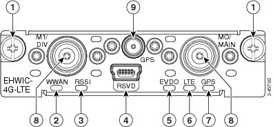
Figure 1 shows the EHWIC-4G-LTE-V front panel. Table 2 lists the EHWIC-4G-LTE-V ports and LED indicators and describes their behavior. The LEDs provide a visual indication of your available services.
Figure 1 Front Panel of the Cisco EHWIC-4G-LTE-V
Mounting Screws
LED—WWAN
LED—RSSI1
RSVD (reserved) port, USB 2.0 mini type B
LED—EVDO2
LED—LTE
LED—GPS3
Antenna Connectors—M1/DIV, M0/MAIN
Antenna Connector—GPS
1 RSSI = Received Signal Strength Indicator.
2 EVDO = Evolution Data Only.
3 GPS = Global Positioning System.
Table 2 Cisco EHWIC-4G-LTE-V Ports and LED Indicators
RSVD (Port)
The reserved (RSVD) diagnostic port is not required for normal activation or operation. This port supports modem debug or provisioning. See the "Modem Troubleshooting Using the Diagnostic Port" section in Configuring Cisco 4G LTE Wireless WAN EHWIC for details.
Antenna Connectors (Connectors)
M1/DIV—Diversity antenna connector, female TNC1 .
M0/MAIN—Main antenna connector, female TNC.
GPS—GPS antenna connector, female SMA2 .
See the "Supported Cisco Antennas and Cables" section for details.
WWAN (LED)
Indicates the EHWIC modem status.
Solid green—Indicates the modem is receiving power and is associated and authenticated but not receiving or transmitting data.
Fast green blink—Indicates the modem is receiving power and is associated and authenticated. The blink rate is proportional to the transmitted and received data rate.
Slow green blink—Indicates the modem is receiving power but is not associated or authenticated and is searching for service. Check the antenna, cable, SIM card, or the user account with your service provider.
Off—Indicates the modem is in reset mode.
RSSI (LED)
Indicates the level of signal strength received by the EHWIC software.
Solid green—Indicates a high RSSI (greater than -69 dBm).
Medium green blink—Indicates a medium-level RSSI (from -89 dBm to -69 dBm).
Slow green blink—Indicates a low-level RSSI (from -99 dBm to -89 dBm).
Off—Indicates the RSSI is less than -99 dBm. Check for proper antenna attachment. Adjust antenna placement and orientation.
Solid amber—Indicates no service is detected. Relocate the equipment.
EVDO (LED)
Indicates either HSDPA or EVDO is in service.
Solid green—Indicates HSDPA is in service.
Blinking green—Indicates EVDO service is in use.
Off—Indicates that neither HSDPA nor EVDO services are in use.
LTE (LED)
Indicates whether LTE is in service.
Solid green—Indicates LTE is in service.
Off—Indicates LTE service is not being used.
GPS (LED)
Indicates whether the GPS is in service.
Solid green—GPS is active.
Off—Indicates the GPS is not active or not detected.
1 TNC = Threaded Neill-Concelman.
2 SMA = Subminiature version A.
EHWIC-4G-LTE-A, EHWIC-4G-LTE-G, EHWIC-4G-LTE-JP, and EHWIC-4G-LTE-BE Ports and LEDs
Figure 2 shows the EHWIC-4G-LTE-A, EHWIC-4G-LTE-G, EHWIC-4G-LTE-JP, and EHWIC-4G-LTE-BE front panel. Table 3 lists the EHWIC-4G-LTE-A, EHWIC-4G-LTE-G, EHWIC-4G-LTE-JP, and EHWIC-4G-LTE-BE ports and LED indicators and describes their behavior.
Figure 2 Front Panel of Cisco EHWIC-4G-LTE-A, EHWIC-4G-LTE-G, EHWIC-4G-LTE-JP, and EHWIC-4G-LTE-BE
Mounting screws
LED—LTE
LED—WWAN
LED—GPS
LED—RSSI
Antenna connectors—M1/DIV, M0/MAIN
RSVD (reserved) port, USB 2.0 mini type B
Antenna connectors—GPS
LED—HSPA+
Table 3 Cisco EHWIC-4G-LTE-A, EHWIC-4G-LTE-G, EHWIC-4G-LTE-JP, and EHWIC-4G-LTE-BE Ports and LED Indicators
RSVD (Port)
The reserved (RSVD) diagnostic port is not required for normal activation or operation. This port supports modem debug or provisioning. See the "Modem Troubleshooting Using the Diagnostic Port" section in Configuring Cisco 4G LTE Wireless WAN EHWIC for details.
Antenna Connectors (Connector)
M1/DIV—Diversity antenna connector, female TNC1 .
M0/MAIN—Main antenna connector, female TNC.
GPS—GPS antenna connector, female SMA2 .
See the "Supported Cisco Antennas and Cables" section for details.
WWAN (LED)
Indicates the EHWIC modem status.
Solid green—Indicates the modem is receiving power and is associated and authenticated but not receiving or transmitting data.
Fast green blink—Indicates the modem is receiving power and is associated and authenticated. The blink rate is proportional to the transmitted and received data rate.
Slow green blink—Indicates the modem is receiving power but is not associated or authenticated and is searching for service. Check the antenna, cable, SIM card, or the user account with your service provider.
Off—Indicates the modem is in reset mode.
RSSI (LED)
Indicates the level of signal strength received by the EHWIC software.
Solid green—Indicates a high RSSI (greater than -69 dBm).
Medium green blink—Indicates a medium-level RSSI (from -89 dBm to -69 dBm).
Slow green blink—Indicates a low-level RSSI (from -99 dBm to -89 dBm).
Off—Indicates the RSSI is less than -99 dBm. Check for proper antenna attachment. Adjust antenna placement and orientation.
Solid amber—Indicates no service is detected. Relocate the equipment.
HSPA+ (LED)
Indicates HSPA+ is in service.
Solid green—Indicates HSPA+ is in service.
Off—Indicates that a non-HSPA+ is in service or that there is no service.
LTE (LED)
Indicates whether LTE is in service.
Solid green—Indicates LTE is in service.
Off—Indicates LTE service is not being used.
GPS (LED)
Indicates whether the GPS is in service.
Solid green—Indicates the GPS is active.
Off—Indicates the GPS is not active or not detected.
1 TNC = Threaded Neill-Concelman.
2 SMA = Subminiature version A.
Supported Cisco Antennas and Cables
Table 4 lists the Cisco antennas that are supported for use on the Cisco 4G WWAN EHWIC.
.
Table 4 Supported Antennas
4G-LTE-ANTM-D
Indoor 4G dipole omnidirectional
2 dBi
•
•
•
•
•
•
•
Multiband dipole antenna. For more information, see Cisco 4G/3G Omnidirectional Dipole Antenna (4G-LTE-ANTM-D).
4G-ANTM-OM-CM
Indoor ceiling-mount omni-directional
698 MHz-2690 MHz
Multiband omnidirectional ceiling-mount antenna. For more information, see Cisco 4G Indoor Ceiling-Mount Omnidirectional Antenna (4G-ANTM-OM-CM).
ANT-4G-OMNI-OUT-N
Multiband outdoor omnidirectional stick antenna
1.5 dBi
•
3.5 dBi
•
•
Multiband outdoor omnidirectional stick antenna. For more information, see Cisco Outdoor Omnidirectional Antenna for 2G/3G/4G Cellular (ANT-4G-OMNI-OUT-N).
ANT-4G-SR-OUT-TNC
Multiband outdoor omnidirectional saucer antenna
1.5 dBi (peak gain with 10-foot cable) or 0.8 dBi (peak gain with 15-foot cable)
•
3.7 dBi (peak gain with 10-foot cable) or 0.2 dBi (peak gain with 15-foot cable)
•
Low-profile outdoor saucer antenna. For more information, see Cisco Integrated 4G Low-Profile Outdoor Saucer Antenna (ANT-4G-SR-OUT-TNC).
4G-AE010-R
Extension base with integral 10-foot cable
0.7-6.0 GHz
This is the default antenna extension base. For more information, see Cisco Single-Port Antenna Stand for Multiband TNC Male-Terminated Portable Antenna (Cisco 4G-AE015-R, Cisco 4G-AE010-R).
4G-AE015-R
Extension base with integral 15-foot cable
0.7-6.0 GHz
Single-port antenna extension base with 15-foot cable. For more information, see Cisco Single-Port Antenna Stand for Multiband TNC Male-Terminated Portable Antenna (Cisco 4G-AE015-R, Cisco 4G-AE010-R).
4G-ACC-OUT-LA
Lightning Arrestor
800-2200 MHz
4G lightning arrestor kit for use on Cisco 4G wireless devices. For more information, see Cisco 4G Lightning Arrestor (4G-ACC-OUT-LA).
CGR-LA-NF-NF
Lightning Arrestor
800-2200 MHz
4G lightning arrestor kit for use on Cisco 4G wireless devices. For more information, see Lightning Arrestor for the Cisco 1240 Connected Grid Router.
Note
Note
Table 5 lists loss information and operating frequency levels for the ultra-low-loss (ULL) LMR 200 cables and LMR 400 cables available from Cisco for use with Cisco 4G Wireless WAN EHWICs and Cisco 4G Wireless WAN ISR platforms.
Table 5 Cisco Extension Cables for Use with 4G EHWICs
Loss4G-CAB-ULL-20
20 ft (6 m)
1.8 dB
700-2600 MHz
Black
Yes
4G-CAB-ULL-50
50 ft (15 m)
4.2 dB
700-2600 MHz
Black
Yes
4G-CAB-LMR240-25
25 ft (7.5 m)
2.1 dB @ 700 MHz
4.0 dB @ 2.6 GHz800-1000 MHz
1700-2600 MHzBlack
Yes
4G-CAB-LMR240-25N
25 ft (7.5 m)
2.1 dB @ 700 MHz
4.0 dB @ 2.6 GHz700-1000 MHz
1700-2600 MHzBlack
No
4G-CAB-LMR240-50
50 ft (15 m)
4.1 dB @ 700 MHz
7.4 dB @ 2.6 GHz800-1000 MHz
1700-2600 MHzBlack
Yes
4G-CAB-LMR240-75
75 ft (23 m)
6.1 dB @ 700 MHz
11.0 dB @ 2.6 GHz800-1000 MHz
1700-2600 MHzBlack
Yes
CAB-L400-20-TNC-N
20 ft (6 m)
1.75 dB
700-2600 MHz
Black
No
CAB-L400-50-TNC-N
50 ft (15 m)
4.0 dB
700-2600 MHz
Black
No
CAB-L400-20-N-N
20 ft (6 m)
2.75 dB
700-2600 MHz
Black
No
4G-AE010-R
10 ft (3 m)
1.4 dB @ 700 MHz
2.0 dB @ 1.9 GHz
2.1 dB @ 2.1 GHz
2.3 dB @ 2.5 GHz
2.4 dB @ 2.7 GHz700-2600 MHz
Black
No
4G-AE015-R
15 ft (4.6 m)
2.3 dB @ 700 MHz
3.3 dB @ 1.9 GHz
3.7 dB @ 2.1 GHz
4.0 dB @ 2.5 GHz700-2600 MHz
Black
No
1 Cable can be routed within building plenum spaces.
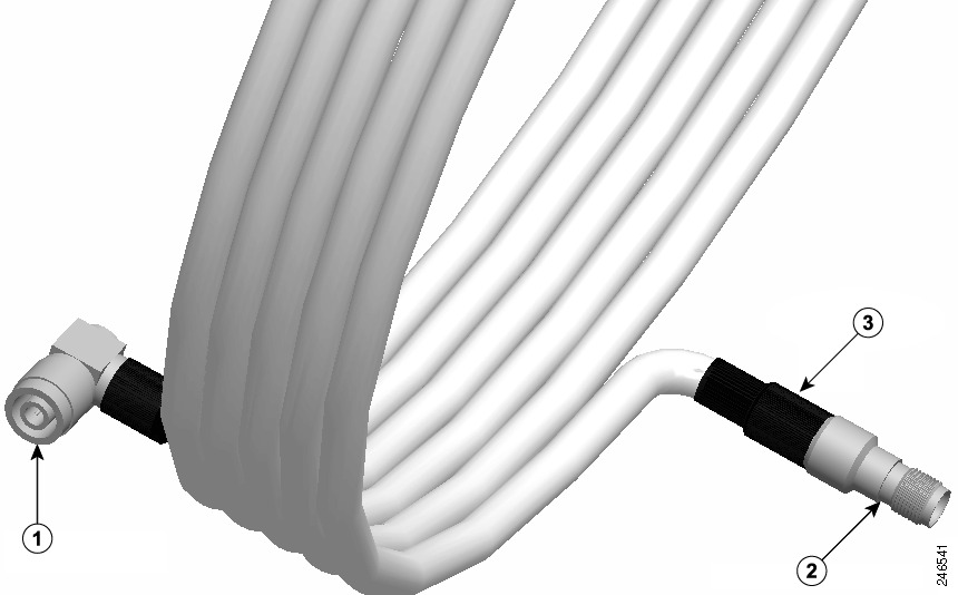
Figure 3 shows the ULL coaxial cable recommended for Cisco 4G Wireless WAN EHWICs.
Figure 3 Typical Coaxial Cable
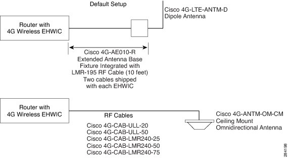
Figure 4 shows some antenna options for the Cisco 4G Wireless WAN EHWICs.
Figure 4 Antenna Options
Installing the SIM card on the Cisco EHWIC-4G-LTE
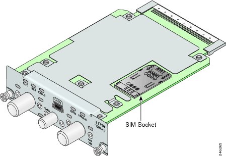
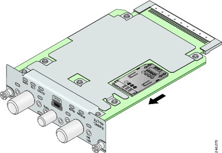
The SIM card socket is located on the bottom side of the EHWIC, as shown in Figure 5. The cover of the SIM card socket contains a slot into which the SIM card is installed.
Figure 5 Location of the SIM Socket on the Bottom Side of the EHWIC
Follow these steps to install the SIM card:
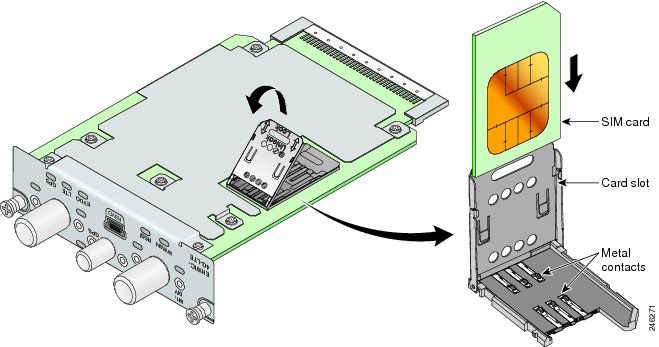
Step 1
Figure 6 Unlock the SIM Socket Cover
Step 2
Figure 7 Slide SIM card into Slot
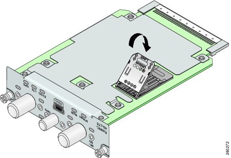
Step 3
Figure 8 Close the SIM Socket Cover
Step 4
Figure 9 Lock the SIM Socket Cover
Installing Cisco EHWIC-4G-LTE
See Installing Cisco Interface Cards in Cisco Access Routers for instructions on how to install a single-wide interface card in Cisco access routers.
Additional References
Related Documents
Regulatory, compliance, and safety information
•
http://www.cisco.com/en/US/docs/routers/access/interfaces/rcsi/IOHrcsi.html
Supported Cisco antennas and cables
•
•
http://www.cisco.com/en/US/docs/routers/access/wireless/hardware/notes/4G3G_ant.html
•
http://www.cisco.com/en/US/docs/routers/access/wireless/hardware/notes/antcm4gin.html
•
•
•
http://www.cisco.com/en/US/docs/routers/access/wireless/hardware/notes/4Gantex15-10r.html
•
http://www.cisco.com/en/US/docs/routers/access/wireless/hardware/notes/4Glar.html
•
•
http://www.cisco.com/en/US/docs/routers/access/interfaces/
software/feature/guide/EHWIC-4G-LTESW.html
Technical Assistance
Cisco and the Cisco logo are trademarks or registered trademarks of Cisco and/or its affiliates in the U.S. and other countries. To view a list of Cisco trademarks, go to this URL: www.cisco.com/go/trademarks. Third-party trademarks mentioned are the property of their respective owners. The use of the word partner does not imply a partnership relationship between Cisco and any other company. (1110R)
Any Internet Protocol (IP) addresses and phone numbers used in this document are not intended to be actual addresses and phone numbers. Any examples, command display output, network topology diagrams, and other figures included in the document are shown for illustrative purposes only. Any use of actual IP addresses or phone numbers in illustrative content is unintentional and coincidental.
© 2011-2013 Cisco Systems, Inc. All rights reserved.