Feedback Feedback
|
Table Of Contents
Alarm Interface Controller Patch Panel Installation Guide
Mounting the Strain Relief Bar
Obtaining Technical Assistance
Alarm Interface Controller Patch Panel Installation Guide
AIC-SGL-PNL(=), AIC-DBL-PNL(=)
This guide describes how to install the alarm interface controller (AIC) patch panel and how to connect it to the AIC network module for Cisco 2600 series, Cisco 3640, and Cisco 3660 modular access routers and the Cisco MWR 1941-DC Mobile Wireless Edge Router. It contains the following sections:
•
Obtaining Technical Assistance
Use this document with the documents listed in "Related Documents" section
Overview
The patch panel supplies power to the alarm circuits connected to an AIC network module, by means of a -48V DC circuit bridged to the alarm circuit. Current flows when the loop is closed by an alarm. The network module detects this current and sends a message to the network operating center.
There are two models of AIC patch panel:
•
•
The AIC network module is shown in Figure 7.
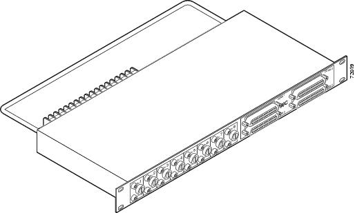
Figure 1 AIC-SGL-PNL Patch Panel
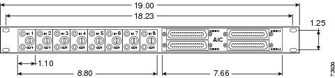
Figure 2 AIC-SGL-PNL Patch Panel Dimensions and Front View
Figure 3 AIC-SGL-PNL Patch Panel, Rear View
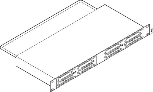
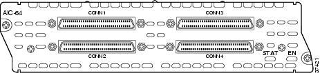
Figure 4 AIC-DBL-PNL Patch Panel
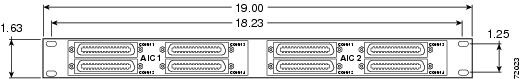
Figure 5 AIC-DBL-PNL Patch Panel, Front View
Figure 6 AIC-DBL-PNL Patch Panel, Rear View
Figure 7 Alarm Interface Controller Network Module
Table 1 gives temperature specifications for the patch panel.
Safety Information
Read the following safety information before performing any installation or connection procedure.
Warning
Warning
•
•
•
Warning
Caution
Warning
Caution
Caution
42.4 Vpk or 60 Vdc and it should be limited/fused power source. For more details on Class 2 circuits, refer to the National Electrical Code/Canadian Electrical Code. This does not apply to analog input/output terminal strip numbers 1-8 on the AIC-SGL-PNL patch panel.
Caution
Caution
Caution
Required Tools and Equipment
Installation might require some tools and equipment that are not provided as standard equipment with the router. Following are the tools and parts required for a typical installation:
•
•
Mounting the Patch Panel
You can mount the patch panel in a 19-inch rack using the built-in brackets.
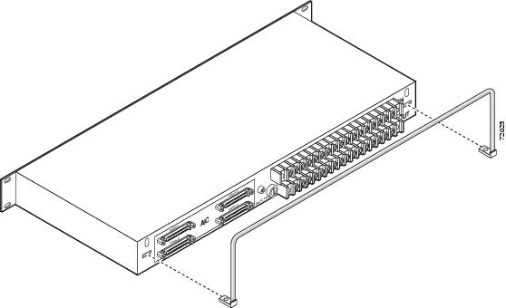
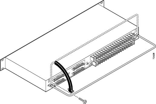
Mounting the Strain Relief Bar
Mount the strain relief bar as shown in Figure 8 and Figure 9.
Figure 8 Inserting the Strain Relief Bar
Figure 9 Positioning the Strain Relief Bar
Electrical Connections
This section explains how to ground the patch panel and how to connect electrical power.
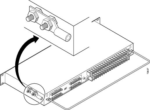
Grounding
The patch panel comes with a grounding lug preinstalled. To ground the lug, follow these steps:
Step 1
Warning
Step 2
Figure 10 Grounding Lug
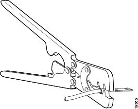
Step 3
Step 4
Figure 11 Crimping the Lug Around the Wire
Step 5
Step 6
Caution
Step 7
Connecting Electrical Power
This section explains how to connect electrical power to the patch panel.
The AIC-SGL-PNL patch panel provides terminals for eight analog circuits. Power is provided to each monitored circuit by the IN terminal block on the back of the patch panel. Power is taken from each monitored circuit by the OUT terminal block located below the IN terminal block.
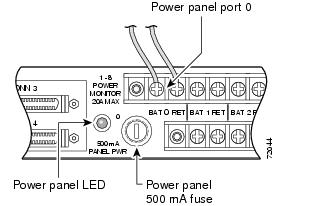
The AIC-SGL-PNL patch panel must also have -48 VDC connected to the first pair of terminals (port 0) on the IN terminal block. This voltage is independent of other feeds being monitored and is used to operate the detection circuits. The 500 mA fuse for port 0 is shown in Figure 12.
The AIC-DBL-PNL patch panel does not provide monitoring of analog circuits. This patch panel must have -48 VDC connected to the terminal block on the back of the patch panel.
Follow this procedure to wire the terminal block:
Warning
Step 1
Step 2
Step 3
Step 4
Figure 12 -48 VDC Connection
Warning
Caution
8.2 ± 0.4 inch-lb.
Warning
Warning
Warning
Connecting Network Cables
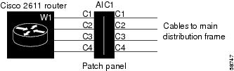
Patch panel connections to the AIC network module are shown schematically in Figure 13. The four connectors of each AIC network module connect to four input connectors on the patch panel. The output connectors of the patch panel are cabled to the customer's main distribution frame (MDF). The patch panel looks transparent to the AIC network module.
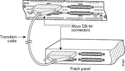
An AIC network module provides four interfaces using 50-pin SCSI II receptacles. To connect the
SCSI II connectors on the front of the patch panel to the network module, use cables that have male Micro DB-50 connectors at both ends, with all conductors straight-wired. A set of four eight-foot male-to-male SCSI II interface cables is orderable separately, product number CAB-AIC-008. Ports are numbered from right to left and from bottom to top, as labeled on the module's rear panel (see Figure 7).To connect the Telco connectors on the back of the patch panel to the main distribution frame, use RJ-21 Telco connector serial cables (50-pin male).
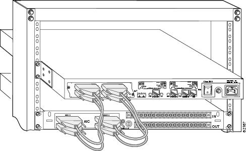
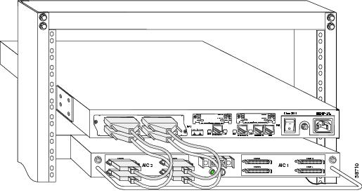
Figure 14 shows connections from the AIC network module faceplate to a patch panel. Figure 15 shows connections to the AIC-SGL-PNL patch panel. Figure 16 shows connections to the AIC-DBL-PNL patch panel.
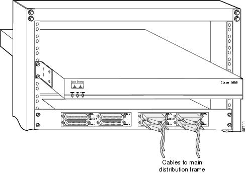
Figure 17 shows patch panel connections to the main distribution frame. These connections should be made with AWG 24 copper wire or equivalent.
Figure 13 AIC Network Module Connection Diagram
Figure 14 AIC Network Module Faceplate Connections
Figure 15 AIC Network Module Connected to the AIC-SGL-PNL Patch Panel
Figure 16 AIC Network Module Connected to the AIC-DBL-PNL Patch Panel
Figure 17 AIC-DBL-PNL Patch Panel Connected to MDF
Patch Panel LEDs
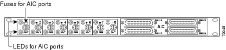
Each monitored analog circuit on the AIC-SGL-PNL patch panel has a green POWER IN LED and a green POWER OUT LED on the front of the patch panel. The POWER IN LED is on when voltage is present before the fuse. The POWER OUT LED is on when voltage is present after the fuse. See Figure 18.
Figure 18 Patch Panel LEDs and Fuses
Both models of patch panel have a green PANEL POWER LED on the back. This LED shows the status of the -48 VDC input used to operate the detection circuits.
Patch Panel Pinouts
Table 2 shows pinouts for the AIC-SGL-PNL patch panel. Table 3 shows connector 3 voltage monitor pinouts for the AIC-SGL-PNL patch panel. Table 4 shows pinouts for the AIC-DBL-PNL patch panel.
Table 2 AIC-SGL-PNL Patch Panel Connector Pinouts
1
Alarm neg1
Alarm neg 26
Alarm neg 51
Control common 1
26
Alarm pos 1
Alarm pos 26
Alarm pos 51
Control N.O. 1
2
Alarm neg 2
Alarm neg 27
Alarm neg 52
Control common 2
27
Alarm pos 2
Alarm pos 27
Alarm pos 52
Control N.O. 2
3
Alarm neg 3
Alarm neg 28
Alarm neg 53
Control common 3
28
Alarm pos 3
Alarm pos 28
Alarm pos 53
Control N.O. 3
4
Alarm neg 4
Alarm neg 29
Alarm neg 54
Control common 4
29
Alarm pos 4
Alarm pos 29
Alarm pos 54
Control N.O. 4
5
Alarm neg 5
Alarm neg 30
Alarm neg 55
Control common 5
30
Alarm pos 5
Alarm pos 30
Alarm pos 55
Control N.O. 5
6
Alarm neg 6
Alarm neg 31
Alarm neg 56
Control common 6
31
Alarm pos 6
Alarm pos 31
Alarm pos 56
Control N.O. 6
7
Alarm neg 7
Alarm neg 32
See Table 3
Control common 7
32
Alarm pos 7
Alarm pos 32
See Table 3
Control N.O. 7
8
Alarm neg 8
Alarm neg 33
See Table 3
Control common 8
33
Alarm pos 8
Alarm pos 33
See Table 3
Control N.O. 8
9
Alarm neg 9
Alarm neg 34
See Table 3
Control common 9
34
Alarm pos 9
Alarm pos 34
See Table 3
Control N.O. 9
10
Alarm neg 10
Alarm neg 35
See Table 3
Control common 10
35
Alarm pos 10
Alarm pos 35
See Table 3
Control N.O. 10
11
Alarm neg 11
Alarm neg 36
See Table 3
Control common 11
36
Alarm pos 11
Alarm pos 36
See Table 3
Control N.O. 11
12
Alarm neg 12
Alarm neg 37
See Table 3
Control common 12
37
Alarm pos 12
Alarm pos 37
See Table 3
Control N.O. 12
13
Alarm neg 13
Alarm neg 38
See Table 3
Control common 13
38
Alarm pos 13
Alarm pos 38
See Table 3
Control N.O. 13
14
Alarm neg 14
Alarm neg 39
See Table 3
Control common 14
39
Alarm pos 14
Alarm pos 39
See Table 3
Control N.O. 14
15
Alarm neg 15
Alarm neg 40
—
Control common 15
40
Alarm pos 15
Alarm pos 40
—
Control N.O. 15
16
Alarm neg 16
Alarm neg 41
—
Control common 16
41
Alarm pos 16
Alarm pos 41
—
Control N.O. 16
17
Alarm neg 17
Alarm neg 42
—
—
42
Alarm pos 17
Alarm pos 42
—
—
18
Alarm neg 18
Alarm neg 43
—
—
43
Alarm pos 18
Alarm pos 43
—
—
19
Alarm neg 19
Alarm neg 44
—
—
44
Alarm pos 19
Alarm pos 44
—
—
20
Alarm neg 20
Alarm neg 45
—
—
45
Alarm pos 20
Alarm pos 45
—
—
21
Alarm neg 21
Alarm neg 46
—
—
46
Alarm pos 21
Alarm pos 46
—
—
22
Alarm neg 22
Alarm neg 47
—
—
47
Alarm pos 22
Alarm pos 47
—
—
23
Alarm neg 23
Alarm neg 48
—
—
48
Alarm pos 23
Alarm pos 48
—
—
24
Alarm neg 24
Alarm neg 49
—
—
49
Alarm pos 24
Alarm pos 49
—
—
25
Alarm neg 25
Alarm neg 50
—
—
50
Alarm pos 25
Alarm pos 50
—
—
Related Documents
For additional information, see the following documents:
•
•
•
•
•
•
•
•
•
Obtaining Documentation
The following sections explain how to obtain documentation from Cisco Systems.
World Wide Web
You can access the most current Cisco documentation on the World Wide Web at the following URL:
Translated documentation is available at the following URL:
http://www.cisco.com/public/countries_languages.shtml
Ordering Documentation
Cisco documentation is available in the following ways:
•
http://www.cisco.com/cgi-bin/order/order_root.pl
•
http://www.cisco.com/go/subscription
•
Documentation Feedback
If you are reading Cisco product documentation on Cisco.com, you can submit technical comments electronically. Click Leave Feedback at the bottom of the Cisco Documentation home page. After you complete the form, print it out and fax it to Cisco at 408 527-0730.
You can e-mail your comments to bug-doc@cisco.com.
To submit your comments by mail, use the response card behind the front cover of your document, or write to the following address:
Cisco Systems
Attn: Document Resource Connection
170 West Tasman Drive
San Jose, CA 95134-9883We appreciate your comments.
Obtaining Technical Assistance
Cisco provides Cisco.com as a starting point for all technical assistance. Customers and partners can obtain documentation, troubleshooting tips, and sample configurations from online tools by using the Cisco Technical Assistance Center (TAC) Web Site. Cisco.com registered users have complete access to the technical support resources on the Cisco TAC Web Site.
Cisco.com
Cisco.com is the foundation of a suite of interactive, networked services that provides immediate, open access to Cisco information, networking solutions, services, programs, and resources at any time, from anywhere in the world.
Cisco.com is a highly integrated Internet application and a powerful, easy-to-use tool that provides a broad range of features and services to help you to
•
•
•
•
•
You can self-register on Cisco.com to obtain customized information and service. To access Cisco.com, go to the following URL:
Technical Assistance Center
The Cisco TAC is available to all customers who need technical assistance with a Cisco product, technology, or solution. Two types of support are available through the Cisco TAC: the Cisco TAC Web Site and the Cisco TAC Escalation Center.
Inquiries to Cisco TAC are categorized according to the urgency of the issue:
•
•
•
•
Which Cisco TAC resource you choose is based on the priority of the problem and the conditions of service contracts, when applicable.
Cisco TAC Web Site
The Cisco TAC Web Site allows you to resolve P3 and P4 issues yourself, saving both cost and time. The site provides around-the-clock access to online tools, knowledge bases, and software. To access the Cisco TAC Web Site, go to the following URL:
All customers, partners, and resellers who have a valid Cisco services contract have complete access to the technical support resources on the Cisco TAC Web Site. The Cisco TAC Web Site requires a Cisco.com login ID and password. If you have a valid service contract but do not have a login ID or password, go to the following URL to register:
http://www.cisco.com/register/
If you cannot resolve your technical issues by using the Cisco TAC Web Site, and you are a Cisco.com registered user, you can open a case online by using the TAC Case Open tool at the following URL:
http://www.cisco.com/tac/caseopen
If you have Internet access, it is recommended that you open P3 and P4 cases through the Cisco TAC Web Site.
Cisco TAC Escalation Center
The Cisco TAC Escalation Center addresses issues that are classified as priority level 1 or priority level 2; these classifications are assigned when severe network degradation significantly impacts business operations. When you contact the TAC Escalation Center with a P1 or P2 problem, a Cisco TAC engineer will automatically open a case.
To obtain a directory of toll-free Cisco TAC telephone numbers for your country, go to the following URL:
http://www.cisco.com/warp/public/687/Directory/DirTAC.shtml
Before calling, please check with your network operations center to determine the level of Cisco support services to which your company is entitled; for example, SMARTnet, SMARTnet Onsite, or Network Supported Accounts (NSA). In addition, please have available your service agreement number and your product serial number.
CCIP, CCSP, the Cisco Arrow logo, the Cisco Powered Network mark, Cisco Unity, Follow Me Browsing, FormShare, and StackWise are trademarks of Cisco Systems, Inc.; Changing the Way We Work, Live, Play, and Learn, and iQuick Study are service marks of Cisco Systems, Inc.; and Aironet, ASIST, BPX, Catalyst, CCDA, CCDP, CCIE, CCNA, CCNP, Cisco, the Cisco Certified Internetwork Expert logo, Cisco IOS, the Cisco IOS logo, Cisco Press, Cisco Systems, Cisco Systems Capital, the Cisco Systems logo, Empowering the Internet Generation, Enterprise/Solver, EtherChannel, EtherSwitch, Fast Step, GigaStack, Internet Quotient, IOS, IP/TV, iQ Expertise, the iQ logo, iQ Net Readiness Scorecard, LightStream, MGX, MICA, the Networkers logo, Networking Academy, Network Registrar, Packet, PIX, Post-Routing, Pre-Routing, RateMUX, Registrar, ScriptShare, SlideCast, SMARTnet, StrataView Plus, Stratm, SwitchProbe, TeleRouter, The Fastest Way to Increase Your Internet Quotient, TransPath, and VCO are registered trademarks of Cisco Systems, Inc. and/or its affiliates in the U.S. and certain other countries.
All other trademarks mentioned in this document or Web site are the property of their respective owners. The use of the word partner does not imply a partnership relationship between Cisco and any other company. (0304R)
Copyright © 2002-2003, Cisco Systems, Inc. All rights reserved.
Printed in the USA on recycled paper containing 10% postconsumer waste.