Downloads |
 Feedback Feedback
|
Table Of Contents
Obtaining Additional Publications and Information
Site Preparation and Unpacking
Prepare for Workbench or Tabletop Installation
Prepare for Rack-Mount Installation
Install the GBIC or SFP Module
Attach the Rack-Mount Brackets—Chassis Front-Mounted
Attach the Cable-Management Brackets
Chassis Ground Connection Installation
Connect the Router to the Network
Console and Auxiliary Port Cable Connections
Gigabit Ethernet and Fast Ethernet Port Connections
Fast Ethernet Management Port on the NSE-100 or NSE-150
Gigabit Ethernet RJ-45 Ports on the NPE-G100
Intra-Building Lightning Protection
GBIC and SFP Module Cabling and Connection Equipment
Connect the Optical Fiber Cables to the GBIC in the NSE-100
Connect the Optical Fiber Cables to an SFP Module in the NPE-G100 or NSE-150
Attach the Mode-Conditioning Patch Cord
Observe System Startup and Perform a Basic Configuration
Perform a Basic Configuration Using the Setup Facility
Save the Running Configuration to NVRAM
Check the Running Configuration Settings
View Your System Configuration
Perform Complex Configurations
Replace or Recover a Lost Password
Which prompt do you see on the console?
Router in Boot Mode: Router (boot)>
Cisco Technical Support & Documentation Website
Quick Start Guide
Cisco 7304 Quick Start Guide
1 Documentation and Resources
Documentation for the Cisco 7304 router is online and orderable. For detailed hardware installation instructions, refer to the online Cisco 7304 Installation and Configuration Guide. Refer to the following online documents for titles and links to related documentation for installation and replacement of parts (including line cards and port adapters), regulatory compliance information, and troubleshooting information and tools.
•
All Cisco 7304 documentation—See the Cisco 7304 Internet Router Documentation Roadmap at http://www.cisco.com/univercd/cc/td/doc/product/core/cis7300/3515.htm.
•
•
Documentation Survey
Is Cisco documentation helpful? Click here or go to http://forums.cisco.com/eforum/servlet/viewsflash?cmd=showform&pollid=rtgdoc01!rtgdoc to give us your feedback
Obtaining Documentation
Cisco documentation and additional literature are available on Cisco.com. Cisco also provides several ways to obtain technical assistance and other technical resources. These sections explain how to obtain technical information from Cisco Systems.
Cisco.com
You can access the most current Cisco documentation at this URL:
http://www.cisco.com/techsupport
You can access the Cisco website at this URL:
You can access international Cisco websites at this URL:
http://www.cisco.com/public/countries_languages.shtml
Product Documentation DVD
The Product Documentation DVD is a comprehensive library of technical product documentation on a portable medium. The DVD enables you to access multiple versions of installation, configuration, and command guides for Cisco hardware and software products. With the DVD, you have access to the same HTML documentation that is found on the Cisco website without being connected to the Internet. Certain products also have .PDF versions of the documentation available.
The Product Documentation DVD is available as a single unit or as a subscription. Registered Cisco.com users (Cisco direct customers) can order a Product Documentation DVD (product number DOC-DOCDVD= or DOC-DOCDVD=SUB) from Cisco Marketplace at this URL:
http://www.cisco.com/go/marketplace/
Ordering Documentation
Registered Cisco.com users may order Cisco documentation at the Product Documentation Store in the Cisco Marketplace at this URL:
http://www.cisco.com/go/marketplace/
Nonregistered Cisco.com users can order technical documentation from 8:00 a.m. to 5:00 p.m. (0800 to 1700) PDT by calling 1 866 463-3487 in the United States and Canada, or elsewhere by calling 011 408 519-5055. You can also order documentation by e-mail at tech-doc-store-mkpl@external.cisco.com or by fax at 1 408 519-5001 in the United States and Canada, or elsewhere at 011 408 519-5001.
Documentation Feedback
You can rate and provide feedback about Cisco technical documents by completing the online feedback form that appears with the technical documents on Cisco.com.
You can submit comments about Cisco documentation by using the response card (if present) behind the front cover of your document or by writing to the following address:
Cisco Systems
Attn: Customer Document Ordering
170 West Tasman Drive
San Jose, CA 95134-9883We appreciate your comments.
Obtaining Additional Publications and Information
Information about Cisco products, technologies, and network solutions is available from various online and printed sources.
The Cisco Product Quick Reference Guide is a handy, compact reference tool that includes brief product overviews, key features, sample part numbers, and abbreviated technical specifications for many Cisco products that are sold through channel partners. It is updated twice a year and includes the latest Cisco offerings. To order and find out more about the Cisco Product Quick Reference Guide, go to this URL:
Cisco Marketplace provides a variety of Cisco books, reference guides, documentation, and logo merchandise. Visit Cisco Marketplace, the company store, at this URL:
http://www.cisco.com/go/marketplace/
Cisco Press publishes a wide range of general networking, training and certification titles. Both new and experienced users will benefit from these publications. For current Cisco Press titles and other information, go to Cisco Press at this URL:
Packet magazine is the Cisco Systems technical user magazine for maximizing Internet and networking investments. Each quarter, Packet delivers coverage of the latest industry trends, technology breakthroughs, and Cisco products and solutions, as well as network deployment and troubleshooting tips, configuration examples, customer case studies, certification and training information, and links to scores of in-depth online resources. You can access Packet magazine at this URL:
Internet Protocol Journal is a quarterly journal published by Cisco Systems for engineering professionals involved in designing, developing, and operating public and private internets and intranets. You can access the Internet Protocol Journal at this URL:
Networking products offered by Cisco Systems, as well as customer support services, can be obtained at this URL:
http://www.cisco.com/en/US/products/index.html
Networking Professionals Connection is an interactive website for networking professionals to share questions, suggestions, and information about networking products and technologies with Cisco experts and other networking professionals. Join a discussion at this URL:
http://www.cisco.com/discuss/networking
World-class networking training is available from Cisco. You can view current offerings at this URL:
http://www.cisco.com/en/US/learning/index.html
2 Prepare for Installation
This section contains warnings, information about tools and parts, site preparation information, and information for workbench or tabletop installation and rack-mount installation.
Warning
Warning
Warning
Warning
Warning
Warning
Warning
Warning
Before beginning this router installation, read the Regulatory Compliance and Safety Information for the Cisco 7304 Internet Router document.
Site Preparation and Unpacking
•
•
•
•
Tools and Parts
Use the following list of tools and parts as a checklist for preparing for installing the Cisco 7304 router:
•
•
•
•
•
•
•
•
•
•
•
–
–
–
–
–
•
–
•
–
–
Prepare for Workbench or Tabletop Installation
For a workbench or tabletop installation, verify the following before installing the router:
•
•
•
•
•
For cable-management bracket installation instructions, see the "Attach the Cable-Management Brackets" section.
Prepare for Rack-Mount Installation
Make these decisions before you begin the rack-mounting tasks:
•
•
•
3 Install the External Options
This section provides installation instructions for the CompactFlash Disk and the GBIC and SFP module.
Install the CompactFlash Disk
Figure 1 Inserting and Removing the CompactFlash Disk
Insert the CompactFlash Disk into the CompactFlash Disk slot with the label with the vendor name and memory size facing up. The CompactFlash Disk protrudes when completely inserted.
To eject a CompactFlash Disk, press the ejector button—located on the right side of the slot—until the CompactFlash Disk is free of the connector at the rear of the PC Card slot. Remove the CompactFlash Disk from the slot and place it in an antistatic bag.
About the CompactFlash Disk
The CompactFlash Disk supports online insertion and removal (OIR). For more information on CompactFlash Disks, see Appendix C of the Cisco 7304 Installation and Configuration Guide at http://www.cisco.com/univercd/cc/td/doc/product/core/cis7300/install/13279fd.htm
Install the GBIC or SFP Module
Warning
Warning
Warning
About the GBIC and SFP Module
The Gigabit Interface Converter (GBIC) and small form-factor pluggable (SFP) module support online insertion and removal (OIR). For more information on the GBIC or SFP type, technologies, and models, see the Cisco 7304 Installation and Configuration Guide.
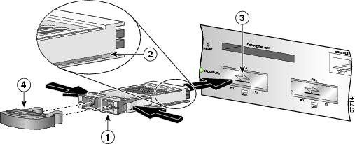
Figure 2 Installing a Gigabit Interface Converter in the NSE-100
Step 1
Note
Step 2
Note
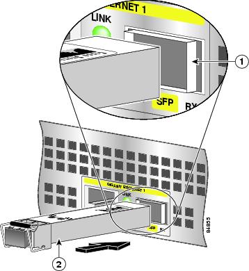
Figure 3 Inserting an SFP Module in the NPE-G100 or the NSE-150
The NSE-150 and NPE-G100 use only Gigabit Ethernet SFP modules. A variety of latch types are available. Figure 3 shows one type. For more information about SFP types, technologies, models, and cabling specifications, see the Cisco 7304 Installation and Configuration Guide.
Step 1
Step 2
Warning
Note
Step 3
Step 4
Note
4 Rack-Mount the Router
This section provides information for rack-mounting the router.
Attach the Rack-Mount Brackets—Chassis Front-Mounted
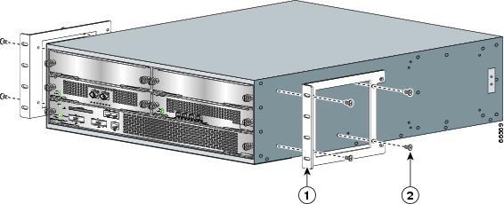
Figure 4 Attaching the Rack-Mount Brackets to the Front of the Chassis
Rack-mount bracket
Eight 8-18 x .37-inch screws—19-inch rack
Eight 8 x .755-inch screws—21-23-inch rack
The rack-mount brackets ship installed on the router. These instructions are provided if you want to change the position of the brackets or reattach them. Depending on how the rack-mount brackets are attached to the chassis, the chassis either protrudes from the rack or is recessed in the rack.
Step 1
Step 2
Step 3
Step 4
Attach the Cable-Management Brackets
Figure 5 Attaching the Cable-Management Brackets
Step 1
Step 2
Step 3
Go to the "Four-Post Rack Installation" section or the "Two-Post Rack Installation" section.
Four-Post Rack Installation
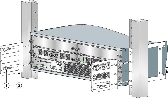
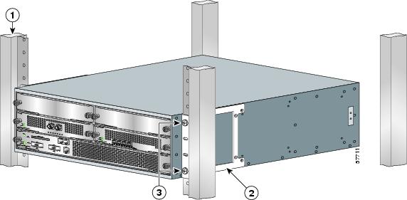
Figure 6 Installing the Cisco 7304 Router in a Four-Post Rack
Note
Step 1
Step 2
Step 3
Step 4
Step 5
Step 6
Two-Post Rack Installation
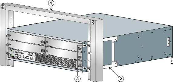
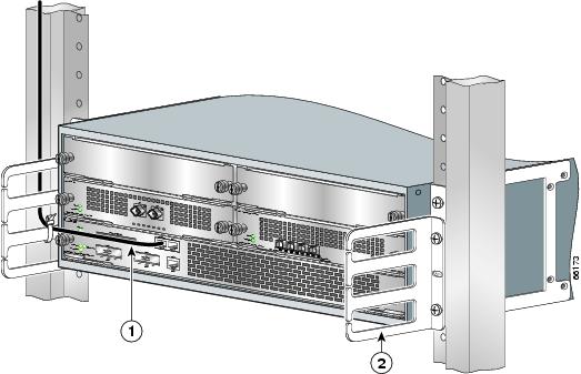
Figure 7 Installing the Cisco 7304 Router in a Two-Post or Telco Rack
Note
Step 1
Step 2
Step 3
Step 4
Step 5
Step 6
Chassis Ground Connection Installation
Warning
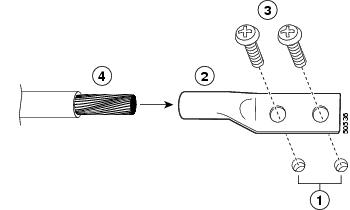
Figure 8 Attaching the Grounding Lug and Wire to the Chassis
Note
Step 1
Step 2
Step 3
Step 4
Step 5
Step 6
Step 7
5 Connect the Router to the Network
The NSE-100, NSE-150, and NPE-G100 are the processing engines available for the Cisco 7304 router. Each processing engine has a different number of Gigabit Ethernet interfaces and different Gigabit Ethernet Gigabit Interface Converter port types (GBIC or SFP). In addition, the NSE-100 and NSE-150 have a Fast Ethernet management port; the NPE-G100 does not. The console port and auxiliary port are the same on all three processing engines.
This section provides information about processing engine cables and ports and attaching the router to the network. Use the information about the NPE-G100, NSE-100, or the NSE-150, whichever is appropriate for your installation.
Figure 9 Attaching the Console and Auxiliary Port Cables
Console port
Cable to console terminal or DTE
Auxiliary port
Cable to modem or DCE
RJ-45 connector
Console and Auxiliary Port Cable Connections
Note
Step 1
Step 2
Note
Gigabit Ethernet and Fast Ethernet Port Connections
Your Cisco 7304 router has either one or two NSE-100s, one or two NSE-150s, or one or two NPE-G100s installed. Use this section to connect the appropriate cables to the appropriate processing engine.
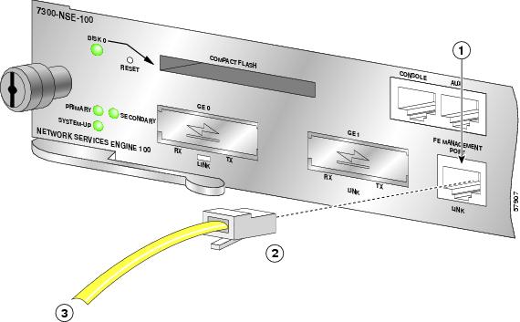
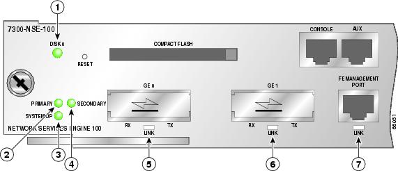
Fast Ethernet Management Port on the NSE-100 or NSE-150
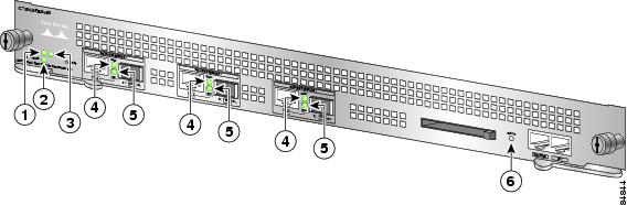
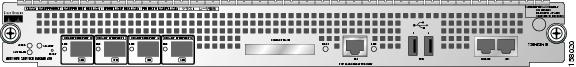
The NSE-100 has one two-port Gigabit Ethernet interface and one Fast Ethernet Management port. The NPE-G100 has three Gigabit Ethernet interfaces, with three RJ-45 10/100/1000 ports and three SFP ports; any three are available at any time. The NSE-150 has four SFP ports that are all available at any time and a Fast Ethernet Management port.
For more information, see the online Cisco 7304 Installation and Configuration Guide.
Figure 10 Attaching the Fast Ethernet Cable (NSE-100 Example)
Warning
To identify the cable type, hold the two ends of the cable next to each other so you can see the colored wires inside the ends. The straight-through wire type has colored wires in the same sequence at both ends. In the crossover wire type, the first colored wire at the far left is the third colored wire at the other end. The second colored wire at the far left is the sixth colored wire at the other end.
Attach RJ-45 Fast Ethernet cables to the appropriate connector.
Note
Gigabit Ethernet RJ-45 Ports on the NPE-G100
Intra-Building Lightning Protection
Shielded cables, which are grounded at both ends, are required to be used on the 10/100/1000 Ethernet/Fast Ethernet /Gigabit Ethernet (RJ-45) port in order to be in compliance with requirement R4-11 in GR-1089-Core for a Central Office environment. This is not a requirement for customer premise installations.
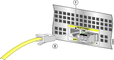
Figure 11 Attaching the RJ-45 Port Gigabit Ethernet Cables
Attach one, two, or three Gigabit Ethernet 10/100/1000 cables to the Gigabit Ethernet RJ-45 port 0, port 1, or port 2.
Warning
GBIC and SFP Module Cabling and Connection Equipment
The Cisco 7304 has three processing engines, the NSE-100, the NSE-150, and the NPE-G100. The NSE-100 uses GBICs GBIC-SX or WS-G5484, GBIC-LX/LH or WS-G5486, GBIC-ZX or WS-G5487, the CWDM GBICs, and WS-G5483= . The NPE-G100 uses SFPs GLC-SX-MM, GLC-LH-SM, GLC-ZX-SM, and the CWDM SFPs. The NSE-150 uses the CWDM SFPs, GLC-BX-D, GLC-BX-U, GLC-LH-SM, GLC-SX-MM, GLC-T, GLC-ZX-SM, SFP-GE-L, SFP-GE-S, and SFP-GE-Z.
The Gigabit Interface Converter (GBIC) port is a 1000-Mbps optical interface in the form of an SC-type duplex port that supports IEEE 802.3z interfaces compliant with the 1000BASEX standard.
The Gigabit Ethernet SFP port is a 1000-Mbps optical interface in the form of an LC-type duplex port that supports IEEE 802.3z interfaces compliant with the 1000BASEX standard.
For cabling distances, specifications, and other information, see the online Cisco 7304 Router Installation and Configuration Guide at http://www.cisco.com/univercd/cc/td/doc/product/core/cis7300/install/index.htm.
Note
Warning
Warning
Warning
Connect the Optical Fiber Cables to the GBIC in the NSE-100
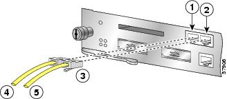
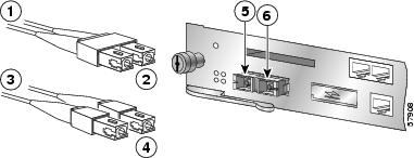
Figure 12 Inserting the Gigabit Ethernet Optical Fiber Cables into the NSE-100 GBIC
To external 1000BASEX network
2 simplex connectors
1 duplex connector (TX and RX)
RX
To external 1000BASEX network
TX
Note
Warning
Step 1
Step 2
Two cables are required for simplex connectors, one cable for transmit (TX) and one for receive (RX).
One cable that has both TX and RX connectors is required for duplex connectors.
Caution
Connect the Optical Fiber Cables to an SFP Module in the NPE-G100 or NSE-150
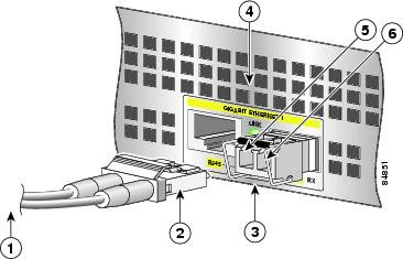
Figure 13 Inserting the Gigabit Ethernet Optical Fiber Cable in the SFP Module (NPE-G100 Example)
To external 1000BASEX network
Gigabit Ethernet SFP slot 1
Duplex connector (TX and RX)
TX (Gigabit Ethernet SFP slot 1)
Gigabit Ethernet SFP module
RX (Gigabit Ethernet SFP slot 1)
Step 1
Warning
Step 2
•
•
Attach the Mode-Conditioning Patch Cord
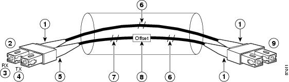
Figure 14 Attaching the Mode-Conditioning Patch Cord (LC-Type Connectors Shown)
Beige color identifier
Multimode bar
To GE interface
Single-mode bar
RX
Offset
TX
To cable plant
Blue color identifier
Step 1
Step 2
Note
A mode-conditioning patch cord can be used with the GBIC-LX/LH or WS-G5486, or GLC-LH-SM to allow reliable laser transmission between the single-mode laser source on the GBIC or SFP module and a multimode optical fiber cable.
Line Card Cable Connections
The instructions for connecting the cables for each line card, port adapter, or SPA installed in the Cisco 7304 router are in the respective online notes for each line card. Refer to the documents at http://www.cisco.com/univercd/cc/td/doc/product/core/cis7300/3531.htm
Cable Management
Figure 15 Inserting the Cables Through the Cable-Management Brackets
If you have not already done so, run the line card cables, port adapter cables, SPA cables, and input/output cables through the cable-management brackets.
6 Start the System
Warning
This section provides instructions for attaching the power cables to the router and powering on the router.
The Cisco 7304 router comes with either an AC or DC power supply. A redundant AC or DC power supply option is available. Using an AC and DC power supply in the same chassis simultaneously is not supported.
Connect AC-Input Power
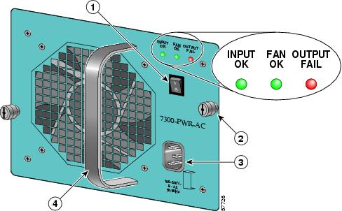
Figure 16 Attaching the AC Power Cable
Step 1
Step 2
Connect DC-Input Power
Warning
Warning
Note
Note
Step 1
Step 2
Note
Step 3
Note
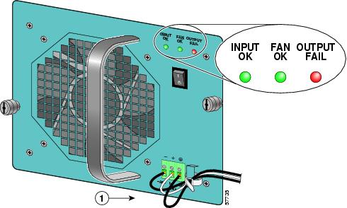
Figure 17 Attaching the Wires to the DC Power Receptacles
Step 4
Step 5
Note
Step 6
Note
Step 7
Note
Observe System Startup and Perform a Basic Configuration
Check conditions prior to system startup:
Step 1
Step 2
Step 3
Step 4
Start the Router
Step 1
Step 2
Step 3
Step 4
The following illustrations and tables provide information about the NSE-100, NSE-150, and NPE-G100 LEDs as the system starts.
Figure 18 Identifying LEDs and LED Status on the NSE-100
Figure 19 Identifying LEDs and LED Status on the NPE-G100
Figure 0-20 Identifying LEDs and LED Status on the NSE-150 LEDs
7 Configure the Router
Perform a Basic Configuration Using the Setup Facility
You can run the setup facility any time you are at the enable prompt (#) by entering the setup command.
The router may take several minutes to determine that AutoInstall is not set up to a remote TCP/IP host. Once the router determines that AutoInstall is not configured, it defaults to the setup facility.
Configure Global Parameters
When you first start the setup program, you must configure the global parameters. These parameters are used for controlling system-wide settings. Complete the following steps to enter the global parameters:
Step 1
The system boots from Flash memory. The following information appears after about 30 seconds. When you see this information, you have successfully booted your router:
Restricted Rights LegendUse, duplication, or disclosure by the Government issubject to restrictions as set forth in subparagraph(c) of the Commercial Computer Software - RestrictedRights clause at FAR sec. 52.227-19 and subparagraph(c) (1) (ii) of the Rights in Technical Data and ComputerSoftware clause at DFARS sec. 252.227-7013.cisco Systems, Inc.170 West Tasman DriveSan Jose, California 95134-1706Cisco Internetwork Operating System SoftwareIOS (tm) 7300 Software (C7300-JS-M), Version 12.1(9), CISCO RELEASED VERSIONTEST VERSIONCopyright (c) 1986-2001 by cisco Systems, Inc.Compiled Tue 17-Jul-01 01:51 by biffImage text-base:0x40008970, data-base:0x40BF8000Downloading default microcode:system:pxf/ucode1Successfully downloaded the production microcode.updating timeout values directlyCurrently running ROMMON from OTP ROMcisco 7300 (NSE100) processor (revision B) with 114688K/16384K bytes of memory.Processor board IDR7000 CPU at 350Mhz, Implementation 39, Rev 3.2, 256KB L2, 1024KB L3 Cache4 slot midplane, Version 65.48Last reset from watchdog nmiX.25 software, Version 3.0.0.PXF processor tmc0 is running.PXF processor tmc1 is running.1 FastEthernet/IEEE 802.3 interface(s)2 Gigabit Ethernet/IEEE 802.3 interface(s)9 Packet over SONET network interface(s)509K bytes of non-volatile configuration memory.16064K bytes of ATA compact flash disk at bootdisk (Sector size 512 bytes).64000K bytes of ATA compact flash disk at disk 0 (Sector size 512 bytes).Press RETURN to get started!The first two sections of the configuration script (the banner and the installed hardware) appear only at initial system startup. On subsequent uses of the setup facility, the script begins with a System Configuration Dialog as shown in the following example.
--- System Configuration Dialog ---At any point you may enter a question mark '?' for help.Use ctrl-c to abort configuration dialog at any prompt.Default settings are in square brackets '[]'.Step 2
Would you like to enter the initial configuration dialog? [yes]:First, would you like to see the current interface summary? [yes]:In the following example, the summary shows a Cisco 7304 router at first-time startup; that is, nothing is configured.
Any interface listed with OK? value "NO" does not have a valid configuration
Step 3
Configuring global parameters:Enter host name [Router]:Step 4
		The enable secret password is a one-way cryptographic secret
		password used instead of the enable password when it exists.
Enter enable secret: barneyThe enable password is used when there is no enable secret password and when using older software and some boot images.Enter enable password: bettyEnter virtual terminal password: fredStep 5
Enter yes or press Return to accept SNMP management; enter no to refuse it:
Configure SNMP Network Management? [yes]:Community string [public]:Step 6
Configure Vines? [no]:Configure LAT? [no]:Configure DECnet? [no]:Configure CLNS? [no]:Configure bridging? [no]:Configure XNS? [no]:Configure Apollo? [no]:Step 7
Configure AppleTalk? [no]: yesMultizone networks? [no]: yesConfigure IPX? [no]: yesStep 8
Configure IP? [yes]:Configure IGRP routing? [yes]:Your IGRP autonomous system number [1]: 15The following sample display includes a continuous listing of all configuration parameters selected in Step 3 through Step 8. Only IP, IPX, and AppleTalk are the selected protocols for this example.
Configuring global parameters:Enter host name [Router]: routerThe enable secret is a one-way cryptographic secret usedinstead of the enable password when it exists.Enter enable secret: barneyThe enable password is used when there is no enable secret and when using older software and some boot images.Enter enable password: bettyEnter virtual terminal password: fredConfigure SNMP Network Management? [yes]:Community string [public]:Configure Vines? [no]:Configure LAT? [no]:Configure AppleTalk? [no]: yesMultizone networks? [no]: yesConfigure DECnet? [no]:Configure IP? [yes]:Configure IGRP routing? [yes]:Your IGRP autonomous system number [1]: 15Configure RIP routing? [no]:Configure CLNS? [no]: noConfigure bridging? [no]:Configure IPX? [no]: yesConfigure XNS? [no]:Configure Apollo? [no]:Step 9
Debug
Cisco IOS provides two commands to provide information on your interfaces: show interface GigabitEthernet 0/X (where X is either 0 or 1) and show controllers GigabitEthernet 0/X (where X is either 0 or 1).
The output of the show interface command is useful for determining the current operating mode of the interface (speed/duplex/media-type) and the current interface statistics.
The output of the show controller command displays more information specific to the Cisco 7304 router Gigabit Ethernet interface. For example, it shows the detected link status, speed, and duplex, and also determines the current status of autonegotiation and the link partners' abilities (if it is an autonegotiation-capable interface). (Speed and duplex are always full duplex, 1000-Mbps.)
The show controller command also displays the current operating state of the driver and the Ethernet controller hardware. The show controller command is a very powerful debugging aid, especially for Cisco engineers should you need help in debugging a problem. If you have any problems with your Gigabit Ethernet interfaces, you will need to provide this information to Cisco for analysis.
Reset the Interface
Should you have a problem with your interface and wish to try and reset it, use the command:
clear interface GigabitEthernet 0/X (where X is either 0 or 1)
Clear Counters
Interface counters may be cleared (reset) by using the command:
clear counters GigabitEthernet 0/X (where X is either 0 or 1)
Using this command will not reset the interface.
Save the Running Configuration to NVRAM
To store the configuration or changes to your startup configuration in NVRAM, enter the copy running-config startup-config command at the Router# prompt:
Router# copy running-config startup-configUsing this command saves the configuration settings that you created in the router using configuration mode and the setup facility. If you fail to do this, your configuration will be lost the next time you reload the router.
Check the Running Configuration Settings
To check the value of the settings you have entered, enter the show running-config command at the Router# prompt:
Router# show running-configTo review changes you make to the configuration, use the EXEC mode show startup-config command to display the information stored in NVRAM.
View Your System Configuration
You can use the show version (or show hardware) and the show c7300 commands to display the system hardware, the software version, the names and sources of configuration files, and the boot images. Use the show c7300 command to determine what type of line card is installed.
For specific information on the show version, show c7300, and other commands, refer to the modular configuration and modular command reference publications in the Cisco IOS software configuration documentation set that corresponds to the software release installed on your Cisco hardware.
Perform Complex Configurations
After you have installed your Cisco 7304 router hardware and minimally configured the system, you might need to perform more complex configurations, which are beyond the scope of this publication.
For specific information on system and interface configuration, refer to the modular configuration and modular command reference publications in the Cisco IOS software configuration documentation set that corresponds to the software release installed on your Cisco hardware. These publications contain additional information on using the configure command.
Replace or Recover a Lost Password
See the Cisco 7304 Installation and Configuration Guide, Chapter 3, "Starting and Configuring," for instructions. It is possible to recover the enable or console login password. The enable secret password is encrypted and must be replaced with a new enable secret password.
8 Troubleshoot Startup Problems
Which prompt do you see on the console?
•
•
•
•
Check the LEDs
If you get no response from the console after pressing Return a couple times, check the NSE and power supply LEDs. Refer to the "Start the Router" section for LED information.
Check Terminal Settings
Terminal Settings
•
•
•
•
•
ROMmon prompt: rommon # >
Use this procedure to recover a router stuck in ROMmon mode (rommon # > prompt).
Step 1
rommon 1 > devDevices in device table:id namebootdisk: boot diskdisk0: PCMCIA slot 0eprom: epromrommon 2 >Step 2
rommon 3 > dir disk0:Directory of disk0:3 4965400 -rw- c7300-js-mz.121-99.WS_DAILY_BUILD_200107061216 1867 -rw- running-configrommon 4 >Step 3
rommon 5 > boot disk0:c7300-js-mz.121-99.WS_DAILY_BUILD_20010706Self decompressing the image : ############################################################### ################################################################################################## ################################################################################################## ################################################################################################## [OK]Step 4
Router# show bootvariableBOOT variable = disk0:c7300-js-mz.121-99.WS_DAILY_BUILD_20010706,12CONFIG_FILE variable does not existBOOTLDR variable =Configuration register is 0x2101Router# conf tEnter configuration commands, one per line. End with CNTL/Z.Step 5
Router(config)# no boot systemRouter(config)# boot system disk0:c7304-js-mz.121.99Router(config)#^ZRouter#22:51:40: %SYS-5-CONFIG_I: Configured from console by consoleA newly defined variable does not go into effect yet, as seen from show bootvariable.
Router# show bootvariableBOOT variable = disk0:c7300-js-mz.121-99.WS_DAILY_BUILD_20010706,12CONFIG_FILE variable does not existBOOTLDR variable =Configuration register is 0x2102The newly defined variable only takes effect after using the copy running-config startup-config command or after a save of system configuration during the reload command.
Router# copy running-config startup-configBuilding configuration...[OK]Router#sh bootvBOOT variable = disk0:c7304-js-mz.121.99,12CONFIG_FILE variable does not existBOOTLDR variable =Configuration register is 0x2102Step 6
a.
rommon 1 > confreg 0x2101b.
rommon 2 > resetor> iThe System Bootstrap message appears and the router loads an image from bootdisk. On the screen, you should see something similar to the following:
System Bootstrap, Version 12.1(9) [biff-ws28 124], RELEASED SOFTWARECopyright (c) 1994-2001 by cisco Systems, Inc.C7300 platform with 131072 Kbytes of main memoryCurrently running ROMMON from OTP ROMSelf decompressing the image : ######################################################################################## ######################################################################################## ######################################################################################### [OK]Restricted Rights LegendYou should now have a prompt similar to Router (boot)>. Upgrade the Cisco IOS software by following the procedure in the "Router in Boot Mode: Router (boot)>" section.
Note
rommon 3 > boot disk0:c7300-js-mz (where disk0:is the flash disk with the image c7300-js-mz copied from
another Cisco 7304 router)
Step 7
If you do not have another Cisco 7304 router, call TAC to request a CompactFlash Disk with a valid boot image.
Using the bootldr Command
Use the bootldr command to specify an image to boot the system in the case of a system crash. You can use the bootldr command in IOS or in ROMmon mode.
You can use the bootldr command in IOS:
Router> enableRouter#> configRouter(config)# boot bootldr bootdisk:c7300-boot-mz-my-imageRouter# copy running-config startup-configThe show bootvar command can be used in ROMmon mode to verify that parameter settings are correct.
In cases where the system will not boot up, you can also use the bootldr command in ROMmon mode. First check to see if bootldr is set correctly:
ROMMON> setIf bootldr is not set correctly, set it with the correct image:
ROMMON> BOOTLDR="bootdisk:c7300-boot-mz-my-image"
Caution
You can use the ROMmon command sync to save the current parameters that remain after a power cycle to NVRAM.
Use the set command to check your configuration.
Router in Boot Mode: Router (boot)>
If the router is in boot mode, it means the router has a corrupt or missing Cisco IOS image. Use this procedure to upgrade the Cisco IOS software.
Step 1
Note
Router(boot)>Router(boot)>enablePassword: passwordRouter(boot)# conf tEnter configuration commands, one per line. End with CNTL/Z.Router(boot)(config)# conRouter(boot)(config)# config-register 0x0Router(boot)(config)# ^ZStep 2
Step 3
Router> enablePassword: passwordRouter#Router# copy tftp disk0:Step 4
Address or name of remote host [255.255.255.255]? 172.17.247.195Step 5
Source file name? c7300-js-mz.121-9.E
Note
Step 6
Destination file name c7300-js-mz.121-9.EPThe copying process takes several minutes; the time differs from network to network. During the copy process, messages are displayed to indicate which files have been accessed.
The exclamation point (!) indicates that the copy process is taking place. Each exclamation point (!) indicates that ten packets were transferred successfully. A checksum verification of the image occurs after the image is written to Flash memory. The router reloads itself with the new image when the software upgrade is complete.
Step 7
Router(boot)# reload*Mar 1 00:30:49.972: %SYS-5-CONFIG_I: Configured from console by consoleSystem configuration has been modified. Save? [yes/no]: NOProceed with reload? [confirm] YESBecause the configuration register is set to 0x0, the router will go into ROMmon when you reload and you will load the image you just copied. Follow the instructions in the "ROMmon prompt: rommon # >" section.
Step 8
rommon 1 > confreg 0x2101Step 9
Router# show versionCisco Internetwork Operating System SoftwareIOS (tm) 7300 Software (C7300-js-M), Version 12.1(9), CISCO RELEASED VERSIONCopyright (c) 1986-2001 by cisco Systems, Inc.Compiled Fri 06-Jul-01 02:01 by biffImage text-base: 0x40008970, data-base: 0x40BF6000ROM: System Bootstrap, Version 12.1(20010705:000010) [biff-ws28 124], RELEASED SOFTWAREROM: 7300 Software (C7300-BOOT-M), Version 12.1(9), CISCO RELEASED VERSIONRouter uptime is 18 minutesSystem returned to ROM by power-onSystem image file is "disk0:c7300-js-mz.121-99.WS_DAILY_BUILD_20010706"cisco 7300 (NSE100) processor (revision A) with 114688K/16384K bytes of memory.Processor board IDR7000 CPU at 350Mhz, Implementation 39, Rev 3.2, 256KB L2, 1024KB L3 Cache4 slot midplane, Version 65.48Last reset from watchdog nmiX.25 software, Version 3.0.0.PXF processor tmc0 is running.PXF processor tmc1 is running.1 FastEthernet/IEEE 802.3 interface(s)2 Gigabit Ethernet/IEEE 802.3 interface(s)509K bytes of non-volatile configuration memory.16064K bytes of ATA compact flash disk at bootdisk (Sector size 512 bytes).64000K bytes of ATA compact flash disk at disk 0 (Sector size 512 bytes).Configuration register is 0x2102
9 After Installation
For installation and configuration information and specifications for field-replaceable units (FRUs) such as the network processing engine or network services engine, power supply, SODIMMs, GBICs and SFP modules, CompactFlash Disks, see the online Cisco 7304 Installation and Configuration Guide, the Cisco 7304 Network Services Engine Installation and Configuration, and the Cisco 7304 Network Processing Engine Installation and Configuration documentation.
For information on line cards, carrier card, port adapter, modular services card, and shared port adapters, see the Cisco 7304 Router Line Card, Carrier Card, Port Adapter, Modular Services Card, and Shared Port Adapter Documentation Roadmap document.
Note
10 Obtain Technical Assistance
Cisco Technical Support provides 24-hour-a-day award-winning technical assistance. The Cisco Technical Support & Documentation website on Cisco.com features extensive online support resources. In addition, if you have a valid Cisco service contract, Cisco Technical Assistance Center (TAC) engineers provide telephone support. If you do not have a valid Cisco service contract, contact your reseller.
Cisco Technical Support & Documentation Website
The Cisco Technical Support & Documentation website provides online documents and tools for troubleshooting and resolving technical issues with Cisco products and technologies. The website is available 24 hours a day, at this URL:
http://www.cisco.com/techsupport
Access to all tools on the Cisco Technical Support & Documentation website requires a Cisco.com user ID and password. If you have a valid service contract but do not have a user ID or password, you can register at this URL:
http://tools.cisco.com/RPF/register/register.do
Note
Submitting a Service Request
Using the online TAC Service Request Tool is the fastest way to open S3 and S4 service requests. (S3 and S4 service requests are those in which your network is minimally impaired or for which you require product information.) After you describe your situation, the TAC Service Request Tool provides recommended solutions. If your issue is not resolved using the recommended resources, your service request is assigned to a Cisco engineer. The TAC Service Request Tool is located at this URL:
http://www.cisco.com/techsupport/servicerequest
For S1 or S2 service requests, or if you do not have Internet access, contact the Cisco TAC by telephone. (S1 or S2 service requests are those in which your production network is down or severely degraded.) Cisco engineers are assigned immediately to S1 and S2 service requests to help keep your business operations running smoothly.
To open a service request by telephone, use one of the following numbers:
Asia-Pacific: +61 2 8446 7411 (Australia: 1 800 805 227)
EMEA: +32 2 704 55 55
USA: 1 800 553-2447For a complete list of Cisco TAC contacts, go to this URL:
http://www.cisco.com/techsupport/contacts