Feedback
Contents
- General Troubleshooting
- Loopback Description
- Facility Loopbacks
- General Behavior
- Card Behavior
- Terminal Loopbacks
- General Behavior
- Card Behavior
- Troubleshooting MXP, TXP, XP, or ADM-10G Circuit Paths With Loopbacks
- Perform a Facility Loopback on a Source-Node MXP or TXP Port
- Create the Facility Loopback on the Source-Node MXP, TXP, XP or ADM-10G Port
- Test and Clear the MXP, TXP, XP or ADM-10G Facility Loopback Circuit
- Test the MXP, TXP, XP or ADM-10G Card
- Perform a Terminal Loopback on a Source-Node MXP, TXP, XP, or ADM-10G Port
- Create the Terminal Loopback on a Source-Node MXP, TXP, XP, or ADM-10G Port
- Test and Clear the MXP, TXP, XP, or ADM-10G Port Terminal Loopback Circuit
- Test the MXP, TXP, XP, or ADM-10G Card
- Create a Facility Loopback on an Intermediate-Node MXP or TXP Port
- Create a Facility Loopback on an Intermediate-Node MXP or TXP Port
- Test and Clear the MXP or TXP Port Facility Loopback Circuit
- Test the MXP or TXP Card
- Create a Terminal Loopback on Intermediate-Node MXP or TXP Ports
- Create a Terminal Loopback on Intermediate-Node MXP or TXP Ports
- Test and Clear the MXP or TXP Terminal Loopback Circuit
- Test the MXP or TXP Card
- Perform a Facility Loopback on a Destination-Node MXP, TXP, XP, or ADM-10G Port
- Create the Facility Loopback on a Destination-Node MXP, TXP, XP, or ADM-10G Port
- Test and Clear the MXP, TXP, XP, or ADM-10G Facility Loopback Circuit
- Test the MXP, TXP, XP, or ADM-10G Card
- Perform a Terminal Loopback on a Destination-Node MXP, TXP, XP, or ADM-10G Port
- Create the Terminal Loopback on a Destination-Node MXP, TXP, XP, or ADM-10G Port
- Test and Clear the MXP, TXP, XP, or ADM-10G Terminal Loopback Circuit
- Test the MXP, TXP, XP, or ADM-10G Card
- Troubleshooting DWDM Circuit Paths With ITU-T G.709 Monitoring
- ITU-T G.709 Monitoring in Optical Transport Networks
- Optical Channel Layer
- Optical Multiplex Section Layer
- Optical Transmission Section Layer
- Performance Monitoring Counters and Threshold Crossing Alerts
- Set Node Default BBE or SES Card Thresholds
- Provision Individual Card BBE or SES Thresholds in CTC
- Provision Card PM Thresholds Using TL1
- Provision Optical TCA Thresholds
- Forward Error Correction
- Provision Card FEC Thresholds
- Sample Trouble Resolutions
- Using CTC Diagnostics
- Card LED Lamp Tests
- Verify Card LED Operation
- Retrieve Tech Support Logs Button
- Off-Load the Diagnostics File
- Data Communications Network Tool
- Onboard Failure Logging
- Run Time Log for IO Cards
- Snapshot Log for IO Cards
- Snapshot Logging in CTC
- Restoring the Database and Default Settings
- Restore the Node Database
- PC Connectivity Troubleshooting
- Unable to Verify the IP Configuration of Your PC
- Verify the IP Configuration of Your PC
- Browser Login Does Not Launch Java
- Reconfigure the PC Operating System Java Plug-in Control Panel
- Reconfigure the Browser
- Unable to Verify the NIC Connection on Your PC
- Verify PC Connection to the ONS 15454 (ping)
- Ping the ONS 15454
- The IP Address of the Node is Unknown
- Retrieve Unknown Node IP Address
- CTC Operation Troubleshooting
- CTC Colors Do Not Appear Correctly on a UNIX Workstation
- Limit Netscape Colors
- Unable to Launch CTC Help After Removing Netscape
- Reset Internet Explorer as the Default Browser for CTCInternet Explorer resetting as default browser resetting Internet Explorer as the default browser
- Unable to Change Node View to Network View
- Set the CTC_HEAP and CTC_MAX_PERM_SIZE_HEAP Environment Variables for Windows
- Set the CTC_HEAP and CTC_MAX_PERM_SIZE_HEAP Environment Variables for Solaris
- Browser Stalls When Downloading CTC JAR Files From TCC2/TCC2P/TCC3 Card
- Disable the VirusScan Download Scan
- CTC Does Not Launch
- Redirect the Netscape Cache to a Valid Directory
- Slow CTC Operation or Login Problems
- Delete the CTC Cache File Automatically
- Delete the CTC Cache File Manually
- Node Icon is Gray on CTC Network View
- Java Runtime Environment Incompatible
- Launch CTC to Correct the Core Version Build
- Different CTC Releases Do Not Recognize Each Other
- Launch CTC to Correct the Core Version Build
- Username or Password Do Not Match
- Verify Correct Username and Password
- DCC Connection Lost
- Path in Use Error When Creating a Circuit
- Calculate and Design IP Subnets
- Timing
- ONS 15454 Switches Timing Reference
- Holdover Synchronization AlarmHLDOVRSYNC
- Free-Running Synchronization Mode
- Daisy-Chained BITS Not FunctioningBITS daisy-chained
- Blinking STAT LED after Installing a Card
- Fiber and Cabling
- Bit Errors Appear for a Traffic Card
- Faulty Fiber-Optic Connections
- Crimp Replacement LAN Cables
- Replace Faulty SFP or XFP Connectors
- Remove SFP or XFP Connectors
- Install an SFP or XFP Connector
- Power Supply Problems
- Isolate the Cause of Power Supply Problems
- Power Up Problems for Node and Cards
- Network Level (Internode) Problems
- Fiber Cut Detection
- Scenario A
- Scenario B
- Fix a Fiber Cut
- System Restart after a Fiber Cut
- Scenario 1: Span Loss Change > 5 dBm and OSC Power Value on the Receiver less than –42 dBm
- Corrective Action for Scenario 1
- Scenario 2: Span Loss Change > 5 dBm and OSC Power Value on the Receiver > –42 dBm
- Corrective Action for Scenario 2
- Scenario 3: 3 dBm less than Span Loss Change less than 5 dBm
- Corrective Action for Scenario 3
- Scenario 4: Span Loss Change less than 3 dB
- Corrective Action for Scenario 4
- OCHNC Circuits Creation Failure
- Prerequisites for Successful OCHNC Circuit Creation
- Conditions for OCHNC Circuit Creation Failure
- Scenarios for OCHNC Circuit Creation Failure
- Corrective Action
- Node Level (Intranode) Problems
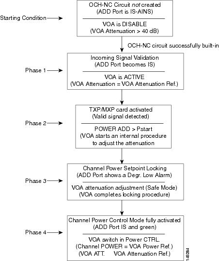
- VOA Startup Phases
- VOA Failure Scenarios
- Scenario A: Optical Power Level of the Incoming Signal Lower Than Minimum Allowed by MSTP Supported Optical Interfaces
- Corrective Action for Scenario A
- Scenario B: Optical Power Level of the Incoming Signal Lower Than Expected
- Condition B1—Delta Power > 6 dB (LOS-P Alarm)
- Condition B2—Delta Power less than 6 dB (OPWR-LowDEGrade Alarm)
- Corrective Actions for Scenario B (Optical Power Level of Incoming Signal Lower than Expected)
- Condition B1 - LOS-P Alarm
- Condition B2 - OPWR-LowDEGrade Alarm
- Scenario C: Optical Drop Power Level Lower Than Expected
- Condition C1—Delta Power > 6 dB Lower than Expected
- Condition C2—Delta Power less than 6 dB Lower than Expected
- Corrective Action for Scenario C (Optical Power Level of Incoming Signal Lower than Expected)
- Scenario C1 - LOS-P Alarm
- Scenario C2 - OPWR-LowDEGrade Alarm
- Counter-Propagating Light Affecting Operation of 32DMX-C and 32DMX-L Cards
- Corrective Action for Software Releases Lower than 9.0
- Controller Card Compatibility
General Troubleshooting
This chapter provides procedures for troubleshooting the most common problems encountered when operating a Cisco ONS 15454 DWDM shelf in ANSI or ETSI platforms. To troubleshoot specific alarms, see Alarm Troubleshooting If you cannot find what you are looking for, contact Cisco Technical Support (1 800 553-2447).
Alarms can occur even in those cards that are not explicitly mentioned in the Alarm sections. When an alarm is raised, refer to its clearing procedure.
NoteUnless otherwise noted, ONS 15454 refers to the ANSI and ETSI versions of the platform.
Note
For dense wavelength division multiplexing (DWDM) network acceptance tests, refer to the Cisco ONS 15454 DWDM Procedure Guide.
This chapter includes the following sections on network problems:
- Loopback Description
- Troubleshooting MXP, TXP, XP, or ADM-10G Circuit Paths With Loopbacks
- Troubleshooting DWDM Circuit Paths With ITU-T G.709 Monitoring
- Using CTC Diagnostics
- Onboard Failure Logging
- Restoring the Database and Default Settings
- PC Connectivity Troubleshooting
- CTC Operation Troubleshooting
- Timing
- Fiber and Cabling
- Power Supply Problems
- Power Up Problems for Node and Cards
- Network Level (Internode) Problems
- Node Level (Intranode) Problems
- Controller Card Compatibility
Loopback Description
Use loopbacks and hairpin circuits to test newly created circuits before running live traffic or to logically locate the source of a network failure. All ONS 15454 SONET and ONS 15454 SDH TXP and MXP cards allow loopbacks and hairpin test circuits. The ADM-10G allows loopbacks, but does not support hairpin circuits. The OPT-AMP-C, OPT-AMP-17C to OPT-BST, OPT-PRE, OPT-BST, OPT-PRE, OSC-CSM, AD-xB-xx.x, and AD-xC-xx.x cards do not support loopbacks and hairpin test circuits.
To create a loopback on an ANSI or SONET port, the port must be in the Out-of-Service and Management, Maintenance (OOS-MA,MT) service state. After you create the loopback, the service state becomes Out-of-Service and Management, Loopback and Maintenance (OOS-MA,LPBK & MT).
To create a loopback on an SDH or ETSI port, the port must be in the Locked, maintenance administrative state and the Locked-Enabled, loopback & maintenance administrative state.
Caution
Facility or terminal loopbacks can be service-affecting. To protect traffic, apply a lockout or Force switch to the target loopback port. Basic directions for these procedures exist in Alarm Troubleshooting chapter. For more information about these operations, refer to the Maintain the Node chapter in the Cisco ONS 15454 DWDM Procedure Guide.
Note
In CTC, a facility loopback is sometimes called facility (line) loopback, and a terminal loopback is sometimes called a terminal (inward) loopback. This is done to indicate the terminating direction of the signal: a facility loopback is sent outward toward the span, whereas a terminal loopback is redirected inward toward its originating port.
Facility Loopbacks
The following sections give general information about facility loopback operations and specific information about ONS 15454 or ONS 15454 SDH card loopback activity.
General Behavior
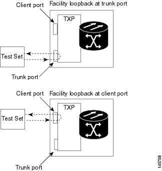
A facility loopback tests the line interface unit (LIU) of a card, the electrical interface assembly (EIA), and related cabling. After applying a facility loopback on a port, use a test set to run traffic over the loopback. A successful facility loopback isolates the LIU, the EIA, or the cabling plant as the potential cause of a network problem.
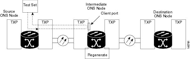
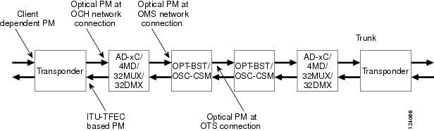
To test a card LIU, connect an optical test set to a trunk or client port and perform a facility loopback. Alternately, use a loopback or hairpin circuit on a card that is farther along the circuit path. For example, Figure 1 shows a facility loopback at a trunk port and at a client port on a TXP card.
Caution
Before performing a facility loopback on a TXP card, be sure that the card contains at least two data communications channel (DCC) paths to the node where the card is installed. A second DCC provides a nonlooped path to log into the node after the loopback is applied, enabling you to remove the facility loopback. Ensuring a second DCC is not necessary if you are directly connected to the node containing the loopback card.
Caution
Ensure that the facility being loopbacked is not being used by the node for line timing. If it is, a timing loop will be created.
Card Behavior
Port loopbacks either terminate or bridge the loopback signal. All MXP and TXP facility loopbacks are terminated as shown in the following table.
When a port terminates a facility loopback signal, the signal only loops back to the originating port and is not transmitted downstream. When a port bridges a loopback signal, the signal loops back to the originating port and is also transmitted downstream.
Note
In the following table, no alarm indication signal (AIS) is injected if the signal is bridged. If the signal is terminated, an applicable AIS is injected downstream.
Table 1 DWDM Card Facility Loopback Behavior Card/Port
Facility Loopback Signal
TXP_MR_10E/TXP_MR_10E_C/TXP_MR_10E_L client ports
Bridged
TXP_MR_10E/TXP_MR_10E_C/TXP_MR_10E_L trunk ports
Terminated
TXP_MR_2.5G/TXPP_MR_2.5G client ports
Terminated
TXP_MR_2.5G/TXPP_MR_2.5G trunk ports
Terminated
MXP_2.5G_10E_C/MXP_2.5G_10E_L client ports
Bridged
MXP_2.5G_10E_C/MXP_2.5G_10E_L trunk ports
Terminated
MXP_MR_10DME client ports
Terminated
MXP_MR_10DME trunk ports
Terminated
MXP_MR_2.5G/MXPP_MR_2.5G client ports
Bridged
MXP_MR_2.5G/MXPP_MR_2.5G trunk ports
Terminated
GE_XP/10GE_XP client ports
Bridged
GE_XP/10GE_XP trunk ports
Terminated
ADM-10G client ports
Bridged
ADM-10G trunk ports
Terminated
40G-MXP-C client ports
Bridged
40G-MXP-C trunk ports
Bridged
The loopback itself is listed in the Conditions window. For example, the window would list the LPBKFACILITY condition for a tested port. (The Alarms window would show the AS-MT condition which means that alarms are suppressed on the facility during loopback unless the default is set to alarm for loopback while in AS-MT.)
With a client-side SONET or ANSI facility loopback, the client port service state is OOS-MA,LPBK & MT. However, any remaining client and trunk ports can be in any other service state. For SONET or ANSI cards in a trunk-side facility loopback, the trunk port service state is OOS-MA,LPBK & MT and the remaining client and trunk ports can be in any other service state.
With a client-side SDH or ESTI facility loopback, the client port is in the Locked-enabled,maintenance & loopback service state. However, the remaining client and trunk ports can be in any other service state. For MXP and TXP cards in a SDH or ETSI trunk-side facility loopback, the trunk port is in the Locked-enabled,maintenance & loopback service state and the remaining client and trunk ports can be in any other service state.
When you apply a facility loopback on the GE_XP, 10GE_XP, GE_XPE, and 10GE_XPE cards, the ifInDiscard counters increment continuously.
Terminal Loopbacks
The following sections give general information about terminal loopback operations and specific information about ONS 15454 card loopback activity.
General Behavior
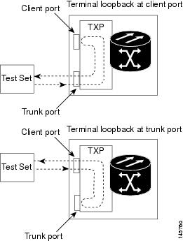
A terminal loopback tests a circuit path as it passes through a TXP, MXP, or ADM-10G card and loops back. For example, as shown in Figure 1, there are two types of terminal loopbacks shown for a TXP card.
The first is a terminal loopback at the client port. In this situation, the test set traffic comes in through the TXP trunk port, travels through the card, and turns around because of the terminal loopback in effect on the card just before it reaches the LIU of the client port. The signal is then sent back through the card to the trunk port and back to the test set.
The second is a terminal loopback at the trunk port. In this situation, the test set traffic comes in through the TXP client port, travels through the card, and turns around because of the terminal loopback in effect on the card just before it reaches the LIU of the trunk port. The signal is then sent back through the card to the client port and back to the test set.
This test verifies that the terminal circuit paths are valid, but does not test the LIU on the TXP card.
Card Behavior
ONS 15454 and ONS 15454 SDH terminal port loopbacks can either terminate or bridge the signal. TXP terminal loopbacks are terminated as shown in the following table. During terminal loopbacks, if a port terminates a terminal loopback signal, the signal only loops back to the originating port and is not transmitted downstream. If the port bridges a loopback signal, the signal loops back to the originating port and is also transmitted downstream. Client card terminal loopback bridging and terminating behaviors are listed in the following table.
Note
AIS signal is not injected if the signal is bridged. If the signal is terminated, an applicable AIS is injected downstream.
Table 2 DWDM Card Terminal Loopback Behavior Card/Port
Terminal Loopback Signal
TXP_MR_10E/TXP_MR_10E_C/TXP_MR_10E_L client ports
Bridged
TXP_MR_10E/TXP_MR_10E_C/TXP_MR_10E_L trunk ports
Bridged
TXP_MR_2.5G/TXPP_MR_2.5G client ports
Bridged
TXP_MR_2.5G/TXPP_MR_2.5G trunk ports
Bridged
MXP_2.5G_10E_C/MXP_2.5G_10E_L client ports
Bridged
MXP_2.5G_10E_C/MXP_2.5G_10E_L trunk ports
Bridged
MXP_MR_10DME client ports
Bridged
MXP_MR_10DME trunk ports
Bridged
MXP_MR_2.5G/MXPP_MR_2.5G client ports
Bridged
MXP_MR_2.5G/MXPP_MR_2.5G trunk ports
Bridged
GE_XP/10GE_XP client ports
Bridged
GE_XP/10GE_XP trunk ports
Bridged
ADM-10G client ports
Bridged
ADM-10G trunk ports
Bridged
40G-MXP-C client ports
Bridged
40G-MXP-C trunk ports
Bridged
Important notes about loopback on MXP and TXP trunk and client ports:
- For SONET or ANSI TXP and TXPP cards with a client-side terminal loopback, the client port is in the OOS-MA,LPBK & MT service state and trunk port must be in IS-NR service state.
- For SONET or ANSI MXP and MXPP cards with a client-side terminal loopback, the client port is in the OOS-MA,LPBK & MT service state and the remaining client and trunk ports can be in any service state.
- For ADM-10G cards with Client Terminal Loopback on a SONET Client port, AIS-P is sent forward on client for the circuits on that port.
- For ADM-10G cards with a Terminal Loopback on a GE Client port, the client port is squelched.
- In SONET or ANSI MXP or TXP trunk-side terminal loopbacks, the trunk port is in the OOS-MA,LPBK & MT service state and the client ports must be in IS-NR service state for complete loopback functionality. A terminal loopback affects all client ports because it is performed on the aggregate signal.
- For ADM-10G cards with a Facility Loopback on the Trunk port, AIS-P is sent forward on all the SONET client ports.
- For ADM-10G cards with a Facility Loopback on the Trunk port, all the GE client ports is squelched
- For ADM-10G Terminal Loopback on the Trunk port, the signal is anyway sent downstream (drop and continue).
- For SDH or ETSI TXP and TXPP client-side facility loopbacks, the client port is in the Locked-enabled,maintenance & loopback service state and the trunk port must be in Unlocked-enabled service state.
- For SDH or ETSI MXP and MXPP cards with a client-side terminal loopback, the client port is in the Locked-enabled,maintenance & loopback service state and remaining client and trunk ports can be in any service state.
- In SDH and ETSI MXP or TXP trunk-side terminal loopbacks, the trunk port is in the Locked-enabled,maintenance & loopback service state and the client ports must be in Unlocked-enabled service state for complete loopback functionality. A facility loopback affects all client ports because it is performed on the aggregate signal.
The loopback itself is listed in the Conditions window. For example, the window would list the LPBKTERMINAL condition or LPBKFACILITY condition for a tested port. (The Alarms window would show the AS-MT condition, which indicates that all alarms are suppressed on the port during loopback testing unless the default is set to alarm for loopback while in AS-MT.)
Troubleshooting MXP, TXP, XP, or ADM-10G Circuit Paths With Loopbacks
Facility loopbacks and terminal loopbacks are often used together to test the circuit path through the network or to logically isolate a fault. Performing a loopback test at each point along the circuit path systematically isolates possible points of failure. MXP, TXP, XP, or ADM-10G card loopback tests differ from other testing in that loopback testing does not require circuit creation. MXP, TXP, and XP client ports are statically mapped to the trunk ports so no signal needs to traverse the cross-connect card (in a circuit) to test the loopback.
You can use these procedures on transponder cards (TXP, TXPP, ADM-10G), muxponder, or xponder cards (MXP, MXPP, XP, ADM-10G) cards. The example in this section tests an MXP or TXP circuit on a three-node bidirectional line switched ring (BLSR) or multiplex section-shared protection ring (MS-SPRing). Using a series of facility loopbacks and terminal loopbacks, the example scenario traces the circuit path, tests the possible failure points, and eliminates them. The logical progression contains six network test procedures:
Note
MXP, TXP, XP, or ADM-10G card client ports do not appear when you click the Maintenance > Loopback tab unless they have been provisioned. Do this in the card view by clicking the Provisioning > Pluggable Port Modules tab. For information about provisioning client ports, refer to the Provision Transponder and Muxponder Cards chapter in the Cisco ONS 15454 DWDM Procedure Guide.
Note
The test sequence for your circuits will differ according to the type of circuit and network topology.
- A facility loopback on the source-node MXP, TXP, XP, or ADM-10G port
- A terminal loopback on the source-node MXP, TXP, XP, or ADM-10G port
- A facility loopback on the intermediate-node MXP, TXP, XP, or ADM-10G port
- A terminal loopback on the intermediate-node MXP, TXP, XP, or ADM-10G port
- A facility loopback on the destination-node MXP, TXP, XP, or ADM-10G port
- A terminal loopback on the destination-node MXP, TXP, XP, or ADM-10G port
Note
Facility and terminal loopback tests require on-site personnel.
- Perform a Facility Loopback on a Source-Node MXP or TXP Port
- Perform a Terminal Loopback on a Source-Node MXP, TXP, XP, or ADM-10G Port
- Create a Facility Loopback on an Intermediate-Node MXP or TXP Port
- Create a Terminal Loopback on Intermediate-Node MXP or TXP Ports
- Perform a Facility Loopback on a Destination-Node MXP, TXP, XP, or ADM-10G Port
- Perform a Terminal Loopback on a Destination-Node MXP, TXP, XP, or ADM-10G Port
Perform a Facility Loopback on a Source-Node MXP or TXP Port
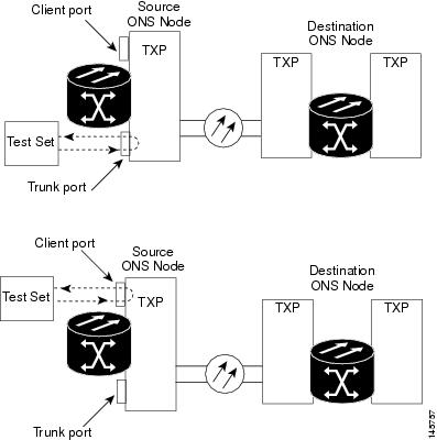
This facility loopback test is performed on the node source port in the network circuit. In the testing situation used in this example, the source muxponder, transponder, xponder, or ADM-10G port under test is located in the source node. Facility loopback can be performed at the trunk port or at a client port. Completing a successful facility loopback on this port isolates the source MXP, TXP, XP, or ADM-10G port as a possible failure point. Figure 1 shows the facility loopback examples on source ONS node TXP ports (client and trunk).
Caution
Performing a loopback on an in-service circuit is service-affecting.
Note
Facility loopbacks require on-site personnel.
Complete the Create the Facility Loopback on the Source-Node MXP, TXP, XP or ADM-10G Port.
- Create the Facility Loopback on the Source-Node MXP, TXP, XP or ADM-10G Port
- Test and Clear the MXP, TXP, XP or ADM-10G Facility Loopback Circuit
- Test the MXP, TXP, XP or ADM-10G Card
Create the Facility Loopback on the Source-Node MXP, TXP, XP or ADM-10G Port
Procedure
Step 1 Connect an optical test set to the port you are testing.
Note For specific procedures to connect, set up, and use the test set equipment, consult the manufacturer.
Use appropriate cabling to attach the transmit (Tx) and receive (Rx) terminals of the optical test set to the port you are testing. The Tx and Rx terminals connect to the same port.
Step 2 Adjust the test set accordingly. (Refer to manufacturer instructions for test set use.) Step 3 In node view (single-shelf mode) or shelf view (multishelf mode), double-click the card to display the card view. Step 4 Click the Maintenance > Loopback tabs. Step 5 Choose OOS,MT (or locked,maintenance) from the Admin State column for the port being tested. If this is a multiport card, select the appropriate row for the desired port. Step 6 Choose Facility (Line) from the Loopback Type column for the port being tested. If this is a multiport card, select the appropriate row for the desired port. Step 7 Click Apply. Step 8 Click Yes in the confirmation dialog box.
Note It is normal for the LPBKFACILITY (ESCON), LPBKFACILITY (FC), LPBKFACILITY (GE), LPBKFACILITY (ISC), or the LPBKFACILITY (TRUNK) to appear during loopback setup. The condition clears when you remove the loopback.
Step 9 Complete the Test and Clear the MXP, TXP, XP or ADM-10G Facility Loopback Circuit.
Test and Clear the MXP, TXP, XP or ADM-10G Facility Loopback Circuit
Procedure
Step 1 If the test set is not already sending traffic, send test traffic on the loopback circuit. Step 2 Examine the traffic received by the test set. Look for errors or any other signal information that the test set is capable of indicating. Step 3 If the test set indicates no errors, no further testing is necessary with the facility loopback. Clear the facility loopback:
- Click the Maintenance > Loopback tabs.
- Choose None from the Loopback Type column for the port being tested.
- Choose the appropriate state to place the port in service, out of service and disabled, out of service for maintenance, or automatically in service from the Admin State column for the port being tested.
- Click Apply.
- Click Yes in the confirmation dialog box.
- Complete the Perform a Terminal Loopback on a Source-Node MXP, TXP, XP, or ADM-10G Port.
Step 4 If the test set indicates errors, complete the Test the MXP, TXP, XP or ADM-10G Card.
Test the MXP, TXP, XP or ADM-10G Card
Procedure
Step 1 Complete the Physically Replace a Card for the suspected bad card and replace it with a known-good one.
Warning High-performance devices on this card can get hot during operation. To remove the card, hold it by the faceplate and bottom edge. Allow the card to cool before touching any other part of it or before placing it in an antistatic bag. Statement 201
Caution Removing a card that currently carries traffic on one or more ports can cause a traffic hit. To avoid this, perform an external switch if a switch has not already occurred. Refer to the procedures in the Protection Switching, Lock Initiation, and Clearing. For more information, refer to the Maintain the Node chapter in the Cisco ONS 15454 DWDM Procedure Guide.
Step 2 Resend test traffic on the loopback circuit with a known-good card installed. Step 3 If the test set indicates no errors, the problem was probably the defective card. Return the defective card to Cisco through the Return Materials Authorization (RMA) process. Contact Cisco Technical Support 1 800 553 2447. Step 4 Clear the facility loopback:
- Click the Maintenance > Loopback tabs.
- Choose None from the Loopback Type column for the port being tested.
- Choose the appropriate state to place the port in service, out of service and disabled, out of service for maintenance, or automatically in service from the Admin State column for the port being tested.
- Click Apply.
- Click Yes in the confirmation dialog box.
Step 5 Complete the Perform a Terminal Loopback on a Source-Node MXP, TXP, XP, or ADM-10G Port.
Perform a Terminal Loopback on a Source-Node MXP, TXP, XP, or ADM-10G Port
The terminal loopback test is performed on the node source MXP, TXP, XP, or ADM-10G port. For the circuit in this example, it is the source TXP trunk port or a client port in the source node. Completing a successful terminal loopback to a node source port verifies that the circuit is through the source port. Figure 1 shows an example of a terminal loopback on a source TXP port and a client TXP port.
Caution
Performing a loopback on an in-service circuit is service-affecting.
Note
Terminal loopbacks require on-site personnel.
Complete the Create the Terminal Loopback on a Source-Node MXP, TXP, XP, or ADM-10G Port.
- Create the Terminal Loopback on a Source-Node MXP, TXP, XP, or ADM-10G Port
- Test and Clear the MXP, TXP, XP, or ADM-10G Port Terminal Loopback Circuit
- Test the MXP, TXP, XP, or ADM-10G Card
Create the Terminal Loopback on a Source-Node MXP, TXP, XP, or ADM-10G Port
Procedure
Step 1 Connect an optical test set to the port you are testing:
Note For specific procedures to connect, set up, and use the test set equipment, consult the manufacturer.
- If you just completed the Perform a Facility Loopback on a Source-Node MXP or TXP Port, leave the optical test set hooked up to the MXP, TXP, XP, or ADM-10G port in the source node.
- If you are starting the current procedure without the optical test set hooked up to the source port, use appropriate cabling to attach the Tx and Rx terminals of the optical test set to the port you are testing. Both Tx and Rx connect to the same port.
Step 2 Adjust the test set accordingly. (Refer to manufacturer instructions for test set use.) Step 3 In node view (single-shelf mode) or shelf view (multishelf mode), double-click the card that requires the loopback. Step 4 Click the Maintenance > Loopback tabs. Step 5 Select OOS,MT (or locked,maintenance) from the Admin State column. If this is a multiport card, select the row appropriate for the desired port. Step 6 Select Terminal (Inward) from the Loopback Type column. If this is a multiport card, select the row appropriate for the desired port. Step 7 Click Apply. Step 8 Click Yes in the confirmation dialog box. Step 9 Complete the Test and Clear the MXP, TXP, XP, or ADM-10G Port Terminal Loopback Circuit.
Test and Clear the MXP, TXP, XP, or ADM-10G Port Terminal Loopback Circuit
Procedure
Step 1 If the test set is not already sending traffic, send test traffic on the loopback circuit. Step 2 Examine the test traffic being received by the test set. Look for errors or any other signal information that the test set is capable of indicating. Step 3 If the test set indicates no errors, no further testing is necessary on the loopback circuit. Clear the terminal loopback state on the port:
- Double-click the card in the source node with the terminal loopback.
- Click the Maintenance > Loopback tabs.
- Select None from the Loopback Type column for the port being tested.
- Choose the appropriate state to place the port in service, out of service and disabled, out of service for maintenance, or automatically in service from the Admin State column for the port being tested.
- Click Apply.
- Click Yes in the confirmation dialog box.
- Complete the Create a Facility Loopback on an Intermediate-Node MXP or TXP Port.
Step 4 If the test set indicates errors, complete the Test the MXP, TXP, XP, or ADM-10G Card.
Test the MXP, TXP, XP, or ADM-10G Card
Procedure
Step 1 Complete the Physically Replace a Card for the suspected bad card and replace it with a known-good one.
Warning High-performance devices on this card can get hot during operation. To remove the card, hold it by the faceplate and bottom edge. Allow the card to cool before touching any other part of it or before placing it in an antistatic bag. Statement 201
Caution Removing a card that currently carries traffic on one or more ports can cause a traffic hit. To avoid this, perform an external switch if a switch has not already occurred. Refer to the procedures in the Protection Switching, Lock Initiation, and Clearing. For more information, refer to the Maintain the Node chapter in the Cisco ONS 15454 DWDM Procedure Guide.
Step 2 Resend test traffic on the loopback circuit with a known-good card. Step 3 If the test set indicates no errors, the problem was probably the defective card. Return the defective card to Cisco through the RMA process. Contact Cisco Technical Support 1 800 553 2447. Step 4 Clear the terminal loopback on the port before testing the next segment of the network circuit path:
- Double-click the card in the source node with the terminal loopback.
- Click the Maintenance > Loopback tabs.
- Select None from the Loopback Type column for the port being tested.
- Choose the appropriate state to place the port in service, out of service and disabled, out of service for maintenance, or automatically in service from the Admin State column for the port being tested.
- Click Apply.
- Click Yes in the confirmation dialog box.
Step 5 Complete the Create a Facility Loopback on an Intermediate-Node MXP or TXP Port.
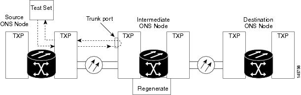
Create a Facility Loopback on an Intermediate-Node MXP or TXP Port
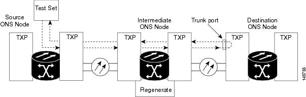
Performing the facility loopback test on an intermediate port isolates whether this node is causing circuit failure. In the situation shown in Figure 1, the test is being performed on an intermediate MXP or TXP port.
Caution
Performing a loopback on an in-service circuit is service-affecting.
Note
Facility loopbacks require on-site personnel.
Complete the Create a Facility Loopback on an Intermediate-Node MXP or TXP Port.
- Create a Facility Loopback on an Intermediate-Node MXP or TXP Port
- Test and Clear the MXP or TXP Port Facility Loopback Circuit
- Test the MXP or TXP Card
Create a Facility Loopback on an Intermediate-Node MXP or TXP Port
Procedure
Step 1 Connect an optical test set to the port you are testing:
Note For specific procedures to connect, set up, and use the test set equipment, consult the manufacturer.
- If you just completed the Perform a Terminal Loopback on a Source-Node MXP, TXP, XP, or ADM-10G Port, leave the optical test set hooked up to the source-node port.
- If you are starting the current procedure without the optical test set hooked up to the source port port, use appropriate cabling to attach the Tx and Rx terminals of the optical test set to the port you are testing. Both Tx and Rx connect to the same port.
Step 2 Adjust the test set accordingly. (Refer to manufacturer instructions for test set use.) Step 3 In node view (single-shelf mode) or shelf view (multishelf mode), double-click the intermediate-node card that requires the loopback. Step 4 Click the Maintenance > Loopback tabs. Step 5 Select OOS,MT (or locked,maintenance) from the Admin State column. If this is a multiport card, select the row appropriate for the desired port. Step 6 Select Facility (Line) from the Loopback Type column. If this is a multiport card, select the row appropriate for the desired port. Step 7 Click Apply. Step 8 Click Yes in the confirmation dialog box. Step 9 Complete the Test and Clear the MXP or TXP Port Facility Loopback Circuit.
Test and Clear the MXP or TXP Port Facility Loopback Circuit
Procedure
Step 1 If the test set is not already sending traffic, send test traffic on the loopback circuit. Step 2 Examine the traffic received by the test set. Look for errors or any other signal information that the test set is capable of indicating. Step 3 If the test set indicates no errors, no further testing is necessary with the facility loopback. Clear the facility loopback from the port:
- Click the Maintenance > Loopback tabs.
- Choose None from the Loopback Type column for the port being tested.
- Choose the appropriate state to place the port in service, out of service and disabled, out of service for maintenance, or automatically in service from the Admin State column for the port being tested.
- Click Apply.
- Click Yes in the confirmation dialog box.
- Complete the Create a Terminal Loopback on Intermediate-Node MXP or TXP Ports.
Step 4 If the test set indicates errors, complete the Test the MXP or TXP Card.
Test the MXP or TXP Card
Procedure
Step 1 Complete the Physically Replace a Card for the suspected bad card and replace it with a known-good one.
Warning High-performance devices on this card can get hot during operation. To remove the card, hold it by the faceplate and bottom edge. Allow the card to cool before touching any other part of it or before placing it in an antistatic bag. Statement 201
Caution Removing a card that currently carries traffic on one or more ports can cause a traffic hit. To avoid this, perform an external switch if a switch has not already occurred. Refer to the procedures in the Protection Switching, Lock Initiation, and Clearing. For more information, refer to the Maintain the Node chapter in the Cisco ONS 15454 DWDM Procedure Guide.
Step 2 Resend test traffic on the loopback circuit with a known-good card installed. Step 3 If the test set indicates no errors, the problem was probably the defective card. Return the defective card to Cisco through the RMA process. Contact Cisco Technical Support 1 800 553 2447. Step 4 Clear the facility loopback from the port:
- Click the Maintenance > Loopback tabs.
- Choose None from the Loopback Type column for the port being tested.
- Choose the appropriate state to place the port in service, out of service and disabled, out of service for maintenance, or automatically in service from the Admin State column for the port being tested.
- Click Apply.
- Click Yes in the confirmation dialog box.
Step 5 Complete the Create a Terminal Loopback on Intermediate-Node MXP or TXP Ports.
Create a Terminal Loopback on Intermediate-Node MXP or TXP Ports
In the next troubleshooting test, you perform a terminal loopback on the intermediate-node port to isolate whether the intermediate client or trunk port is causing circuit trouble. In the example situation in Figure 1, the terminal loopback is performed on an intermediate MXP or TXP port in the circuit. If you successfully complete a terminal loopback on the node, this node is excluded from possible sources of circuit trouble.
Caution
Performing a loopback on an in-service circuit is service-affecting.
Note
Terminal loopbacks require on-site personnel.
Complete the Create a Terminal Loopback on Intermediate-Node MXP or TXP Ports.
- Create a Terminal Loopback on Intermediate-Node MXP or TXP Ports
- Test and Clear the MXP or TXP Terminal Loopback Circuit
- Test the MXP or TXP Card
Create a Terminal Loopback on Intermediate-Node MXP or TXP Ports
Procedure
Step 1 Connect an optical test set to the port you are testing:
Note For specific procedures to connect, set up, and use the test set equipment, consult the manufacturer.
- If you just completed the Create a Facility Loopback on an Intermediate-Node MXP or TXP Port, leave the optical test set hooked up to the source-node port.
- If you are starting the current procedure without the optical test set hooked up to the source port, use appropriate cabling to attach the Tx and Rx terminals of the optical test set to the port you are testing. Both Tx and Rx connect to the same port.
Step 2 Adjust the test set accordingly. (Refer to manufacturer instructions for test set use.) Step 3 Create the terminal loopback on the destination port being tested:
Step 4 Complete the Test and Clear the MXP or TXP Terminal Loopback Circuit.
Test and Clear the MXP or TXP Terminal Loopback Circuit
Procedure
Step 1 If the test set is not already sending traffic, send test traffic on the loopback circuit. Step 2 Examine the test traffic being received by the test set. Look for errors or any other signal information that the test set is capable of indicating. Step 3 If the test set indicates no errors, no further testing is necessary on the loopback circuit. Clear the terminal loopback from the port:
- Double-click the intermediate-node card with the terminal loopback to display the card view.
- Click the Maintenance > Loopback tabs.
- Select None from the Loopback Type column for the port being tested.
- Choose the appropriate state to place the port in service, out of service and disabled, out of service for maintenance, or automatically in service from the Admin State column for the port being tested.
- Click Apply.
- Click Yes in the confirmation dialog box.
- Complete the Perform a Facility Loopback on a Destination-Node MXP, TXP, XP, or ADM-10G Port.
Step 4 If the test set indicates errors, complete the Test the MXP or TXP Card.
Test the MXP or TXP Card
Procedure
Step 1 Complete the Physically Replace a Card for the suspected bad card and replace it with a known-good one.
Warning High-performance devices on this card can get hot during operation. To remove the card, hold it by the faceplate and bottom edge. Allow the card to cool before touching any other part of it or before placing it in an antistatic bag. Statement 201
Caution Removing a card that currently carries traffic on one or more ports can cause a traffic hit. To avoid this, perform an external switch if a switch has not already occurred. Refer to the procedures in the Protection Switching, Lock Initiation, and Clearing. For more information, refer to the Maintain the Node chapter in the Cisco ONS 15454 DWDM Procedure Guide.
Step 2 Resend test traffic on the loopback circuit with a known-good card. Step 3 If the test set indicates no errors, the problem was probably the defective card. Return the defective card to Cisco through the RMA process. Contact Cisco Technical Support 1 800 553 2447. Step 4 Clear the terminal loopback on the port:
- Double-click the source-node card with the terminal loopback.
- Click the Maintenance > Loopback tabs.
- Select None from the Loopback Type column for the port being tested.
- Choose the appropriate state to place the port in service, out of service and disabled, out of service for maintenance, or automatically in service from the Admin State column for the port being tested.
- Click Apply.
- Click Yes in the confirmation dialog box.
Step 5 Complete the Perform a Facility Loopback on a Destination-Node MXP, TXP, XP, or ADM-10G Port.
Perform a Facility Loopback on a Destination-Node MXP, TXP, XP, or ADM-10G Port
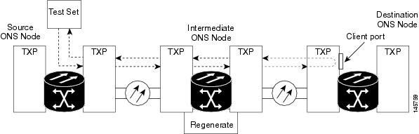
You perform a facility loopback test at the destination port to determine whether this local port is the source of circuit trouble. The example in Figure 1 shows a facility loopback being performed on a TXP client or trunk port at a destination node.
Caution
Performing a loopback on an in-service circuit is service-affecting.
Note
Facility loopbacks require on-site personnel.
Complete the Create the Facility Loopback on a Destination-Node MXP, TXP, XP, or ADM-10G Port.
- Create the Facility Loopback on a Destination-Node MXP, TXP, XP, or ADM-10G Port
- Test and Clear the MXP, TXP, XP, or ADM-10G Facility Loopback Circuit
- Test the MXP, TXP, XP, or ADM-10G Card
Create the Facility Loopback on a Destination-Node MXP, TXP, XP, or ADM-10G Port
Procedure
Step 1 Connect an optical test set to the port you are testing:
Note For specific procedures to connect, set up, and use the test set equipment, consult the manufacturer.
- If you just completed the Create a Terminal Loopback on Intermediate-Node MXP or TXP Ports, leave the optical test set hooked up to the source-node port.
- If you are starting the current procedure without the optical test set hooked up to the source port, use appropriate cabling to attach the Tx and Rx terminals of the optical test set to the port you are testing. Both Tx and Rx connect to the same port.
Step 2 Adjust the test set accordingly. (Refer to manufacturer instructions for test set use.) Step 3 Create the facility loopback on the destination port being tested:
Step 4 Complete the Test and Clear the MXP, TXP, XP, or ADM-10G Facility Loopback Circuit.
Test and Clear the MXP, TXP, XP, or ADM-10G Facility Loopback Circuit
Procedure
Step 1 If the test set is not already sending traffic, send test traffic on the loopback circuit. Step 2 Examine the traffic received by the test set. Look for errors or any other signal information that the test set is capable of indicating. Step 3 If the test set indicates no errors, no further testing is necessary with the facility loopback. Clear the facility loopback from the port:
- Click the Maintenance > Loopback tabs.
- Choose None from the Loopback Type column for the port being tested.
- Choose the appropriate state to place the port in service, out of service and disabled, out of service for maintenance, or automatically in service from the Admin State column for the port being tested.
- Click Apply.
- Click Yes in the confirmation dialog box.
- Complete the Perform a Terminal Loopback on a Destination-Node MXP, TXP, XP, or ADM-10G Port.
Step 4 If the test set indicates errors, complete the Test the MXP, TXP, XP, or ADM-10G Card.
Test the MXP, TXP, XP, or ADM-10G Card
Procedure
Step 1 Complete the Physically Replace a Card for the suspected bad card and replace it with a known-good one.
Warning High-performance devices on this card can get hot during operation. To remove the card, hold it by the faceplate and bottom edge. Allow the card to cool before touching any other part of it or before placing it in an antistatic bag. Statement 201
Caution Removing a card that currently carries traffic on one or more ports can cause a traffic hit. To avoid this, perform an external switch if a switch has not already occurred. Refer to the procedures in the Protection Switching, Lock Initiation, and Clearing. For more information, refer to the Maintain the Node chapter in the Cisco ONS 15454 DWDM Procedure Guide.
Step 2 Resend test traffic on the loopback circuit with a known-good card installed. Step 3 If the test set indicates no errors, the problem was probably the defective card. Return the defective card to Cisco through the RMA process. Contact Cisco Technical Support 1 800 553 2447. Step 4 Clear the facility loopback on the port:
- Click the Maintenance > Loopback tabs.
- Choose None from the Loopback Type column for the port being tested.
- Choose the appropriate state to place the port in service, out of service and disabled, out of service for maintenance, or automatically in service from the Admin State column for the port being tested.
- Click Apply.
- Click Yes in the confirmation dialog box.
Step 5 Complete the Perform a Terminal Loopback on a Destination-Node MXP, TXP, XP, or ADM-10G Port.
Perform a Terminal Loopback on a Destination-Node MXP, TXP, XP, or ADM-10G Port
The terminal loopback at the destination-node port is the final local hardware error elimination in the circuit troubleshooting process. If this test is completed successfully, you have verified that the circuit is good up to the destination port. The example in Figure 1 shows a terminal loopback on an destination node TXP port.
Caution
Performing a loopback on an in-service circuit is service-affecting.
Note
Terminal loopbacks require on-site personnel.
Complete the Create the Terminal Loopback on a Destination-Node MXP, TXP, XP, or ADM-10G Port.
- Create the Terminal Loopback on a Destination-Node MXP, TXP, XP, or ADM-10G Port
- Test and Clear the MXP, TXP, XP, or ADM-10G Terminal Loopback Circuit
- Test the MXP, TXP, XP, or ADM-10G Card
Create the Terminal Loopback on a Destination-Node MXP, TXP, XP, or ADM-10G Port
Procedure
Step 1 Connect an optical test set to the port you are testing:
Note For specific procedures to connect, set up, and use the test set equipment, consult the manufacturer.
- If you just completed the Perform a Facility Loopback on a Destination-Node MXP, TXP, XP, or ADM-10G Port, leave the optical test set hooked up to the source port.
- If you are starting the current procedure without the optical test set hooked up to the source port, use appropriate cabling to attach the Tx and Rx terminals of the optical test set to the port you are testing. Both Tx and Rx connect to the same port.
Step 2 Adjust the test set accordingly. (Refer to manufacturer instructions for test set use.)
Note It is normal for the LPBKFACILITY (ESCON), LPBKFACILITY (FC), LPBKFACILITY (GE), LPBKFACILITY (ISC), or the LPBKFACILITY (TRUNK) to appear during loopback setup. The condition clears when you remove the loopback.
Step 3 Create the terminal loopback on the destination port being tested:
Step 4 Complete the Test and Clear the MXP, TXP, XP, or ADM-10G Terminal Loopback Circuit.
Test and Clear the MXP, TXP, XP, or ADM-10G Terminal Loopback Circuit
Procedure
Step 1 If the test set is not already sending traffic, send test traffic on the loopback circuit. Step 2 Examine the test traffic being received by the test set. Look for errors or any other signal information that the test set is capable of indicating. Step 3 If the test set indicates no errors, no further testing is necessary on the loopback circuit. Clear the terminal loopback from the port:
- Double-click the intermediate-node card with the terminal loopback.
- Click the Maintenance > Loopback tabs.
- Select None from the Loopback Type column for the port being tested.
- Choose the appropriate state to place the port in service, out of service and disabled, out of service for maintenance, or automatically in service from the Admin State column for the port being tested.
- Click Apply.
- Click Yes in the confirmation dialog box.
Step 4 If the test set indicates errors, the problem might be a faulty card. Step 5 Complete the Test the MXP, TXP, XP, or ADM-10G Card.
Test the MXP, TXP, XP, or ADM-10G Card
Procedure
Step 1 Complete the Physically Replace a Card for the suspected bad card and replace it with a known-good one.
Warning High-performance devices on this card can get hot during operation. To remove the card, hold it by the faceplate and bottom edge. Allow the card to cool before touching any other part of it or before placing it in an antistatic bag. Statement 201
Caution Removing a card that currently carries traffic on one or more ports can cause a traffic hit. To avoid this, perform an external switch if a switch has not already occurred. Refer to the procedures in the Protection Switching, Lock Initiation, and Clearing. For more information, refer to the Maintain the Node chapter in the Cisco ONS 15454 DWDM Procedure Guide.
Step 2 Resend test traffic on the loopback circuit with a known-good card. Step 3 If the test set indicates no errors the problem was probably the defective card. Return the defective card to Cisco through the RMA process. Contact Cisco Technical Support 1 800 553 2447. Step 4 Clear the terminal loopback on the port:
Troubleshooting DWDM Circuit Paths With ITU-T G.709 Monitoring
This section provides an overview of the optical transport network (OTN) specified in ITU-T G.709,Network Node Interface for the Optical Transport Network , and provides troubleshooting procedures for DWDM circuit paths in the ITU-T G.709 OTN using PM and TCAs.
- ITU-T G.709 Monitoring in Optical Transport Networks
- Optical Channel Layer
- Optical Multiplex Section Layer
- Optical Transmission Section Layer
- Performance Monitoring Counters and Threshold Crossing Alerts
- Forward Error Correction
- Sample Trouble Resolutions
ITU-T G.709 Monitoring in Optical Transport Networks
ITU-T Recommendation G.709 is part of a suite of recommendations covering the full functionality of an OTN. ITU-T G.709 enables single-wavelength SONET transparent optical wavelength-based networks. ITU-T G.709 adds the Operation, Administration, Maintenance, and Provisioning (OAM&P) functionality of SONET/SDH to DWDM optical networks. It adds extra overhead to existing SONET, Ethernet, or asynchronous transfer mode (ATM) bit streams for performance management and improvement.
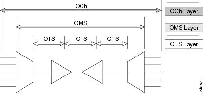
Like traditional SONET networks, ITU-T G.709 optical networks have a layered design (Figure 1). This structure enables localized monitoring that helps you isolate and troubleshoot network problems.
Optical Channel Layer
The optical channel (OCH) layer is the outermost part of the OTN and spans from client to client. The optical channel is built as follows:
A client signal such as SONET, Gigabit Ethernet, IP, ATM, Fibre Channel, or enterprise system connection (ESCON) is mapped to a client payload area and combined with an overhead to create the optical channel payload unit (OPUk).
A second overhead is added to the OPUk unit to create the optical channel data unit (ODUk).
A third overhead including forward error correction (FEC) is added to the ODUk to create the optical channel transport unit (OTUk).
A fourth overhead is added to the OTUk to create the entire OCH layer.
Optical Multiplex Section Layer
The optical multiplex section (OMS) of the OTN allows carriers to identify errors occurring within DWDM network sections. The OMS layer consists of a payload and an overhead (OMS-OH). It supports the ability to monitor multiplexed sections of the network, for example, the span between an optical multiplexer such as the 32MUX-O card and an optical demultiplexer such as the 32DMX-O card.
Optical Transmission Section Layer
The optical transmission section (OTS) layer supports monitoring partial spans of a network multiplexed sections. This layer consists of a payload and an overhead (OTS-OH). It is a transmission span between two elements in an optical network, such as between:
Performance Monitoring Counters and Threshold Crossing Alerts
PM counters and TCAs can be used for identifying trouble and troubleshooting problems in ITU-T G.709 optical transport networks. ITU-T Recommendation M.2401 recommends that the following PM parameters be monitored at the ODUk layer:
- SES (severely errored seconds)A one-second period that contains greater than or equal to 30 percent errored blocks or at least one defect. SES is a subset of the errored second (ES) parameter, which is a one-second period with one or more errored blocks or at least one defect.
- BBE (background block error counter)An errored block not occurring as part of an SES. BBE is a subset of the errored block (EB) parameter, which is a block in which one or more bits are in error.
Different PM count parameters are associated with different read points in a network. Figure 1 illustrates the PM read points that are useful in identifying DWDM circuit points of failure. The Performance Monitoring chapter in the Cisco ONS 15454 DWDM Reference Manual lists all PM parameters and provides block diagrams of signal entry points, exit points, and interconnections between the individual circuit cards. Consult these specifications to determine which PM parameters are associated with the system points you want to monitor or provision with CTC or TL1. The monitoring points might vary according to your configuration.
Note
When LOS, LOS-P, or LOF alarms occur on TXP and MXP trunks, G709/SONET/SDH TCAs are suppressed. For details, see the Alarm and TCA Monitoring and Management chapter in the Cisco ONS 15454 DWDM Procedure Guide.
TCAs are used to monitor performance through the management interface by indicating whether preset thresholds have been crossed, or whether a transmission (such as a laser transmission) is degraded. TCAs are not associated with severity levels. They are usually associated with rate, counter, and percentage parameters that are available at transponder monitoring points. The Performance Monitoring chapter in the Cisco ONS 15454 DWDM Reference Manual contains more information about these alerts.
Select and complete the following procedures according to your network parameters.
- Set Node Default BBE or SES Card Thresholds
- Provision Individual Card BBE or SES Thresholds in CTC
- Provision Card PM Thresholds Using TL1
- Provision Optical TCA Thresholds
Set Node Default BBE or SES Card Thresholds
Provision Individual Card BBE or SES Thresholds in CTC
ProcedureComplete the following procedure to provision BBE or SES PM thresholds in CTC for an individual TXP card.
Provision Card PM Thresholds Using TL1
Procedure
Forward Error Correction
In DWDM spans, FEC reduces the quantities of retiming, reshaping, and regeneration (3R) needed to maintain signal quality. The following two PM parameters are associated with FEC:
- BIT-EC: Bit errors corrected (BIT-EC ) indicates the number of bit errors corrected in the DWDM trunk line during the PM time interval.
- UNC-WORDSThe number of uncorrectable words detected in the DWDM trunk line during the PM time interval.
Complete the following procedure to provision BIT-EC and UNC-WORDS PM parameters for FEC.
Provision Card FEC Thresholds
Procedure
Step 1 In node view (single-shelf mode) or shelf view (multishelf mode), double-click a transponder, muxponder, or xponder card to open the card view. Step 2 Click the Provisioning > OTN > FEC Thresholds tabs. Step 3 In the Bit Errors Corrected field, enter a threshold number, for example 225837. Step 4 In the Uncorrectable Words field, enter a threshold number, for example, 2. Step 5 In the Intervals area, click 15 Min.
Sample Trouble Resolutions
Solution Check the input power on the transponder. It should be within the specified/supported range.Possible Cause There are dirty client connectors on the ADxC-xx.x card transmit port or the demultiplexer (DMX) has crossed the near-end TCA.Possible Cause There are dirty client connectors on the ADxC-xx.x card receive port or the multiplexer (MUX) has crossed the far-end TCA point.Solution Check the input power on the transponder. It should be within the specified/supported range.Possible Cause There is a dirty connector on the ADxB-xx.x card drop port, and it has crossed the near-end TCA point.Possible Cause There is a dirty connector on the ADxB-xx.x card add port and it has crossed the far-end TCA.Using CTC Diagnostics
In Software Release 9.1, CTC provides diagnostics for the following functions:
- Verifying proper card application-specific integrated circuit (ASIC) functionality
- Verifying standby card operation
- Verifying proper card LED operation
- Diagnostic circuit creation
- Customer problem notifications detected by alarms
- Provision of a downloadable, machine-readable diagnostic information file to be used by Cisco Technical Support
Some of these functions, such as ASIC verification and standby card operation, are invisibly monitored in background functions. Change or problem notifications are provided in the Alarms and Conditions windows. Other diagnostic functionsverifying card LED function, creating bidirectional diagnostic circuits, and also downloading diagnostic files for technical supportare available to the user in the node view (single-shelf mode) or shelf view (multishelf mode) Maintenance > Diagnostic tab. The user-operated diagnostic features are described in the following paragraphs.
Card LED Lamp Tests
A card LED lamp test determines whether card-level indication LEDs are operational. This diagnostic test is run as part of the initial ONS 15454 turn-up, during maintenance routines, or any time you question whether an LED is in working order. Maintenance or higher-level users can complete the following tasks to verify LED operation.
Verify Card LED Operation
Procedure
Step 1 In node view (single-shelf mode) or shelf view (multishelf mode), click the Maintenance > Diagnostic tabs. Step 2 Click Lamp Test. Step 3 Watch to make sure all the port LEDs illuminate simultaneously for several seconds, with the following durations: Step 4 Click OK in the Lamp Test Run dialog box.
Retrieve Tech Support Logs Button
When you click the Retrieve Tech Support Logs button in the Diagnostics tab of the Maintenance window, CTC retrieves system data that a Retrieve or higher level user can off-load to a local directory and send to Technical Support for troubleshooting purposes. The diagnostics file is in machine language and is not human-readable, but can be used by Cisco Technical Support for problem analysis. Complete the following procedure to off-load the diagnostics file.
Note
In addition to the machine-readable diagnostics file, the ONS 15454 stores an audit trail of all system events such as user log-ins, remote log-ins, configuration, and changes. This audit trail is considered a record-keeping feature rather than a troubleshooting feature. Information about the feature is located in the Maintain the Node chapter of the Cisco ONS 15454 DWDM Procedure Guide.
Off-Load the Diagnostics File
Procedure
Note
The diagnostics operation is performed at a shelf level. Only single-node-related diagnostic information can be downloaded at a time.
The diagnostic files retrieved by CTC depends on the user privilege levels. Table 1 lists the user privilege levels and the diagnostic retrieval operations they can perform.
Step 1 In the node view, click the Maintenance > Diagnostic tabs. Step 2 Click Retrieve Tech Support Logs in the Controller area. Step 3 In the Select a Filename for the Tech Support Logs Zip Archive dialog box, add the diagnostics file name in the format TechSupportLogs_<node_name>.zip by default. Substitute the last 20 alphanumeric characters of the node name for <node_name>. Navigate to the directory (local or network) where you want to save the file. A message appears asking you if you want to overwrite any existing disgnostics file in the selected directory.
Step 4 Click Save. CTC performs the diagnostic tasks and writes the diagnostic files in a folder named TechSupportLogs_<node_name> under the location selected in Step 3. After all the diagnostic files are written to the TechSupportLogs_<node_name> folder, CTC archives the retrieved diagnostic files as TechSupportLogs_<node_name>.zip. CTC deletes the TechSupportLogs_<node_name> folder after the archiving process is successfully completed. CTC retains this folder if the archiving process fails. The retrieved diagnostic files can be accessed in the TechSupportLogs_<node_name> folder.
A progress bar indicates the percentage of the file that is being saved. The Save Tech Support Logs Completed dialog box appears when the file is saved. CTC logs any error during the retrieval and archiving of diagnostics file to the CTC Alerts Log.
Table 2 lists the diagnostic files retrieved by CTC.
Table 4 List of Diagnostic Files Diagnostic File
Diagnostic File Content
AlarmTableLog.html
Alarm Table export
HistoryTableLog.html
Alarm Table export
ConditionsTableLog.html
Conditions Table export
InventoryTableLog.html
Inventory Table export
AuditTableLog.html
Audit Table export
CTCDumpDiagLog.txt
Audit Table export
NodeDiagnostics.bin
NodeDiagnostics.gz
OBFLDiagnostics.bin
OBFLDiagnostics.bin
NodeDatabaseBackup.bin
Database backup
TechSupportLogs_<node_name>.zip
Zip archive of all the diagnostics file
Step 5 Click OK.
Data Communications Network Tool
CTC contains a data communications network (DCN) tool that assists with network troubleshooting for Open Shortest Path First (OSPF) networks. It executes an internal dump command to retrieve information about all nodes accessible from the entry point.
The dump, which provides the same information as a dump executed by special networking commands, is available at the network view in the Maintenance > Diagnostic tab. You can select the access point node in the Select Node drop-down list. To create the dump, click Retrieve. (To clear the dump, click Clear.)
The contents of the dump file can be saved or printed and furnished to Cisco Technical Support for use in OSPF network support.
Onboard Failure Logging
Onboard Failure Logging (OBFL) records events that occur during the card operation. In the event of card failure, the stored log can assist in determining root cause of failure. The OBFL data is stored in two different formats:
The OBFL feature is supported on the following cards:
Note
To determine if OBFL is supported on the OPT-BST and OPT-PRE cards running in your system, contact the Cisco Technical Assistance Center (TAC).
Note
The stored logs can be retrieved only by the Cisco support team to diagnose the root cause of the card failure.
Run Time Log for IO Cards
Run time log traces events and critical information such as alarms raised and cleared, power variations and so on, during the working of the card. The stored logs help identify the cause of failure.
For legacy cards (OPT-BST and OPT-PRE), the run time logs are automatically stored in RAM and are deleted when the card is hard reset. To store the logs in the permanent memory, the user should take the snapshot of logs as explained in the Snapshot Logging in CTC section. For new cards (40-SMR1-C and 40-SMR2-C), the run time logs are automatically written to the flash memory and are not deleted even after reset or hard reboot of the card.
The following table lists a few run time logs captured for a specific event:
Table 5 Run Time Logging—Events and Logs Event
Log
When the change in Rx and Tx optical power in the active stage is greater than the threshold value, the unit stores the input and output power every second. The difference between the two adjacent input power readings or two adjacent output power readings is greater than 1 db, and this event occurs more than 10 times in 30 seconds
Target power not reached (0.5 dB or more difference from set point)
Fiber Temperature Alarm
Laser Temperature Alarm
Case Temperature Alarm
Communication error with TCC
Snapshot Log for IO Cards
Snapshot log captures the board's information at any given time. In CTC, the user has an option to take a snapshot of the current status of the card. When the snapshot is taken, a log file will be created that contains the information from the card. In addition to the information stored in the run time logs, the snapshot log contains details like card parameters, alarm history, and so on. For legacy and new cards, the snapshot logs are written to the flash memory. When EQPT-FAIL alarm is detected on the card, a snapshot of the log will be automatically taken by the card. In the event of card failure due to other reasons, the users must take the snapshot of logs before swapping the card. Refer to the Snapshot Logging in CTC section.
Snapshot Logging in CTC
ProcedureThe users can take the snapshot of logs in the event of card failure, before replacing the card. This section explains the steps to take snapshot of logs in CTC:
Step 1 Login to CTC. Step 2 In node view (single-shelf mode) or shelf view (multishelf mode), double-click the card to open it in the card view. Step 3 Click the Maintenance > OBFL tabs. Step 4 Click Start Onboard Failure logging. The OBFL Info dialog box is displayed. Step 5 Click Yes to continue. The Onboard failure logging feature is launched. Step 6 Click OK. The snapshot log will be written to the flash memory.
Restoring the Database and Default Settings
This section contains troubleshooting for node operation errors that require restoration of software data or the default node setup.
PC Connectivity Troubleshooting
This section contains information about system minimum requirements, supported platforms, browsers, and Java Runtime Environments (JREs) for Software R9.2 , and troubleshooting procedures for PC and network connectivity to the ONS 15454. Table 1-6 lists the requirements for PCs and UNIX workstations. In addition to the JRE, the Java plug-in is also included on the ONS 15454 software CD.
Table 6 Computer Requirements for CTC Area
Requirements
Notes
Processor (PC only)
Pentium 4 processor or equivalent
A faster CPU is recommended if your workstation runs multiple applications or if CTC manages a network with a large number of nodes and circuits.
RAM
1 GB RAM or more
A minimum of 1 GB is recommended if your workstation runs multiple applications or if CTC manages a network with a large number of nodes and circuits.
Hard drive
20 GB hard drive with 250 MB of free space required
CTC application files are downloaded from the TCC2/TCC2P/TCC3/TNC/TSC to your computer. These files occupy around 100MB (250MB to be safer) or more space depending on the number of versions in the network.
Operating System
- PC: Windows 2000, Windows XP, Windows Vista, Windows XP, Windows 7, Windows Server 2003 and 2008.
- Workstation: Solaris versions 9 or 10 on an UltraSPARC-III or faster processor, with a minimum of 1 GB RAM and a minimum of 250 MB of available hard drive space.
- Apple Mac OS X. CTC needs to be installed using the CacheInstaller available on CCO or the ONS CD.
Use the latest patch/Service Pack released by the OS vendor. Check with the vendor for the latest patch/Service Pack.
Java Runtime Environment
JRE 1.6 is installed by the CTC Installation Wizard included on the ONS 15454, 15454-M2, or 15454-M6 software CD. JRE 1.6 provides enhancements to CTC performance, especially for large networks with numerous circuits.
We recommend that you use JRE 1.6 for networks with Software R9.2 nodes. If CTC must be launched directly from nodes running software R7.0 or R7.2, We recommend JRE 1.4.2 or JRE 5.0. If CTC must be launched directly from nodes running software R5.0 or R6.0, we recommend JRE 1.4.2. If CTC must be launched directly from nodes running software earlier than R5.0, we recommend JRE 1.3.1_02.
Web browser
For the PC, use JRE 1.6 with any supported web browser.
The supported browser can be downloaded from the Web.
Cable
—
- Unable to Verify the IP Configuration of Your PC
- Browser Login Does Not Launch Java
- Unable to Verify the NIC Connection on Your PC
- Verify PC Connection to the ONS 15454 (ping)
- The IP Address of the Node is Unknown
Unable to Verify the IP Configuration of Your PC
Problem When connecting your PC to the ONS 15454, you are unable to successfully ping the IP address of your PC to verify the IP configuration.Solution Verify that the IP address used to ping the PC matches the IP address displayed when in the Windows IP Configuration information retrieved from the system. See the Verify the IP Configuration of Your PC.Solution Verify the IP configuration of your PC. Complete the Verify the IP Configuration of Your PC. If this procedure is unsuccessful, contact your network administrator for instructions to correct the IP configuration of your PC.Verify the IP Configuration of Your PC
Procedure
Step 1 Open a DOS command window by selecting Start > Run from the Start menu. Step 2 In the Open field, type command and then click OK. The DOS command window appears. Step 3 At the prompt in the DOS window, type ipconfig and press the Enter key. The Windows IP configuration information appears, including the IP address, the subnet mask, and the default gateway.
Note The winipcfg command only returns the information above if you are on a network.
Step 4 At the prompt in the DOS window, type ping followed by the IP address shown in the Windows IP configuration information previously displayed. Step 5 Press the Enter key to execute the command. If the DOS window returns multiple (usually four) replies, the IP configuration is working properly.
If you do not receive a reply, your IP configuration might not be properly set. Contact your network administrator for instructions to correct the IP configuration of your PC.
Browser Login Does Not Launch Java
Problem The message Loading Java Applet does not appear and the JRE does not launch during the initial login.Solution Reconfigure the PC operating system Java Plug-in Control Panel and the browser settings. Complete the Reconfigure the PC Operating System Java Plug-in Control Panel and the Reconfigure the Browser.Reconfigure the PC Operating System Java Plug-in Control Panel
Procedure
Step 1 From the Windows start menu, click Settings > Control Panel. Step 2 If Java Plug-in does not appear, the JRE might not be installed on your PC: Step 3 From the Windows start menu, click Settings > Control Panel. Step 4 In the Java Plug-in Control Panel window, double-click the Java Plug-in 1.6 icon. Step 5 Click the Advanced tab on the Java Plug-in Control Panel. Step 6 Navigate to C:\ProgramFiles\JavaSoft\JRE\1.6. Step 7 Select JRE 1.6. Step 8 Click Apply. Step 9 Close the Java Plug-in Control Panel window.
Reconfigure the Browser
Procedure
Step 1 From the Start Menu, launch your browser application. Step 2 If you are using Netscape Navigator:
Step 3 If you are using Internet Explorer:
- From the Internet Explorer menu bar, click the Tools > Internet Options menus.
- In the Internet Options window, click the Advanced tab.
- In the Settings menu, scroll down to Java (Sun) and click the Use Java 2 v1.4.2 for applet (requires restart) check box.
- Click OK in the Internet Options window and exit the browser.
Step 4 Temporarily disable any virus-scanning software on the computer. See the Browser Stalls When Downloading CTC JAR Files From TCC2/TCC2P/TCC3 Card. Step 5 Verify that the computer does not have two network interface cards (NICs) installed. If the computer does have two NICs, remove one. Step 6 Restart the browser and log onto the ONS 15454.
Unable to Verify the NIC Connection on Your PC
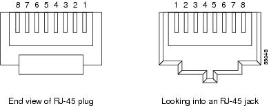
Problem When connecting your PC to the ONS 15454, you are unable to verify that the NIC connection is working properly because the link LED is not illuminated or flashing.Solution Confirm that both ends of the cable are properly inserted. If the cable is not fully inserted due to a broken locking clip, the cable should be replaced.Solution Ensure that the cable is in good condition. If in doubt, use a known-good cable. Often, cabling is damaged due to pulling or bending. (For information about installing cable, refer to the Install the Shelf and Common Control Cards chapter in the Cisco ONS 15454 DWDM Procedure Guide.)Solution If connecting an ONS 15454 directly to your laptop, a PC, or a router, use a straight-through CAT-5 cable. When connecting the ONS 15454 to a hub or a LAN switch, use a crossover CAT-5 cable. For details on the types of CAT-5 cables, see the Crimp Replacement LAN Cables.Verify PC Connection to the ONS 15454 (ping)
Solution Use a standard ping command to verify the TCP/IP connection between the PC and the ONS 15454 TCC2/TCC2P/TCC3 card. A ping command should work if the PC connects directly to the TCC2/TCC2P/TCC3 card or uses a LAN to access the TCC2/TCC2P/TCC3 card. Complete the Ping the ONS 15454.Ping the ONS 15454
Procedure
Step 1 Display the command prompt:
- If you are using a Microsoft Windows operating system, from the Start Menu choose Run, enter command in the Open field of the Run dialog box, and click OK.
- If you are using a Sun Solaris operating system, from the Common Desktop Environment (CDE) click the Personal Application tab and click Terminal.
Step 2 For both the Sun and Microsoft operating systems, at the prompt enter: ping ONS-15454-IP-address For example:
ping 198.168.10.10
Step 3 If the workstation has connectivity to the ONS 15454, the ping is successful and displays a reply from the IP address. If the workstation does not have connectivity, a Request timed out message appears. Step 4 If the ping is successful, it demonstrates that an active TCP/IP connection exists. Restart CTC. Step 5 If the ping is not successful, and the workstation connects to the ONS 15454 through a LAN, check that the workstation IP address is on the same subnet as the ONS node. Step 6 If the ping is not successful and the workstation connects directly to the ONS 15454, check that the link light on the workstation NIC is illuminated.
The IP Address of the Node is Unknown
Solution Leave one TCC2/TCC2P/TCC3 card in the shelf. Connect a PC directly to the remaining TCC2/TCC2P/TCC3 card and perform a hardware reset of the card. The TCC2/TCC2P/TCC3 card transmits the IP address after the reset to enable you to capture the IP address for login. Complete the Retrieve Unknown Node IP Address.Retrieve Unknown Node IP Address
Procedure
Step 1 Connect your PC directly to the active TCC2/TCC2P/TCC3 card Ethernet port on the faceplate. Step 2 Start the Sniffer application on your PC. Step 3 Perform a hardware reset by pulling and reseating the active TCC2/TCC2P/TCC3 card. Step 4 After the TCC2/TCC2P/TCC3 card completes resetting, it broadcasts its IP address. The Sniffer software on your PC will capture the IP address being broadcast.
CTC Operation Troubleshooting
This section contains troubleshooting procedures for CTC login or operation problems.
- CTC Colors Do Not Appear Correctly on a UNIX Workstation
- Unable to Launch CTC Help After Removing Netscape
- Unable to Change Node View to Network View
- Browser Stalls When Downloading CTC JAR Files From TCC2/TCC2P/TCC3 Card
- CTC Does Not Launch
- Slow CTC Operation or Login Problems
- Node Icon is Gray on CTC Network View
- Java Runtime Environment Incompatible
- Different CTC Releases Do Not Recognize Each Other
- Username or Password Do Not Match
- DCC Connection Lost
- Path in Use Error When Creating a Circuit
- Calculate and Design IP Subnets
CTC Colors Do Not Appear Correctly on a UNIX Workstation
Problem When running CTC on a UNIX workstation, the colors do not appear correctly. For example, both major and minor alarms appear in the same color.Possible Cause When running in 256-color mode on a UNIX workstation, color-intensive applications such as Netscape might use all of the colors.Solution CTC requires a full 24-color palette to run properly. When logging into CTC on a UNIX workstation, run as many colors as your adapter will support. In addition, you can use the -install or the -ncols 32 command line options to limit the number of colors that Netscape uses. Complete the Limit Netscape Colors. If the problem persists after limiting Netscape colors, exit any other color-intensive applications in use.Unable to Launch CTC Help After Removing Netscape
Problem After removing Netscape and running CTC using Internet Explorer, you are unable to launch CTC Help and receive an MSIE is not the default browser error message.Solution When the CTC software and Netscape are installed, the Help files are associated with Netscape by default. When you remove Netscape, the Help files are not automatically associated with Internet Explorer as the default browser. Reset Internet Explorer as the default browser so that CTC associates the Help files to the correct browser. Complete the Reset Internet Explorer as the Default Browser for CTC to associate the CTC Help files to the correct browser.Reset Internet Explorer as the Default Browser for CTC
Procedure
Step 1 Open the Internet Explorer browser. Step 2 From the menu bar, click Tools > Internet Options. The Internet Options window appears. Step 3 In the Internet Options window, click the Programs tab. Step 4 Click the Internet Explorer should check to see whether it is the default browser check box. Step 5 Click OK. Step 6 Exit all open and running CTC and Internet Explorer applications. Step 7 Launch Internet Explorer and open a new CTC session. You should now be able to access the CTC Help.
Unable to Change Node View to Network View
Problem When activating a large, multinode BLSR from Software R3.2 to Software R3.3, some of the nodes appear grayed out. Logging into the new CTC, the user is unable to change node view (single-shelf mode) or shelf view (multishelf mode) to network view on any nodes, from any workstation. This is accompanied by an Exception occurred during event dispatching: java.lang.OutOfMemoryError in the java window.Possible Cause The large, multinode BLSR requires more memory for the graphical user interface (GUI) environment variables.Solution Set the system or user CTC_HEAP environment variable to increase the memory limits. Complete the Set the CTC_HEAP and CTC_MAX_PERM_SIZE_HEAP Environment Variables for Windows or the Set the CTC_HEAP and CTC_MAX_PERM_SIZE_HEAP Environment Variables for Solaris to enable the CTC_HEAP variable change.
- Set the CTC_HEAP and CTC_MAX_PERM_SIZE_HEAP Environment Variables for Windows
- Set the CTC_HEAP and CTC_MAX_PERM_SIZE_HEAP Environment Variables for Solaris
Set the CTC_HEAP and CTC_MAX_PERM_SIZE_HEAP Environment Variables for Windows
Procedure
Note
Before proceeding with the following steps, ensure that your system has a minimum of 1 GB of RAM. If your system does not have a minimum of 1 GB of RAM, contact the Cisco Technical Assistance Center (TAC).
Step 1 Close all open CTC sessions and browser windows. Step 2 From the Windows Start menu, choose Control Panel > System. Step 3 In the System Properties window, click the Advanced tab. Step 4 Click the Environment Variables button to open the Environment Variables window. Step 5 Click the New button under the System variables field. Step 6 Type CTC_HEAP in the Variable Name field. Step 7 Type 512 in the Variable Value field, and then click the OK button to create the variable. Step 8 Again, click the New button under the System variables field. Step 9 Type CTC_MAX_PERM_SIZE_HEAP in the Variable Name field. Step 10 Type 128 in the Variable Value field, and then click the OK button to create the variable. Step 11 Click the OK button in the Environment Variables window to accept the changes. Step 12 Click the OK button in the System Properties window to accept the changes.
Set the CTC_HEAP and CTC_MAX_PERM_SIZE_HEAP Environment Variables for Solaris
Procedure
Step 1 From the user shell window, kill any CTC sessions and browser applications. Step 2 In the user shell window, set the environment variables to increase the heap size.
Example:The following example shows how to set the environment variables in the C shell:
% setenv CTC_HEAP 512
% setenv CTC_MAX_PERM_SIZE_HEAP 128
Browser Stalls When Downloading CTC JAR Files From TCC2/TCC2P/TCC3 Card
Problem The browser stalls or hangs when downloading a CTC Java archive (JAR) file from the TCC2/TCC2P/TCC3 card.Possible Cause McAfee VirusScan software might be interfering with the operation. The problem occurs when the VirusScan Download Scan is enabled on McAfee VirusScan 4.5 or later.Solution Disable the VirusScan Download Scan feature. Complete the Disable the VirusScan Download Scan.Disable the VirusScan Download Scan
Procedure
Step 1 From the Windows Start menu, choose Programs > Network Associates > VirusScan Console. Step 2 Double-click the VShield icon listed in the VirusScan Console dialog box. Step 3 Click Configure on the lower part of the Task Properties window. Step 4 Click the Download Scan icon on the left of the System Scan Properties dialog box. Step 5 Uncheck the Enable Internet download scanning check box. Step 6 Click Yes when the warning message appears. Step 7 Click OK in the System Scan Properties dialog box. Step 8 Click OK in the Task Properties window. Step 9 Close the McAfee VirusScan window.
CTC Does Not Launch
Solution Redirect the Netscape cache to a valid directory. Complete the Redirect the Netscape Cache to a Valid Directory.Redirect the Netscape Cache to a Valid Directory
Procedure
Step 1 Launch Netscape. Step 2 Open the Edit menu. Step 3 Choose Preferences. Step 4 In the Category column on the left side, expand the Advanced category and choose the Cache tab. Step 5 Change your disk cache folder to point to the cache file location. The cache file location is usually C:\ProgramFiles\Netscape\Users\yourname\cache. The yourname segment of the file location is often the same as the user name.
Slow CTC Operation or Login Problems
Problem You experience slow CTC operation or have problems logging into CTC. Problem Table 1 describes the potential cause of the symptom and the solution.
Table 7 Slow CTC Operation or Login Problems Possible Problem
Solution
The CTC cache file might be corrupted or might need to be replaced.
Search for and delete cache files. This operation forces the ONS 15454 to download a new set of Java archive (JAR) files to your computer hard drive. Complete the Delete the CTC Cache File Automatically or the Delete the CTC Cache File Manually.
Insufficient heap memory allocation.
Increase the heap size if you are using CTC to manage more than 50 nodes concurrently. See the Set the CTC_HEAP and CTC_MAX_PERM_SIZE_HEAP Environment Variables for Windows or the Set the CTC_HEAP and CTC_MAX_PERM_SIZE_HEAP Environment Variables for Solaris.
Note To avoid network performance issues, Cisco recommends managing a maximum of 50 nodes concurrently with CTC. To manage more than 50 nodes, Cisco recommends using Cisco Transport Manager (CTM). Cisco does not recommend running multiple CTC sessions when managing two or more large networks.
Delete the CTC Cache File Automatically
Before You BeginProcedure
Caution
All running sessions of CTC must be halted before deleting the CTC cache. Deleting the CTC cache might cause any CTC running on this system to behave in an unexpected manner.
Step 1 Enter an ONS 15454 IP address into the browser URL field. The initial browser window shows a Delete CTC Cache button. Step 2 Close all open CTC sessions and browser windows. The PC operating system does not allow you to delete files that are in use. Step 3 Click Delete CTC Cache in the initial browser window to clear the CTC cache.
Delete the CTC Cache File Manually
Before You BeginProcedure
Caution
All running sessions of CTC must be halted before deleting the CTC cache. Deleting the CTC cache might cause any CTC running on this system to behave in an unexpected manner.
Step 1 To delete the JAR files manually, from the Windows Start menu choose Search > For Files or Folders. Step 2 In the Search Results dialog box, enter ctc*.jar or cms*.jar in the Search for Files or Folders Named field and click Search Now. Step 3 Click the Modified column in the Search Results dialog box to find the JAR files that match the date when you downloaded the files from the TCC2/TCC2P/TCC3. Step 4 Highlight the files and press the keyboard Delete key. Step 5 Click Yes in the Confirm dialog box.
Node Icon is Gray on CTC Network View
Solution Correct the core version build as described in the Different CTC Releases Do Not Recognize Each Other.Solution Correct the username and password as described in the Username or Password Do Not Match.Solution Usually accompanied by an embedded operations channel (EOC) alarm. Clear the EOC alarm and verify the DCC connection as described in the EOC.Java Runtime Environment Incompatible
Solution The JRE contains the Java virtual machine, runtime class libraries, and Java application launcher that are necessary to run programs written in the Java programming language. The ONS 15454 CTC is a Java application. A Java application, unlike an applet, cannot rely completely on a web browser for installation and runtime services. When you run an application written in the Java programming language, you need the correct JRE installed. The correct JRE for each CTC software release is included on the Cisco ONS 15454 software CD. Complete the Launch CTC to Correct the Core Version Build. If you are running multiple CTC software releases on a network, the JRE installed on the computer must be compatible with the different software releases. Table 1 shows JRE compatibility with ONS 15454 software releases.
Table 8 JRE Compatibility Software Release
JRE 1.2.2
JRE 1.3
JRE 1.4
JRE 5.0
JRE 1.6
JRE 1.7
ONS 15454 MSTP R6.0
No
No
Yes
No
No
No
ONS 15454 MSTP R7.0
No
No
No
Yes
Yes
No
ONS 15454 MSTP R8.0
No
No
No
Yes
Yes
No
ONS 15454 MSTP R8.5
No
No
No
Yes
Yes
No
ONS 15454 MSTP R9.0
No
No
No
Yes
Yes
No
ONS 15454 MSTP R9.1
No
No
No
Yes
Yes
No
ONS 15454 MSTP R9.2
No
No
No
No
Yes
Yes
Launch CTC to Correct the Core Version Build
Procedure
Step 1 Exit the current CTC session and completely close the browser. Step 2 Start the browser. Step 3 Enter the ONS 15454 IP address of the node that reported the alarm. This can be the original IP address you logged in with or an IP address other than the original. Step 4 Log into CTC. The browser downloads the JAR file from CTC.
Different CTC Releases Do Not Recognize Each Other
Problem Different CTC releases do not recognize each other. This situation is often accompanied by the INCOMPATIBLE-SW alarm.Possible Cause The software loaded on the connecting workstation and the software on the TCC2/TCC2P/TCC3 card are incompatible.Solution This occurs when the TCC2/TCC2P/TCC3 software is upgraded but the PC has not yet upgraded the compatible CTC JAR file. It also occurs on login nodes with compatible software that encounter other nodes in the network that have a newer software version. Complete the Launch CTC to Correct the Core Version Build.
Note
Solution Remember to always log into the ONS node with the latest CTC core version first. If you initially log into an ONS node running a CTC core version of 2.2 or lower and then attempt to log into another ONS node in the network running a higher CTC core version, the lower version node does not recognize the new node.Launch CTC to Correct the Core Version Build
Procedure
Step 1 Exit the current CTC session and completely close the browser. Step 2 Start the browser. Step 3 Enter the ONS 15454 IP address of the node that reported the alarm. This can be the original IP address you logged on with or an IP address other than the original. Step 4 Log into CTC. The browser downloads the JAR file from CTC.
Username or Password Do Not Match
Possible Cause The username or password entered does not match the information stored in the TCC2/TCC2P/TCC3 card.Solution All ONS nodes must have the same username and password created to display every ONS node in the network. You can also be locked out of certain ONS nodes on a network if your username and password were not created on those specific ONS nodes. For initial login to the ONS 15454, enter the CISCO15 user name in capital letters, click Login, and use the password otbu+1, which is case-sensitive. Solution Complete the Verify Correct Username and Password. If the node has been configured for Remote Authentication Dial In User Service (RADIUS) authentication, the username and password are verified against the RADIUS server database rather than the security information in the local node database. For more information about RADIUS security, refer to the Security Reference chapter in the Cisco ONS 15454 DWDM Reference ManualSecurity Reference document.Verify Correct Username and Password
Procedure
Step 1 Ensure that your keyboard Caps Lock key is not turned on and affecting the case-sensitive entry of the username and password. Step 2 Contact your system administrator to verify the username and password. Step 3 Call Cisco Technical Support 1 800 553 2447 to have them enter your system and create a new user name and password.
DCC Connection Lost
Problem DCC connection is lost. The node usually has alarms and the nodes in the network view have a gray icon. This symptom is usually accompanied by an EOC alarm.Solution Usually accompanied by an EOC alarm. Clear the EOC alarm and verify the DCC connection as described in the Alarm Troubleshooting.Path in Use Error When Creating a Circuit
Problem While creating a circuit, you get a Path in Use error that prevents you from completing the circuit creation.Solution CTC does not remove a card or port from the available list until a circuit is completely provisioned. If two users simultaneously select the same source port to create a circuit, the first user to complete circuit provisioning gets use of the port. The other user gets the Path in Use error. Cancel the circuit creation and start over, or click Back until you return to the initial circuit creation window. The source port that was previously selected no longer appears in the available list because it is now part of a provisioned circuit. Select a different available port and begin the circuit creation process again.Timing
This section provides solutions to common timing reference errors and alarms.
- ONS 15454 Switches Timing Reference
- Holdover Synchronization AlarmHLDOVRSYNC
- Free-Running Synchronization Mode
- Daisy-Chained BITS Not FunctioningBITS daisy-chained
- Blinking STAT LED after Installing a Card
ONS 15454 Switches Timing Reference
Possible Cause The optical or building integrated timing supply (BITS) input is receiving loss of signal (LOS), loss of frame (LOF), or AIS alarms from its timing source.Possible Cause The synchronization status messaging (SSM) message is set to do not use for synchronization (DUS).Solution The ONS 15454 internal clock operates at a Stratum 3E level of accuracy. This gives the ONS 15454 a free-running synchronization accuracy of +/– 4.6 ppm and a holdover stability of less than 255 slips in the first 24 hours or 3.7 x 10⁻⁷/day, including temperature. ONS 15454 free-running synchronization relies on the Stratum 3 internal clock. Over an extended time period, using a higher quality Stratum 1 or Stratum 2 timing source results in fewer timing slips than a lower quality Stratum 3 timing source.Holdover Synchronization Alarm
Problem The clock is running at a different frequency than normal and the HLDOVRSYNC appears.Solution The clock is running at the frequency of the last known-good reference input. This alarm is raised when the last reference input fails. See the HLDOVRSYNC for a detailed description.
Note
Solution The ONS 15454 supports holdover timing per Telcordia GR-436 when provisioned for external (BITS) timing.Free-Running Synchronization Mode
Blinking STAT LED after Installing a Card
The blinking STAT LED indicates that POST diagnostics are being performed. If the LED continues to blink for more than 60 seconds, the card has failed the POST diagnostics test and has failed to boot. If the card has truly failed, an Alarm Troubleshooting is raised against the slot number with an Equipment Failure description. Check the alarm tab for this alarm to appear for the slot where the card was installed. To attempt recovery, remove and reinstall the card and observe the card boot process. If the card fails to boot, replace the card. Complete the Alarm Troubleshooting.
Warning
Solution High-performance devices on this card can get hot during operation. To remove the card, hold it by the faceplate and bottom edge. Allow the card to cool before touching any other part of it or before placing it in an antistatic bag. Statement 201
Caution
Solution Removing a card that currently carries traffic on one or more ports can cause a traffic hit. To avoid this, perform an external switch if a switch has not already occurred. Refer to the procedures in the Alarm Troubleshooting. For more information, refer to the Maintain the Node chapter in the Cisco ONS 15454 DWDM Procedure Guide.Fiber and Cabling
This section explains problems typically caused by cabling connectivity errors. It also includes instructions for crimping CAT-5 cable and lists the optical fiber connectivity levels.
Bit Errors Appear for a Traffic Card
Solution Bit errors on line (traffic) cards usually originate from cabling problems or low optical-line levels. The errors can be caused by synchronization problems, especially if pointer justification (PJ) errors are reported. Moving cards into different error-free slots will isolate the cause. Use a test set whenever possible because the cause of the errors could be external cabling, fiber, or external equipment connecting to the ONS 15454. Troubleshoot low optical levels using the Faulty Fiber-Optic Connections.Faulty Fiber-Optic Connections
Possible Cause Faulty fiber-optic connections. Fiber connection problems usually occur in conjunction with alarms.Solution Refer to the appropriate trouble-clearing procedure in Alarm TroubleshootingSolution Faulty CAT-5 cables can be the source of alarms and signal errors. Complete the Crimp Replacement LAN Cables.Solution Faulty GBICs can be the source of alarms and signal errors. See the Replace Faulty SFP or XFP Connectors.
WarningInvisible laser radiation may be emitted from disconnected fibers or connectors. Do not stare into beams or view directly with optical instruments. Statement 1051.
WarningLaser radiation presents an invisible hazard, so personnel should avoid exposure to the laser beam. Personnel must be qualified in laser safety procedures and must use proper eye protection before working on this equipment. Statement 300
- Crimp Replacement LAN Cables
- Replace Faulty SFP or XFP Connectors
- Remove SFP or XFP Connectors
- Install an SFP or XFP Connector
Crimp Replacement LAN Cables
You can crimp your own LAN cables for use with the ONS 15454. Use a cross-over cable when connecting an ONS 15454 to a hub, LAN modem, or switch, and use a LAN cable when connecting an ONS 15454 to a router or workstation. Use CAT-5 cable RJ-45 T-568B, Color Code (100 Mbps), and a crimping tool. Figure 1 shows the wiring of an RJ-45 connector. Table 1Figure 3 shows a LAN cable layout, and Table 1 shows the cable pinouts. Figure 3 shows a cross-over cable layout, and Table 2 shows the cross-over pinouts.
Table 9 LAN Cable Pinout Pin
Color
Pair
Name
Pin
1
white/orange
2
Transmit Data +
1
2
orange
2
Transmit Data –
2
3
white/green
3
Receive Data +
3
4
blue
1
—
4
5
white/blue
1
—
5
6
green
3
Receive Data –
6
7
white/brown
4
—
7
8
brown
4
—
8
Table 10 Cross-Over Cable Pinout Pin
Color
Pair
Name
Pin
1
white/orange
2
Transmit Data +
3
2
orange
2
Transmit Data –
6
3
white/green
3
Receive Data +
1
4
blue
1
—
4
5
white/blue
1
—
5
6
green
3
Receive Data –
2
7
white/brown
4
—
7
8
brown
4
—
8
Note
Odd-numbered pins always connect to a white wire with a colored stripe.
Replace Faulty SFP or XFP Connectors
Small Form-factor Pluggable (SFP)and 10-Gbps SFP (called XFP) modules are input/output devices that plug into some DWDM cards to link the port with the fiber-optic network. The type of SFP or XFP determines the maximum distance that traffic can travel from the card to the next network device. For a description of SFP and XFP modules and their capabilities, refer to the Installing the GBIC, SFP, SFP+, and XFP Optical Modules in Cisco ONS Platforms. SFP and XFP modules are hot-swappable and can be installed or removed while the card or shelf assembly is powered and running.
WarningInvisible laser radiation may be emitted from disconnected fibers or connectors. Do not stare into beams or view directly with optical instruments. Statement 1051.
WarningLaser radiation presents an invisible hazard, so personnel should avoid exposure to the laser beam. Personnel must be qualified in laser safety procedures and must use proper eye protection before working on this equipment. Statement 300
Note
SFP and XFP modules must be matched on both ends by type: SX to SX, LX to LX, or ZX to ZX.
Remove SFP or XFP Connectors
Before You BeginProcedure
WarningInvisible laser radiation may be emitted from disconnected fibers or connectors. Do not stare into beams or view directly with optical instruments. Statement 1051.
Step 1 Disconnect the network fiber cable from the SFP or XFP LC duplex connector. Step 2 Release the SFP or XFP from the slot by simultaneously squeezing the two plastic tabs on each side. Step 3 Slide the SFP out of the card slot. A flap closes over the SFP slot to protect the connector on the card.
Install an SFP or XFP Connector
Before You BeginProcedure
WarningInvisible laser radiation could be emitted from the end of the unterminated fiber cable or connector. Do not stare into the beam directly with optical instruments. Viewing the laser output with certain optical instruments (for example, eye loupes, magnifiers, and microscopes) within a distance of 100 mm could pose an eye hazard. Statement 1056
WarningClass 1 laser product. Statement 1008
Step 1 Remove the SFP or XFP from its protective packaging. Step 2 Check the label to verify that you are using a compatible SFP or XFP for the card where you want to install the connector. For a list of the SFP and XFP modules that are compatible with each card, refer to the Installing the GBIC, SFP, SFP+, and XFP Optical Modules in Cisco ONS Platforms document. Step 3 Plug the LC duplex connector of the fiber into a Cisco-supported SFP or XFP. Step 4 If the new SFP or XFP has a latch, close the latch over the cable to secure it. Step 5 Plug the cabled SFP or XFP into the card port until it clicks. To change the payload type of an SFP or XFP (called pluggable port modules [PPMs] in CTC), refer to the Provision Transponder and Muxponder Cards chapter in the Cisco ONS 15454 DWDM Procedure Guide.
Power Supply Problems
Problem Loss of power or low voltage, resulting in a loss of traffic and causing the LCD clock to reset to the default date and time.Solution The ONS 15454 requires a constant source of DC power to properly function. Input power is –48 VDC. Power requirements range from –42 VDC to –57 VDC. A newly installed ONS 15454 that is not properly connected to its power supply does not operate. Power problems can be confined to a specific ONS 15454 or affect several pieces of equipment on the site. A loss of power or low voltage can result in a loss of traffic and causes the LCD clock on the ONS 15454 to default to January 1, 1970, 00:04:15. To reset the clock, in node view (single-shelf mode) or shelf view (multishelf mode) click the Provisioning > General > General tab and change the Date and Time fields. Complete the Isolate the Cause of Power Supply Problems.
WarningOnly trained and qualified personnel should be allowed to install, replace, or service this equipment. Statement 1030
WarningDuring this procedure, wear grounding wrist straps to avoid ESD damage to the card. Do not directly touch the backplane with your hand or any metal tool, or you could shock yourself. Statement 94
Caution
Operations that interrupt power supply or short the power connections to the ONS 15454 are service-affecting.
Isolate the Cause of Power Supply Problems
Procedure
Step 1 If a single ONS 15454 show signs of fluctuating power or power loss:
Step 2 If multiple pieces of site equipment show signs of fluctuating power or power loss:
- Check the uninterruptible power supply (UPS) or rectifiers that supply the equipment. Refer to the UPS manufacturer’s documentation for specific instructions.
- Check for excessive power drains caused by other equipment, such as generators.
- Check for excessive power demand on backup power systems or batteries when alternate power sources are used.
Power Up Problems for Node and Cards
Network Level (Internode) Problems
The following network-level troubleshooting is discussed in this section:
Fiber Cut Detection
A fiber cut is one of the most disruptive faults for a DWDM system because more than one channel is potentially affected. Fault isolation must, therefore, be quick and effective.
In the Multi-Service Transport Platform (MSTP), a dedicated alarm is unambiguously associated with the detection of a fiber cut. The alarm is LOS (OTS or AOTS) and can be raised by the OPT-BST, OSC-CSM, 40-SMR1-C, and 40-SMR2-C cards that directly interface to the span fiber. The LOS (OTS or AOTS) alarm is associated with the physical LINE-RX port of the OPT-BST, OSC-CSM, 40-SMR1-C, and 40-SMR2-C cards (in CTC, identified by Port 5 on the OPT-BST, Port 4 on the OSC-CSM, Port 9 on the 40-SMR1-C, and Port 7 on the 40-SMR2-C card). LOS (OTS or AOTS) is the combination of the two alarms LOS-P (OTS or AOTS) (applies to channel payload) and LOS-O (applies to the OC-3 overhead OSC signal).
The simultaneous failure of both the active channel (C band) and the service channel (1510 nm) coming into the node is evidence of a fiber span issue, whereas either the LOS-P (OTS or AOTS) alarm alone or the LOS-O alarm alone can only be derived from different root causes.
Note
When a fiber cut occurs, the actual conditions on the affected span (for example, alarms raised on both line directions) are strictly dependent on the network automatic laser shutdown (ALS) setting. The network ALS setting is a function of the ALS mode configured on the appropriate cards in the system (OPT-BST, OPT-BST-E, OPT-BST-L, OPT-AMP-L, OPT-AMP-C, OPT-AMP-17C, 40-SMR1-C, 40-SMR2-C, OSC-CSM, and OSCM).
Different symptoms and scenarios can occur, depending on the network ALS settings. Consider the linear network (four nodes) in Figure 1 as a reference. The scenarios are presented after the figure.
Scenario A
Scenario A has the following conditions:
- ALS Mode = Auto Restart on OPT-BST (+ OSCM) and OSC-CSM
- Fiber cut on the fiber between the OLA-TX node and the ROADM-RX node
The ALS protocol (refer to the Network Optical SafetyAutomatic Laser Shutdown section in the Network Reference chapter of the Cisco ONS 15454 DWDM Reference Manual) is activated in the event of a fiber cut, resulting in the shutdown of optical power on both of the fibers belonging to the affected span, even if only one of the two fibers is cut.
The final fault condition of the network is shown in Figure 1.
In network view, both of the lines representing the span were formerly green and have now changed to gray. Notice also that the status of all the OCHNC circuits on the broken span have changed from Discovered to Partial.
In node view (single-shelf mode) or shelf view (multishelf mode), the alarm panel of the two nodes (reconfigurable optical add/drop multiplexing [ROADM] and optical line amplification [OLA] in the example) show the LOS (AOTS) alarm on Port 4 of the OSC-CSM (see Figure 2) and the LOS (OTS) on Port 5 of the OPT-BST (see Figure 3).
Note
An EOC condition is always present on both nodes, because the optical service channel (OSC) link (to which the communication channel applies) is down.
Note
For the OSCM card, only an LOS (OC-3) alarm is present at the SONET layer (Port 1).
Scenario B
Scenario B has the following conditions:
- ALS Mode = DISABLE on OPT-BST (+ OSCM) and OSC-CSM
- Fiber cut on the fiber between the OLA-TX node and the ROADM-RX node
Because the ALS protocol is disabled, the signal is lost on only the affected fiber (power is not shut down on both fibers).
The LOS (OTS or AOTS) alarm is raised by the ROADM-RX node that was receiving the signal coming from the broken fiber. The final fault condition of the network is shown in Figure 1.
In network view (Figure 1), only the actual affected fiber becomes gray, whereas the traffic (and OSC signal as well) on the good fiber is active and fault identification is immediate.
In node view (single-shelf mode) or shelf view (multishelf mode) (Figure 2 and Figure 3), the alarm panel of the receiving node (ROADM in this example) reports the LOS (OTS), while the transmitting node (OLA) reports only an EOC alarm.
In order to troubleshoot and eventually fix a fiber cut, follow the Fix a Fiber Cut. The basic assumption is that the MSTP system was already installed and working correctly before the alarm condition occurred. For first installation or restart from a fiber cut, refer to System Restart after a Fiber Cut.
Fix a Fiber Cut
Before You BeginProcedure
Caution
When the network ALS setting is DISABLE, optical power is still present at the damaged fiber. Before fixing the span, it is highly recommended that you shut down the amplifier and the OSC laser upstream of the fiber cut.
Step 1 Isolate the span affected by the fiber cut. Step 2 Verify the alarm is valid, then perform the following steps for both DWDM nodes connected to the span identified in Step 1.
Step 3 If the network ALS setting on the DWDM nodes that you are troubleshooting is Auto Restart, continue with 4; if the network ALS setting is DISABLE, go to 5.
Note The network ALS setting is a function of the ALS mode configured on the appropriate cards in the system (OPT-BST, OPT-BST-E, OPT-BST-L, OPT-AMP-L, OPT-AMP-C, OPT-AMP-17C, OSC-CSM, and OSCM).
Step 4 Isolate the fiber affected by the fiber cut. For the two fibers belonging to the span, identify the fiber belonging to the west-to-east (W–E) line direction:
Step 5 Repair the identified broken fiber to restore the internode link.
Warning Invisible laser radiation could be emitted from the end of the unterminated fiber cable or connector. Do not stare into the beam directly with optical instruments. Viewing the laser output with certain optical instruments (for example, eye loupes, magnifiers, and microscopes) within a distance of 100 mm could pose an eye hazard. Statement 1056
Note Before disconnecting any optical amplifier card fiber for troubleshooting, ensure that the optical amplifier card is unplugged.
System Restart after a Fiber Cut
When the network ALS setting is Auto Restart, the system automatically restarts after a fiber cut occurs. MSTP system restart after a fiber cut is a fully automatic process regulated by a chronological sequence of steps including the OSC link built-in amplifiers restart and amplifier power control (APC) regulation.
The successful completion of system restart is strictly related to possible changes of the insertion loss value of the repaired span. A change in insertion loss is dependent on many factors, including the process of physically repairing the fiber, a change in fiber length after repair, and so on.
Four different scenarios related to span loss are presented in this section:
- Span loss increased:
- Span loss increased:
- Span loss increased: 3 dBm < span loss change < 5 dBm
- Span loss increased: span loss change < 3 dBm
Note
It is also possible that span loss decreased, but this is unlikely. This condition does not prevent the MSTP system automatic restart process, but can lead (potentially) to issues downstream of the repaired span, for example, a Power Overload condition on the OSC receiver or on the Trunk-RX port of a TXP or MXP card.
These conditions are identified by specific alarms (see the HI-RXPOWER section in the Alarm Troubleshooting chapter).
The symptoms of the possible span loss scenarios (except for span loss decrease) are described in the following paragraphs. Refer to the linear network in Figure 1 during the discussion of the scenarios.
The basic assumption is that the network ALS feature (for feature details, refer to the Network Optical Safety––Automatic Laser Shutdown section in the Network Reference chapter of the Cisco ONS 15454 DWDM Reference Manual) is active (ALS Mode = Auto Restart on the OPT-BST, OPT-AMP-x-C, [+ OSCM] and OSC-CSM). Given this assumption, the starting condition is as shown in Figure 1.
The system behavior when the network ALS Mode is DISABLE is a subcase that requires a manual restart after repairing a single fiber in only one line direction.
Note
The network ALS feature is a function of the ALS Mode settings of the OPT-BST, OPT-BST-E, OPT-BST-L, OPT-AMP-L, OPT-AMP-x-C, OPT-RAMP-C, OSCM, and OSC-CSM cards. For the network ALS Mode to be disabled, each of these cards must have its ALS Mode set to DISABLE.
- Scenario 1: Span Loss Change > 5 dBm and OSC Power Value on the Receiver less than –42 dBm
- Scenario 2: Span Loss Change > 5 dBm and OSC Power Value on the Receiver > –42 dBm
- Scenario 3: 3 dBm less than Span Loss Change less than 5 dBm
- Scenario 4: Span Loss Change less than 3 dB
Scenario 1: Span Loss Change > 5 dBm and OSC Power Value on the Receiver less than –42 dBm
In network view, both of the lines representing the span remain gray as long as the status of the OCHNC circuits relating to the repaired span remain in Partial state.
In node view (single-shelf mode) or shelf view (multishelf mode), the alarm panels of the two nodes (ROADM and OLA in this example) show the LOS (OTS or AOTS) condition on the LINE-RX port of the OPT-BST, OPT-AMP-x-C, or OSC-CSM.
An EOC condition is always present on both nodes because the OSC optical link is down due to an incoming power level lower than the optical sensitivity limit (–42 dBm). The system condition remains unchanged as illustrated in Scenario A.
Every 100 seconds, the ALS protocol turns up the OSC TX laser in a pulse mode (pulse duration = 2 seconds), but the excessive loss on the span prevents the OSC link from synchronizing, and the MSTP system remains unoperational.
Note
During the attempt to restart, a valid power value is reported by the OSC transmit card (in the example, the OSC-CSM in the OLA node), but on the OSC receive card (the OSCM in the ROADM node), the alarm condition persists.
Corrective Action for Scenario 1
Procedure
Step 1 Follow these steps to verify the alarms for both DWDM nodes that are connected to the repaired span:
Step 2 Isolate the fiber affected by the excessive insertion loss. For the two fibers belonging to the span, identify the one for the W–E line direction.
Step 3 For the two fibers belonging to the repaired span, identify one for the east to west (E–W) line direction. Step 4 Repeat the procedure starting at Step 2 for the E–W direction. Step 5 Clean the LINE-RX and LINE-TX connectors for the failing fiber that was identified in the previous steps. Step 6 If the problem persists, continue with Step 7. Otherwise, the corrective action is finished. Step 7 Repair the failing fiber again until the expected OSC link is reestablished.
Warning Invisible laser radiation could be emitted from the end of the unterminated fiber cable or connector. Do not stare into the beam directly with optical instruments. Viewing the laser output with certain optical instruments (for example, eye loupes, magnifiers, and microscopes) within a distance of 100 mm could pose an eye hazard. Statement 1056
Note Before disconnecting any optical amplifier card fiber for troubleshooting, ensure that the optical amplifier card is unplugged.
Note If the OSC link cannot be reestablished (either by splicing or replacing the fiber), and the new value of Span Loss cannot be modified, log into the Technical Support Website at http://www.cisco.com/techsupport for more information or call Cisco TAC (1 800 553-2447) in order to report a service-affecting problem.
Scenario 2: Span Loss Change > 5 dBm and OSC Power Value on the Receiver > –42 dBm
In network view, both of the lines representing the span change to green; however, the status of the OCHNC circuits relating to the repaired span remains Partial, instead of Complete (due to the fiber cut).
This change is due to the fact the physical optical power value received by the OSC transceiver is above the sensitivity limit (–42 dBm) and consequently, the OSC optical link can be rebuilt, allowing the restoration of the Section DCC (SDCC) or multiplex section DCC (MS-DCC). The network view for this condition is shown in Figure 1.
In node view (single-shelf mode) or shelf view (multishelf mode), the EOC condition is cleared, but the alarm panels of the two nodes (ROADM and OLA in the example) continue to show LOS (OTS or AOTS) on the LINE-RX port of the OPT-BST, OPT-AMP-x-C, or OSC-CSM.
The network ALS protocol keeps the OCHNC traffic down along the span because the new losses of the restored span can potentially affect the optical validation of the network design done by Cisco TransportPlanner.
Corrective Action for Scenario 2
Procedure
Step 1 Verify the validity of the alarm. Step 2 For both DWDM nodes connected to the repaired span:
Step 3 Measure the new Span Loss value after fixing the fiber.
Step 4 Compare the span measurements of Step 3 with the span losses values used during the network design with Cisco TransportPlanner. Step 5 For the two fibers belonging to the repaired span, identify the fiber for the W–E line direction and calculate the insertion loss variation. If the span loss change is greater than 3 dBm, continue with Step 6. If not, go to Step 9. Step 6 Clean the LINE-RX and LINE-TX connectors on the DWDM cards managing the fiber of the repaired span. If the problem persists, continue with Step 7. Step 7 If the alarm condition is still reported, it is recommended that the fiber be repaired again to reestablish the expected span loss value. If this is not possible and the new value of span loss cannot be modified, go to Step 8 to fix the system faulty condition.
Warning Invisible laser radiation could be emitted from the end of the unterminated fiber cable or connector. Do not stare into the beam directly with optical instruments. Viewing the laser output with certain optical instruments (for example, eye loupes, magnifiers, and microscopes) within a distance of 100 mm could pose an eye hazard. Statement 1056
Note Before disconnecting any optical amplifier card fiber for troubleshooting, ensure that the optical amplifier card is unplugged.
Step 8 Follow the signal flow into the network starting from the repaired fiber:
Step 9 For the two fibers belonging to the repaired span, identify the fiber for the east to west (E–W) line direction. Step 10 Repeat the procedure from Step 5 to Step 8 for the E–W direction. Step 11 If the LOS alarm has cleared, the system has restarted properly. However, because a significantly different span loss value is now present, we highly recommended that you complete the following steps:
Step 12 Go back to the card where the LOS alarm is active, and set the optic thresholds (see Step 8b) to the lowest value allowed. If an OPT-BST or OPT-AMP-x-C is present:
If an OSC-CSM is present:
Note If the LOS alarm is still present, log into the Technical Support Website at http://www.cisco.com/techsupport for more information or call Cisco TAC (1 800 553-2447) in order to report a service-affecting problem.
Step 13 If the LOS alarm is has cleared, the system has restarted properly, but because a Span Loss value significantly different from the design is now present, we highly recommend that you repeat the steps described in Step 11.
Scenario 3: 3 dBm less than Span Loss Change less than 5 dBm
In network view, both of the lines representing the span change to green after the rebuild of the OSC optical link and consequent restoration of the SDCC or MS-DCC. The EOC condition and the LOS alarms are cleared.
The network ALS protocol successfully restarts the amplifiers, which enables the OCHNC traffic restoration along the span.
The reactivation of the OCHNC circuits relating to the repaired span (the status changes from Partial to Complete) can lead to several final conditions that depend on the network topology and node layout.
The rebuilding of circuits automatically triggers the APC check mechanism (for details, refer to the Network Reference chapter of the Cisco ONS 15454 DWDM Reference Manual). The APC check mechanism impacts the optical gain of the amplifiers (primarily the OPT-PRE card) and the VOA express attenuation for the optical add/drop multiplexing (OADM) cards. The APC application acts on the appropriate cards downstream of the repaired span (for each line direction), and attempts to compensate for the introduction of excess loss.
Because the loss increase exceeds the maximum variation (+/3 dBm) for which APC is allowed to compensate, an APC-CORRECTIO N-SKIPPED condition is raised by the first node along the flow detecting the event. The condition panel of the impacted node (the ROADM, in this example) reports the APC-CORRECTION-SKIPPED condition and indicates the port or card to which it applies.
Corrective Action for Scenario 3
Procedure
Step 1 Verify the alarm validity. Step 2 For both DWDM nodes connected to the repaired span:
Step 3 Measure the new Span Loss value after the fiber has been repaired.
Step 4 Compare the Span Measurements of the previous step with the Span Losses values used during the network design with Cisco TransportPlanner. Step 5 For the two fibers belonging to the repaired span, identify the one for the W–E line direction. If the Span Loss Change is greater than 3 dB, continue with 6. If not, go to 9. Step 6 Clean the LINE-RX and LINE-TX connectors of the DWDM cards that manage the fiber of the repaired span. If the problem persists, continue with Step 7. Otherwise, you are finished with the corrective action. Step 7 If the alarm condition is still reported, we recommend that you again repair the fiber to reestablish the expected span loss value. If this is not possible and the new value of Span Loss cannot be modified, move to Step 8 to fix the system faulty condition.
Warning Invisible laser radiation could be emitted from the end of the unterminated fiber cable or connector. Do not stare into the beam directly with optical instruments. Viewing the laser output with certain optical instruments (for example, eye loupes, magnifiers, and microscopes) within a distance of 100 mm could pose an eye hazard. Statement 1056
Note Before disconnecting any optical amplifier card fiber for troubleshooting, ensure that the optical amplifier card is unplugged.
Step 8 Follow the signal flow into the network starting from the repaired fiber.
Step 9 For the two fibers belonging to the repaired span, identify the fiber for to the east to west (E–W) line direction. Step 10 Repeat the procedures from 6 to 8 for the E–W direction.
Scenario 4: Span Loss Change less than 3 dB
In network view, both the lines that represent the span turn green after the rebuilding of the OSC optical link and consequent restoration of the SDCC or MS-DCC. The EOC condition and LOS alarms are cleared.
The network ALS protocol successfully completes the amplifier restart to enable OCHNC traffic restoration along the span.
The rebuilding of circuits automatically triggers the APC check mechanism (for details, refer to the Network Reference chapter of the Cisco ONS 15454 DWDM Reference Manual). The APC check mechanism affects the optical gain of the amplifiers (primarily the OPT-PRE) and the VOA express attenuation for the OADM cards. The APC application acts on the suitable cards downstream of the repaired span (for each line direction), and attempts to compensate for the introduction of excess loss.
The APC operation is successfully completed if enough margin during the Cisco Transport Planner network design phase has been taken into account. If not, the adjustment done by the APC application overcomes the range setting for a specific optical parameter in the first appropriate card along the flow and an APC-OUT-OF-RANGE condition is raised. The condition panel of the impacted node (the ROADM in the example) reports the APC-OUT-OF-RANGE condition and indicates the port or card to which it applies.
Corrective Action for Scenario 4
Procedure
Step 1 Verify the alarm validity. Step 2 For both DWDM nodes on the repaired span:
Step 3 Measure the new Span Loss value after the fiber is repaired.
Step 4 Compare the Span Measurements done in 3 with the Span Losses values used during the network design with Cisco TransportPlanner. Step 5 For the two fibers belonging to the repaired span, identify the one for the W–E line direction. Step 6 Clean the LINE-RX and LINE-TX connectors of the DWDM cards that manage the fiber of the repaired span. Step 7 If the problem persists, continue with the next step. If not, you have finished the corrective action. Step 8 If the Span Loss Change is greater than 1 dBm and the APC-OUT-OF-RANGE condition still exists, it is mandatory to again repair the fibers to reestablish the expected span loss value.
Warning Invisible laser radiation could be emitted from the end of the unterminated fiber cable or connector. Do not stare into the beam directly with optical instruments. Viewing the laser output with certain optical instruments (for example, eye loupes, magnifiers, and microscopes) within a distance of 100 mm could pose an eye hazard. Statement 1056
Note Before disconnecting any optical amplifier card fiber for troubleshooting, ensure that the optical amplifier card is unplugged.
Note If this is not possible and the new value of Span Loss cannot be modified, log into the Technical Support Website at http://www.cisco.com/techsupport for more information or call Cisco TAC (1 800 553-2447) in order to report a service-affecting problem
Step 9 For the two fibers belonging to the repaired span, identify the fiber for the east to west (E–W) line direction. Step 10 Repeat the procedure from 6 to 8for the E–W direction.
OCHNC Circuits Creation Failure
OCHNC circuit creation is managed by the Cisco Wavelength Path Provisioning (WPP) network application. The WPP application helps prevent errors during new circuit activation (if the wavelength is already allocated in the path between source and destination) and also guarantees an appropriate time interval between one circuit activation and the next to enable proper amplifier gain regulation by APC.
WPP uses the network topology information carried by the OSC link among different nodes to identify the routing path of the optical wavelength (OCHNC circuits) from the source node to the destination node. WPP also enables the card ports of the OCHNC circuits by changing the administrative state from the default (OOS or Locked) state to the final (IS or Unlocked) state.
- Prerequisites for Successful OCHNC Circuit Creation
- Conditions for OCHNC Circuit Creation Failure
- Scenarios for OCHNC Circuit Creation Failure
Prerequisites for Successful OCHNC Circuit Creation
The prerequisite conditions for successfully completed circuit creation are:
- Internode: OSC link active among all DWDM nodes involved
- Internode: APC enabled (or alternatively manually disabled by the user)
- Intranode: Logical connections among cards created and provisioned on every node of the network (ANS completed)
Note
For more information about these operations, refer to the NTP-G183 Diagnose and Fix OCHNC and OCH Trail Circuits section in Create Optical Channel Circuits and Provisionable Patchcords chapter in the Cisco ONS 15454 DWDM Procedure Guide.
OCHNC circuit creation is successfully completed when the CTC circuit table reports the situation shown in Figure 1.
Conditions for OCHNC Circuit Creation Failure
If the OCHNC circuit creation fails, you will see one of the following conditions:
- If the WPP wizard cannot complete the circuit creation procedure, CTC displays the error message shown in Figure 1. In the message, click Details to see the partial connections that WPP can set up. Start troubleshooting the problem in the first node that is unreachable along the path.
- The circuit is successfully created and reported under the Circuits tab, the Status field turns to DISCOVERED, but the Circuit State is OOS (locked). The condition is shown in Figure 2 .
- The OCHNC circuit is shown under the Circuits tab, but the Status field reports PARTIAL. This applies to a circuit successfully built-up when the network falls into scenarios a. or b (OSC link fail or APC disabled), described below.
The root cause identification for the preceding conditions are found in the prerequisite conditions described in Prerequisites for Successful OCHNC Circuit Creation.
Scenarios for OCHNC Circuit Creation Failure
The most common scenarios for failure to create an OCHNC circuit are:
- One (or more) of the Span OSC links involving the OCHNC circuit has not been properly established. The WPP application prevents the creation of any circuit passing through the failing span. Prerequisite condition of Prerequisites for Successful OCHNC Circuit Creation has not been met.
- The APC application is internally disabled due to the presence of a Critical alarm somewhere in the network. As a consequence, no reliable information about the number of active channels can be shared among the nodes and the creation of any further OCHNC circuit is prevented until the faulty condition is fixed. Prerequisite condition 1 of Prerequisites for Successful OCHNC Circuit Creation has not been met.
- One (or more) of the intranode connections between two DWDM cards associated with the circuit have not been properly created. Prerequisite condition of 2 Prerequisites for Successful OCHNC Circuit Creation has not been met.
- One (or more) of the intranode connections between two DWDM cards associated with the circuit have not been properly provisioned. This happens when ANS application has not run in one of the involved nodes or at least one port status after the ANS run has not been successfully configured (Fail-Out of Range alarm on the ANS panel). Prerequisite condition 3 of Prerequisites for Successful OCHNC Circuit Creation has not been met.
To troubleshoot and eventually fix issues related to the faulty OCHNC circuit creation shown in Figure 1, the following procedure must be performed.
Corrective Action
Procedure
Step 1 Verify OSC connectivity:
Step 2 Verify APC status:
Step 3 Verify that the intranode connections have been built in: Step 4 Verify that all node connections have been created and that their state is Connected.
Tip To quickly verify the connections, click the Calculate Connection button and check to see if any new connections come up.
If some connections are missing, perform the proper procedure according to Turn Up a Node in the Cisco ONS 15454 DWDM Procedure Guide.
Step 5 If necessary, log into the Technical Support Website at http://www.cisco.com/techsupport for more information or call Cisco TAC (1 800 553-2447) in order to report a service-affecting problem.
Node Level (Intranode) Problems
Troubleshooting for node-level optical channel (OCH) VOA start-up failure as well as internal VOA control loop problems in the amplifier cards (OPT-BST, OPT-BST-L, OPT-PRE, OPT-AMP-17-C, OPT-AMP-C, OPT-AMP-L, and OPT-BST-E); demultiplexer cards (32-DMX, 32-DMX-L, 40-DMX-C, and 40-DMX-CE) having a single variable optical attenuator (VOA); and optical add/drop multiplexer cards (AD-1C-xx.x, AD-2C-xx.x, AD-4C-xx.x, AD-1B-xx.x, and AD-4B-xx.x) that occur due to counter-propagating light are discussed in this section.
A dedicated VOA regulates the optical power for every single channel (single wavelength) inserted in the MSTP system through a WSS, 32MUX-O, or AD-xC-xx.x card.
The final state for the VOAs is the power control working mode. In this mode, the attenuation that the VOA introduces is automatically set based on the feedback provided from a dedicated photodiode, so that a specific power setpoint value is reached and maintained.
- VOA Startup Phases
- VOA Failure Scenarios
- Counter-Propagating Light Affecting Operation of 32DMX-C and 32DMX-L Cards
VOA Startup Phases
The final VOA condition is achieved through a startup procedure divided into the four sequential phases shown in Figure 1.
Until the VOA has completed all the phases shown in Figure 1, the power control mode is not fully activated.
Phase 1: Incoming Signal Validation
The Incoming Signal Validation phase checks to see that the optical interface connection is valid and that the optical power level is appropriate.
Cisco TransportPlanner calculates the VOA Attenuation Reference value to allow only supported MSTP interfaces to overcome the power start-up (Pstart-up) acceptance level. (Refer to the Network Reference chapter of the Cisco ONS 15454 DWDM Reference Manual.)
If the interface that is connected has a power value outside the allowed range, the Phase 1 check prevents OCHNC turn-up.
Phase 2: Valid Signal Detected
If Phase 1 indicates that the signal is valid, an automatic iterative attenuation adjustment on the VOA takes place to reach a power target on the photodiode downstream of the VOA.
Note
The power setpoint is generated by Cisco TransportPlanner on a case-by-case basis. During the ANS run, the power target is provisioned on the VOA.
Phase 3: Channel Power Setpoint Locking
In Phase 3, the VOA is kept in a transient standby condition when a steady power value close enough to the final power setpoint has been reached (nominally 3 dBm lower).
The duration of the transient standby condition is three seconds (by default) and allows safe management of optical interfaces that have different signal rise time values or are undergoing a pulse startup procedure compliant with the ITU-T G664 recommendation.
Phase 4: Channel Power Control Mode Fully Activated
The VOA reaches the final attenuation condition that leads the power value that is read on the photodiode to the expected target value (VOA Power Reference). Simultaneously, the VOA operating mode switches to power control mode.
From this point on, any further adjustment of the VOA attenuation is triggered by a variation of the value read on the photodiode. The aim of these adjustments is to always keep the power value equal to the power setpoint, with +/ 0.5 dBm as the minimum adjustment increment.
VOA Failure Scenarios
Several conditions can stop the startup procedure at an intermediate step, blocking the VOA (and the circuit activation, as a consequence) from completing activation of the power control mode. The scenarios in this section portray those conditions.
Root-cause identification can be performed based on the alarm raised and the power reading on the photodiode associated with the VOA.
- Scenario A: Optical Power Level of the Incoming Signal Lower Than Minimum Allowed by MSTP Supported Optical Interfaces
- Scenario B: Optical Power Level of the Incoming Signal Lower Than Expected
- Corrective Actions for Scenario B (Optical Power Level of Incoming Signal Lower than Expected)
- Scenario C: Optical Drop Power Level Lower Than Expected
- Corrective Action for Scenario C (Optical Power Level of Incoming Signal Lower than Expected)
Scenario A: Optical Power Level of the Incoming Signal Lower Than Minimum Allowed by MSTP Supported Optical Interfaces
This scenario is for a condition where a TXP or MXP card is directly connected to a 32MUX-O, 40MUX, 32WSS, or 40WSS-C card where power in is expressed as Pin < –4.5 dBm.
If the incoming power level is lower than the minimum allowed, the startup procedure always stops at Phase 1 (see Figure 1). This is the case even if the final VOA Power Reference reported in CTC is reachable.
The final conditions that CTC reports are:
- A LOS-P (OCH layer) alarm on the port associated with the VOA (see Figure 1)
- A valid optical power value (different from the end of scale value of – 50 dBm) in the Power field, but the value for Power is less than –33 dBm. (To view the Power field, in card view, click the Provisioning > Parameters tabs.)
Use the following procedure to troubleshoot and eventually fix issues related to the VOA start-up when the optical power level of the incoming signal is lower than the minimum allowed by the MSTP supported optical interfaces.
Corrective Action for Scenario A
Procedure
Step 1 Verify the alarm validity:
Step 2 If the alarmed card is a 32WSS or 40WSS-C, verify the incoming power level from the connected TXP, MXP, or line card. If the alarmed card is a 32MUX-O or 40MUX, go to Step 5.
Step 3 Because the actual power received by the WSS card is lower than expected, verify the correct behavior of the TXP, MXP, or line card connected to the WSS:
- The TX laser must be active (trunk port is in IS [or Unlocked] state).
- The wavelength provisioned must be the proper one.
- The output power value must be within the expected range (refer to the Hardware Specifications appendix in the Cisco ONS 15454 DWDM Reference Manual). If the trunk port PM is not available through CTC, perform a manual measurement using a standard power meter.
If the TX laser is active, the wavelength is provisioned properly, and the output power value is in the correct range, go to Step 4. Otherwise, take the appropriate corrective action, including card replacement if the output power value is outside of the expected range (refer to the Upgrade, Add, and Remove Cards and Nodes chapter of the Cisco ONS 15454 DWDM Procedure Guide. Replacing the card should correct the problem.)
Warning High-performance devices on this card can get hot during operation. To remove the card, hold it by the faceplate and bottom edge. Allow the card to cool before touching any other part of it or before placing it in an antistatic bag. Statement 201
Step 4 If the TXP or MXP card behaves as expected, the only remaining root cause is the fiber connection between the two cards:
Step 5 When the alarmed card is a 32MUX-O or 40MUX, the troubleshooting procedure should start from the TXP, MXP, or line card. Verify the correct behavior of the TXP, MXP, or line card connected to the 32MUX-O or 40MUX:
- The TX laser must be active (trunk port is in IS [or Unlocked] state).
- The wavelength provisioned must be the proper one.
- The output power value must be within the expected range (refer to the Hardware Specifications appendix in the Cisco ONS 15454 DWDM Reference Manual). If the trunk port PM is not available through CTC, perform a manual measurement using a standard power meter.
If the TX laser is active, the wavelength is provisioned properly, and the output power value is in the correct range, go to Step 6. Otherwise, take the appropriate corrective action, including card replacement if the output power value is outside of the expected range (refer to the Upgrade, Add, and Remove Cards and Nodes chapter of the Cisco ONS 15454 DWDM Procedure Guide. Replacing the card should correct the problem.)
Step 6 If the TXP or MXP card behaves as expected, check the fiber connection between the two cards:
Step 7 Verify the correct behavior of the VOA inside the 32MUX-O or 40MUX card:
Scenario B: Optical Power Level of the Incoming Signal Lower Than Expected
In some cases, the pass-through channels on the WSS card or the optical bypass channels on the 32MUX-O or 40MUX card are at a power level that is lower than expected. The incoming power level can be lower than expected for several reasons. A few examples are:
When the power is lower than expected, the start-up procedure can stop at Phase 1, Phase 2, or Phase 3 . The point at which the start-up procedure stops depends on the amount of power missing.
Given that Delta Power is the amount of optical power missing compared to the expected value, two final conditions for Scenario B can be identified, Conditions B1 and B2.
- Condition B1—Delta Power > 6 dB (LOS-P Alarm)
- Condition B2—Delta Power less than 6 dB (OPWR-LowDEGrade Alarm)
Condition B1—Delta Power > 6 dB (LOS-P Alarm)
When the optical power is more than 6 dB lower than the expected value, the final VOA Power Reference setpoint value is definitively not reachable and even Phase 1 of the start-up procedure cannot be properly completed. As a consequence, the final condition reported in CTC is the same as that of Scenario A:
- A LOS-P (OCH layer) alarm is present on the port associated with the VOA.
- A valid optical power value (different from the end of scale value of – 50 dBm) can be read in the Power field, but the value for Power is less than –33 dBm. (To access this value, in card view, click the Provisioning > Parameters tabs.)
Condition B2—Delta Power less than 6 dB (OPWR-LowDEGrade Alarm)
When the optical power is less than 6 dB lower than the expected value, even if a valid incoming signal is present, the final VOA Power Reference setpoint value that is reported in the CTC is not reachable and the VOA startup procedure is stopped at Phase 3.
The final conditions that CTC reports are:
- An OPWR-LowDEGrade (OCH layer) alarm is present on the port associated with the VOA.
- A valid optical power value (different from the end of scale value of –50 dBm) can be read in the Power field, but the value is (VOA Power Ref – 6 dBm) < Power < VOA Power Ref. To access this value, in card view, click the Provisioning > Parameters tabs.
Corrective Actions for Scenario B (Optical Power Level of Incoming Signal Lower than Expected)
When the optical power level of the incoming signal is lower than expected for the pass-through channels on the WSS or the optical bypass channels on the 32MUX-O or 40MUX card, use the following procedures to troubleshoot and eventually fix issues related to VOA start-up. According to the final conditions reported by the card (either LOS-P alarm for condition B1 or OPWR-LowDEGrade for condition B2), two troubleshooting procedures are suggested. These procedures are given in the following sections.
Condition B1 - LOS-P Alarm
Procedure
Step 1 Verify the alarm validity:
Step 2 In card view, click Circuits and retrieve the node, card, and port information for the alarmed channel from the Source field of the OCHNC circuit. Then follow the procedures of 3 (32MUX-O, 32WSS, 40MUX, 40WSS-C, or AD-xC-xx.x card) or 4 (TXP, MXP, or line card) as appropriate. Step 3 Verify the correct behavior of the far-end DWDM card (32MUX-O, 32WSS, 40MUX, 40WSS-C, or AD-xC-xx.x) that manages the channel (wavelength):
Step 4 Verify the correct behavior of the TXP, MXP, or line card that is the signal source of the channel (wavelength) that is alarmed:
- The TX laser must be active (trunk port is in IS [Unlocked] state).
- The wavelength provisioned must be the proper one.
- The output power value must be within the expected range (refer to the Hardware Specifications appendix in the Cisco ONS 15454 DWDM Reference Manual). If the trunk port PM is not available through CTC (for example, TXP_MR_2.5G), perform a manual measurement using a standard power meter.
Step 5 If the cards referenced in 3 and 4 are operating properly, go to 6. If not, take the appropriate corrective actions according to the alarm raised on the card. Step 6 If the alarmed card is a 32MUX-O or 40MUX, go to 9. Step 7 If the alarmed card is a 32WSS or 40MUX, continue with the following steps:
Step 8 To unambiguously pinpoint the root cause of the alarm, verify the proper cabling of the EXP_RX port (which is the common input port for all the pass-through channels) on the 32WSS or 4-WSS-C card:
Step 9 Verify the correct behavior of the VOA inside the 32MUX-O or 40MUX card:
Step 10 To unambiguously pinpoint the root cause of the alarm, verify the proper cabling of the alarmed ADD_RX port on the 32MUX-O or 40MUX card:
Condition B2 - OPWR-LowDEGrade Alarm
Procedure
Step 1 Verify the alarm validity:
Step 2 In card view, click Circuits and retrieve the node, card, and port information for the alarmed channel from the Source field of the OCHNC circuit. Then, follow the procedures in Step 3 (for 32MUX-O, 32WSS, 40MUX, 40WSS-C, or AD-xC-xx.x cards) or Step 4 (for TXP, MXP, or line cards) as appropriate. Step 3 Verify the correct behavior of the far-end DWDM card (32MUX-O, 32WSS, 40MUX, 40WSS-C, or AD-xC-xx.x) that manages the channel (wavelength). To do this, verify that the power value coming in on the ADD_RX port is correct:
Step 4 Verify the correct behavior of the TXP, MXP, or line card that is the signal source of the channel (wavelength) that is alarmed:
- The TX laser must be active (trunk port is in IS [unlocked] state).
- The wavelength provisioned must be the proper one.
- The output power value must be within the expected range (refer to the Hardware Specifications appendix in the Cisco ONS 15454 DWDM Reference Manual). If the trunk port PM is not available through CTC, perform a manual measurement using a standard power meter.
Step 5 If the cards referenced in Step 3 and Step 4 are operating properly, go to Step 6. If not, take the appropriate corrective actions according to the alarm raised on the card (see Alarm Troubleshooting). Step 6 If the alarmed card is a 32MUX-O or 40MUX card, go to Step 8. Step 7 If the alarmed card is a 32WSS or 40WSS-C card, verify the proper cabling of the EXP_RX port (common input port for all pass-through channels) on the WSS card:
Step 8 Verify the proper cabling of the alarmed ADD_RX port on the 32MUX-O or 40MUX card:
Scenario C: Optical Drop Power Level Lower Than Expected
This scenario describes the condition in which the optical power at the 32DMX-O or 40DMX drop channels is lower than expected. The 32DMX-O card is equipped with a VOA for each wavelength, and each VOA manages the power for one dropped wavelength.
The failing scenarios during the OCHNC turn-up and consequent VOA startup are the same as those described in the Scenario B: Optical Power Level of the Incoming Signal Lower Than Expected. The only difference is the type of alarm that is raised when the condition exists in which Delta Power is greater than 6 dB.
- Condition C1—Delta Power > 6 dB Lower than Expected
- Condition C2—Delta Power less than 6 dB Lower than Expected
Condition C1—Delta Power > 6 dB Lower than Expected
When the optical power on the dropped channel is more than 6 dB lower that the value expected, the final VOA Power Reference setpoint value is definitively not reachable. As a consequence, the final conditions reported in CTC are as follows:
- An OPWR-LFAIL (OCH layer) alarm is present on the port associated with the VOA.
- A valid optical power value (different from the end of scale value of –50 dBm) can be read in the CTC Power field, but the Power value is less than –33 dBm. (To view this value in card view, click the Provisioning > Parameters tabs.)
Condition C2—Delta Power less than 6 dB Lower than Expected
If the delta power is less than 6 dB lower than expected, the final conditions reported in CTC are the same as those reported for Condition B2 (see the Condition B2—Delta Power less than 6 dB (OPWR-LowDEGrade Alarm)):
- Αn OPWR-LowDEGrade (OCH layer) alarm is present on the port associated with the VOA.
- A valid optical power value (different from the end of scale value of –50 dBm) can be read in the CTC Power field, but the value is (VOA Power Ref – 6 dBm) < Power < VOA Power Ref. To view this value in card view, click the Provisioning > Parameters tabs.
A dirty connection or excessive loss of the incoming span are among the possible reasons that can lead to a fault condition. They are the most common and affect all wavelengths, whereas an excessive amplifier gain tilt or a wavelength misconfiguration on the far-end TXP or MXP card can lead to condition where only a single wavelength fails.
Corrective Action for Scenario C (Optical Power Level of Incoming Signal Lower than Expected)
Scenario C1 - LOS-P Alarm
Procedure
Step 1 Verify the alarm validity:
Step 2 Verify the correct behavior of the far-end DWDM card (32MUX-O, 32WSS, 40MUX, 40WSS-C, AD-xC-xx.x) that manages the channel (wavelength), and the TXP, MXP, or line card that is the signal source of the channel (wavelength) alarmed:
Step 3 Verify the correct behavior of the VOA inside the 32DMX-O or 40DMX card:
Step 4 To unambiguously pinpoint the root cause of the alarm, verify the proper cabling of the COM-RX port (common input port for all the drop channels) of the alarmed 32DMX-O or 40DMX card:
Scenario C2 - OPWR-LowDEGrade Alarm
Procedure
Step 1 Verify the alarm validity:
Step 2 Verify the correct behavior of the far-end DWDM card (32MUX-O, 32WSS, 40MUX, 40WSS-C, or AD-xC-xx.x) that manages the channel (wavelength) and the TXP, MXP, or line card that is the signal source of the channel (wavelength) alarmed.
Step 3 Verify the proper cabling of the COM-RX port (the common input port for all of the drop channels) of the alarmed 32DMX-O or 40DMX:
Counter-Propagating Light Affecting Operation of 32DMX-C and 32DMX-L Cards
Problem The in-service operation of the 32DMX-C and 32DMX-L cards (with vendor ID 2049 and 2050) can be seriously affected by the counter-propagating light travelling from the drop ports of the card towards the COM RX port. This counter-propagating light affects the internal VOA control loop of the vendor-specific optical module of the 32DMX-C and 32DMX-L cards, leading to an increased optical path attenuation. This is traffic affecting for all in-service channels.Possible Cause The counter-propagating light can be inserted into the 32DMX-C or 32DMX-L card as a result of incorrect cabling of transponder or line cards to the fiber patch-panel (in particular, swapping RX with TX patchcords).Solution For software releases higher than or equal to 9.0, the vendor-specific optical module on all the cards is automatically upgraded to a newer version. The vendor ID of the new version of the card is 2051 and can be viewed at CTC > Card View > Inventory tab. This new version of the optical module makes the VOA control robust to counter-propagating light, thus, minimizing the effects of incorrect cabling during installation and/or maintenance. Solution For software releases lower than 9.0, for new 32DMX-C and 32DMX-L cards that are not already installed, the vendor-specific optical module on all these new cards is automatically upgraded to a newer version at the Cisco Spare depots. Once the new card is installed in field, a downgrade of the optical module will be prevented and the latest optical module version is preserved on the software package. If the 32DMX-C or 32DMX-L card is already installed, complete the Corrective Action for Software Releases Lower than 9.0 to manually fix the problem.Corrective Action for Software Releases Lower than 9.0
Procedure
Step 1 If the TXP card is preprovisioned in CTC, but not installed: Step 2 Install the TXP card into the receptacle at the back of the designated slot. Step 3 Wait for the TXP card to boot completely. Step 4 Verify that the Trunk-TX port of the TXP card is in OOS,DSBLD (ANSI) or Locked,disabled (ETSI) state. Step 5 Wire the Trunk-TX/RX port of the TXP card to the fiber patch-panel. Step 6 Turn up the TXP card and display card view for the TXP card in CTC. Step 7 Click the Provisioning > Line tab and choose IS,AINS (ANSI) or Unlocked,automaticInService (ETSI) from the Admin State drop-down list for the Trunk-TX port. Step 8 Display card view for the 32WSS card. Step 9 Click the Performance > Optical Chn tab and verify the Power ADD field on the CHAN-RX port of the 32WSS card connected to the TXP card.
Controller Card Compatibility
The following table lists the platform and software release compatibility matrix for controller cards.
Table 11 Platform and Software Release Compatibility Matrix for Controller Cards Release Number
AIC-I, MS-ISC-100T, TCC2, TCC2P
TCC3
TNC
TSC
TNCE
TSCE
R4.5
15454-DWDM
No
No
No
No
No
R4.6
15454-DWDM
No
No
No
No
No
R4.7
15454-DWDM
No
No
No
No
No
R5.0
15454-DWDM
No
No
No
No
No
R6.0
15454-DWDM
No
No
No
No
No
R7.0
15454-DWDM
No
No
No
No
No
R7.2
15454-DWDM
No
No
No
No
No
R8.0
15454-DWDM
No
No
No
No
No
R8.5
15454-DWDM
No
No
No
No
No
R9.0
15454-DWDM
No
No
No
No
No
R9.1
15454-DWDM
No
No
No
No
No
R9.2
15454-DWDM
15454-DWDM
15454-M2, 15454-M6
15454-M2, 15454-M6
15454-M2, 15454-M6
No