Guest

Support

Managing RAN Backhaul Services

 Feedback

Table Of Contents

Managing RAN Backhaul Services

Overview of RAN Backhaul Services

Prerequisites

Sample Configlets for RAN Backhaul Services

Overview

CEM TDM using SAToP PW3

CEM TDM using CESoPSN

ATM/IMA PVP Service

ATM/IMA VCC Service


Managing RAN Backhaul Services


This chapter describes how to use Prime Provisioning to manage radio access network (RAN) backhaul services in Prime Provisioning. It contains the following sections:

Overview of RAN Backhaul Services

Prerequisites

Sample Configlets for RAN Backhaul Services

Overview of RAN Backhaul Services

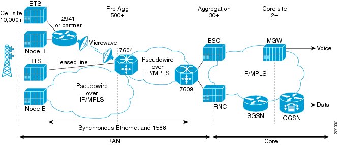
Radio access network (RAN) transport manages the backhaul traffic (both voice and data) from the cell site base transceiver stations (BTSs) to aggregation nodes and to base station controllers (BSCs), between BSCs, and between the BSC and an associated mobile switching center (MSC). Figure 4-1 shows an example RAN backhaul topology.

Figure 4-1 Example RAN Backhaul Topology

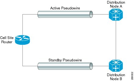
Figure 4-2 is an abstracted topology view that is used in this chapter when discussing how to configure RAN backhaul services in the Prime Provisioning GUI.

Figure 4-2 Abstracted RAN Backhual Topology

Prime Provisioning uses Internet Protocol (IP) to transport backhaul traffic in RANs. You use Ethernet Virtual Circuit (EVC) policies and service requests in Prime Provisioning to provision the following services to support RAN backhaul traffic management:

Circuit Emulation Time Delay Multiple Access (CEM TDM)

Pseudowire provisioning of Asynchronous Transfer Mode (ATM)

In addition, the EVC service requests use CEM and pseudowire class objects to bundle common attributes for resuse on every node where the service is provisioned.

The basic workflow for configuring and managing RAN backhaul services in Prime Provisioning, involves the following tasks:

1. Verify prerequisites and preform necessary setup tasks.

2. Create CEM and/or pseudowire classes to be used in RAN backhaul policies and service requests.

3. Create the CEM TDM or ATM policy.

4. Create template(s) for use in the CEM TDM or ATM service request.

5. Create the CEM TDM or ATM service request.

6. Deploy the service request to the device(s) on the network.

The chapter is organized into two sections, one for CEM TDM services and one for ATM services. The above workflow tasks are documented in each of these sections.

Prerequisites

This section covers prerequisites and limitations you should be aware of before configuring RAN backhaul services in Prime Provisioning.

To create CEM TDM policies and service requests, you must first define the service-related elements Prime Provisioning, such as target devices and network links. Normally, you create these elements once. For some coverage of these tasks, see Setting Up the Prime Provisioning Services. Also see other chapters of this guide for how to perform basic infrastructure set up and discovery tasks. The information in the following chapters assumes you have already performed these preliminary tasks.

Chapter 4 "Working with CEM TDM Services (RAN Backhaul)"

Chapter 5 "Working with ATM Services (RAN Backhaul)"

Sample Configlets for RAN Backhaul Services

This section provides sample configlets for RAN backhaul service provisioning in Prime Provisioning. It contains the following subsections:

Overview

CEM TDM using SAToP PW3

CEM TDM using CESoPSN

ATM/IMA PVP Service

ATM/IMA VCC Service

Overview

The configlets provided in this section show the CLIs generated by Prime Provisioning for particular services and features. Each configlet example provides the following information:

Service

Feature

Devices configuration (network role, hardware platform, relationship of the devices and other relevant information)

Sample configlets for each device in the configuration

Comments


Note The configlets generated by Prime Provisioning are only the delta between what needs to be provisioned and what currently exists on the device. This means that if a relevant CLI is already on the device, it does not show up in the associated configlet.


Note The CLIs shown in bold are the most relevant commands.


CEM TDM using SAToP PW3

Configuration

Service: RAN Backhaul.

Feature: This sections contains sample configlets that would be generated for CEM TDM SAToP PW3 service on a cell site router and two distribution nodes (A and B).

Device configuration:

The cell site router is an MWR 2941-DC router with an IOS image.

Controller: E1 0/0

Interface(s): CEM 0/0

Distribution node A is a 760X series device with IOS image.

Contoller: SONET 3/0/0

Interface(s): CEM 3/0/0

Distribution node B is a 760X series device with IOS image.

Contoller: SONET 3/0/0

Interface(s): CEM 3/0/0

Configlets

Cell Site Router

pseudowire-class c76a3-1

encapsulation mpls

!

pseudowire-class c76a3-2

encapsulation mpls

!

controller E1 0/0

clock source internal

cem-group 0 unframed

!

interface CEM0/0

no ip address

cem 0

xconnect 10.0.0.1 2090102001 pw-class c76a3-1

backup peer 10.0.0.4 2090403001 pw-class c76a3-2


Distribution Node A
Distribution Node B

pseudowire-class c76a3-1

encapsulation mpls

preferred-path interface Tunnel211

!

controller SONET 3/0/0

ais-shut

framing sdh

clock source line

aug mapping au-4

!

au-4 1 tug-3 2

mode c-12

tug-2 1 e1 1 description m29a2-3(CEM0/0)

tug-2 1 e1 1 cem-group 100 unframed

!

interface CEM3/0/0

no ip address

cem 100

xconnect 10.0.0.1 2090102001 pw-class c76a3-1 sequencing both

pseudowire-class c76a3-2

encapsulation mpls

preferred-path interface Tunnel340

!

controller SONET 3/0/0

ais-shut

framing sdh

clock source line

aug mapping au-4

!

au-4 1 tug-3 2

mode c-12

tug-2 1 e1 1 description m29a2-3(CEM0/0)

tug-2 1 e1 1 cem-group 100 unframed

tug-2 1 e1 1 framing unframed

!

interface CEM3/0/0

cem 100

xconnect 10.0.0.4 2090403001 pw-class c76a3-2 sequencing both


Comments

None.

CEM TDM using CESoPSN

Configuration

Service: RAN Backhaul.

Feature: This sections contains sample configlets that would be generated for CEM TDM CESoPSN service on a cell site router and two distribution nodes (A and B).

Device configuration:

The cell site router is an MWR 2941-DC router with an IOS image.

Contoller: E1 0/4

Interface(s): CEM 0/4

Distribution node A is a 760X series device with IOS image.

Contoller: SONET 3/0/0

Interface(s): CEM 3/0/0

Distribution node B is a 760X series device with IOS image.

Contoller: SONET 3/0/0

Interface(s): CEM 3/0/0

Configlets

Cell Site Router

pseudowire-class c76a3-1

encapsulation mpls

!

pseudowire-class c76a3-2

encapsulation mpls

!

controller E1 0/4

clock source internal

cem-group 0 timeslots 1-7

!

interface CEM0/4

cem 0

xconnect 10.0.0.1 3090102001 pw-class c76a3-1

backup peer 10.0.0.4 3090403001 pw-class c76a3-2


Distribution Node A
Distribution Node B

pseudowire-class c76a3-1

encapsulation mpls

preferred-path interface Tunnel211

!

controller SONET 3/0/0

ais-shut

framing sdh

clock source line

aug mapping au-4

!

au-4 1 tug-3 2

mode c-12

tug-2 2 e1 2 description m29a2-3(CEM0/4 cem 0)

tug-2 2 e1 2 cem-group 104 timeslots 1-7

!

interface CEM3/0/0

cem 104

xconnect 10.0.0.1 3090102001 pw-class c76a3-1 sequencing both

pseudowire-class c76a3-2

encapsulation mpls

preferred-path interface Tunnel340

!

controller SONET 3/0/0

ais-shut

framing sdh

clock source line

aug mapping au-4

!

au-4 1 tug-3 2

mode c-12

tug-2 2 e1 2 description m29a2-3(CEM0/4 cem 0)

tug-2 2 e1 2 cem-group 104 timeslots 1-7

!

interface CEM3/0/0

cem 104

xconnect 10.0.0.4 3090403001 pw-class c76a3-2 sequencing both


Comments

None.

ATM/IMA PVP Service

Configuration

Service: RAN Backhaul.

Feature: This sections contains sample configlets that would be generated for ATM PVP service on a cell site router and two distribution nodes.

Device configuration:

The cell site router is an MWR 2941-DC router with an IOS image.

Contoller(s): E1 0/12, E1 0/13

Interface(s): ATM0/IMA2

Distribution node A is a 760X series device with IOS image.

Interface(s): ATM 3/1/1

Distribution node B is a 760X series device with IOS image.

Interface(s): ATM 3/1/1

Configlets

Cell Site Router

pseudowire-class c76a3-1

encapsulation mpls

!

pseudowire-class c76a3-2

encapsulation mpls

!

controller E1 0/12

framing NO-CRC4

clock source internal

ima-group 2 scrambling-payload

!

controller E1 0/13

framing NO-CRC4

clock source internal

ima-group 2 scrambling-payload

!

interface ATM0/IMA2

no ip address

ima version 1.0

ima group-id 2

atm mcpt-timers 1000 5000 10000

atm pvp 9 l2transport

cell-packing 28 mcpt-timer 3

xconnect 10.0.0.1 4090102003 pw-class c76a3-1

backup peer 10.0.0.4 4090403003 pw-class c76a3-2

no atm ilmi-keepalive


Distribution Node Z
Distribution Node Z Backup

pseudowire-class c76a3-1

encapsulation mpls

preferred-path interface Tunnel211

!

interface ATM3/1/1

no ip address

atm mcpt-timers 1000 5000 10000

atm pvp 9 l2transport

cell-packing 28 mcpt-timer 3

xconnect 10.0.0.1 4090102003 pw-class c76a3-1

no atm enable-ilmi-trap

pseudowire-class c76a3-2

encapsulation mpls

preferred-path interface Tunnel340

!

interface ATM3/1/1

no ip address

atm mcpt-timers 1000 5000 10000

atm pvp 9 l2transport

cell-packing 28 mcpt-timer 3

xconnect 10.0.0.4 4090403003 pw-class c76a3-2

no atm enable-ilmi-trap


Comments

None.

ATM/IMA VCC Service

Configuration

Service: RAN Backhaul.

Feature: This sections contains sample configlets that would be generated for ATM VCC service on a cell site router and two distribution nodes.

Device configuration:

The cell site router is an MWR 2941-DC router with an IOS image.

Contoller(s): E1 0/8, E1 0/9

Interface(s): ATM0/IMA0, ATM0/ IMA0

Distribution node A is a 760X series device with IOS image.

Interface(s): ATM 3/1/0

Distribution node B is a 760X series device with IOS image.

Interface(s): ATM 3/1/0

Configlets

Cell Site Router

pseudowire-class c76a3-1

encapsulation mpls

!

pseudowire-class c76a3-2

encapsulation mpls

!

controller E1 0/8

framing NO-CRC4

clock source internal

ima-group 0 scrambling-payload

!

controller E1 0/9

framing NO-CRC4

clock source internal

ima-group 0 scrambling-payload

!

interface ATM0/IMA0

ima version 1.0

ima group-id 0

atm mcpt-timers 1000 5000 10000

!

interface ATM0/IMA0.1 point-to-point

snmp trap link-status

pvc 9/34 l2transport

cbr 255

encapsulation aal0

cell-packing 28 mcpt-timer 3

xconnect 10.0.0.1 4090102001 pw-class c76a3-1

backup peer 10.0.0.4 4090403001 pw-class c76a3-2


Distribution Node Z
Distribution Node Z Backup

pseudowire-class c76a3-1

encapsulation mpls

preferred-path interface Tunnel211

!

interface ATM3/1/0

atm mcpt-timers 1000 5000 10000

!

interface ATM3/1/0.9001 point-to-point

description m29a2-3 - ATM0/IMA0

no atm enable-ilmi-trap

pvc 9/34 l2transport

cell-packing 28 mcpt-timer 3

encapsulation aal0

xconnect 10.0.0.1 4090102001 pw-class c76a3-1

pseudowire-class c76a3-2

encapsulation mpls

preferred-path interface Tunnel340

!

interface ATM3/1/0

atm mcpt-timers 1000 5000 10000

!

interface ATM3/1/0.9001 point-to-point

description m29a2-3 - ATM0/IMA0

no atm enable-ilmi-trap

pvc 9/34 l2transport

cell-packing 28 mcpt-timer 3

encapsulation aal0

xconnect 10.0.0.4 4090403001 pw-class c76a3-2


Comments

None.