-
Cisco Prime Provisioning User Guide, 6.3
-
About The Book
-
Using the Prime Provisioning Graphical User Interface
-
Setting Up Prime Provisioning Services
-
Managing Carrier Ethernet and L2VPN Services
-
Managing RAN Backhaul Services
-
Managing MPLS VPN Services
-
Managing MPLS Transport Profile Services
-
Managing MPLS Traffic Engineering Services
-
Managing Service Requests
-
Managing Templates and Data Files
-
Monitoring
-
Performing Diagnostics
-
Using the Topology Tool
-
Using Inventory Manager
-
Cisco Configuration Engine Server
-
XML Reference
-
Terminating an Access Ring on Two N-PEs
-
Repository Views
-
Inventory - Discovery
-
Adding Additional Information to Services
-
 Feedback
Table Of Contents
Managing MPLS Transport Profile Services
MPLS-TP Setup and Installation
Other MPLS-TP Preconfiguration Requirements
Creating an MPLS-TP Discovery Task
Verifying the MPLS-TP Discovery Results
Verifying Links, Pools, and MPLS-TP Global and Router IDs
Creating an MPLS-TP Service Request
Running MPLS-TP Functional Audit
Managing MPLS-TP Topology Changes
MPLS-TP Working Tunnel Configlet (IOS)
MPLS-TP Working Tunnel Configlet (IOS-XR)
Managing MPLS Transport Profile Services
This chapter describes the tasks required to get started using Prime Provisioning, Multiprotocol Label Switching (MPLS) Transport Profile (TP) services.
This section covers the following topics:
•
Prerequisites and Limitations
•
Introduction
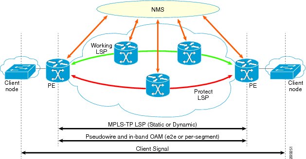
MPLS-TP is a transport service (managed by Prime Provisioning) for a dynamic MPLS core.
In the current implementation of MPLS-TP, an MPLS-TP tunnel can be provisioned between two arbitrary nodes in an MPLS-TP enabled network. The provisioned tunnel can have one or two paths, a working and an optional protect label-switched path (LSP). The normal use case is for Prime Provisioning to automatically calculate the working and protect paths using a path selection algorithm that chooses MPLS-TP enabled links based on shortest path, and to provision the tunnel on the endpoints and all nodes traversed by the tunnel.
Figure 6-1 An MPLS-TP Enabled Network
Prerequisites and Limitations
The current release of Prime Provisioning involves certain prerequisites and limitations, which are described in the Cisco Prime Provisioning 6.3 Installation Guide, including general system recommendations.
Note that Internet Explorer 8 (IE8) will not show the calculated path graphically (as described in Creating an MPLS-TP Service Request) as IE8 offers no support for SVG display. Until IE9 is supported, a textual summary of the path can be used to review the path in IE8.
Changes performed to an operational device sometimes take time to reflect on Prime Network.
Polling is performed by Prime N every 15 minutes (at least). In the duration of 1 to 15 minutes, polling is performed many times. Each poll collects different data (tunnels, labels, links, etc). Since all the information is not collected in a single poll, the time taken to reflect tunnel update, label update, links update varies in Prime N.
For supported device and OS information, refer to Cisco Prime Provisioning 6.3 Supported Devices.
Preconfiguration Process
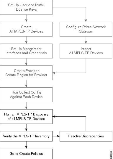
The preconfiguration process sets up key parameters that enable the system to collect MPLS-TP network information and subsequently deploy MPLS-TP configurations on the chosen network.
The different steps in the preconfiguration process are provided in Figure 6-2.
Figure 6-2 Preconfiguration Process
Before commencing the preconfiguration process, MPLS-TP needs to be enabled on the network devices by making sure that the IP addresses used as devices' MPLS-TP IDs are accessible from the management station (this step is not supported by MPLS-TP). This is described in Other MPLS-TP Preconfiguration Requirements.
Setting up new user and installing license keys is described in Cisco Prime Provisioning Administrator's Guide 6.3 and the other steps are covered in Setting Up Devices and Device Groups and the Inventory - Discovery appendix (Collect Config step).
As a result, the Prime Provisioning user will need to wait some before running MPLS-TP Discovery after a device change in Prime Network.
Note
See below for a description of specific MPLS-TP user roles.
The MPLS-TP-specific steps are as follows:
1.
2.
MPLS-TP Setup and Installation
Before setting up Prime Provisioning, the Prime Provisioning software must be installed. To do so, see the Cisco Prime Provisioning 6.3 Installation Guide.
To set up a new Prime Provisioning user, one or more users with a MPLS-TP role must be created. MPLS-TP roles are described in MPLS-TP User Roles and for step by step instructions for creating user roles, refer to Cisco Prime Provisioning Administrator's Guide 6.3.
Licensing information, including the Prime Provisioning licensing options and for the procedure needed to install licenses, refer to Cisco Prime Provisioning Administrator's Guide 6.3.
MPLS-TP User Roles
Prime Provisioning currently supports two MPLS-TP roles, the MPLS-TPRole and MPLS-TPServiceOpRole. These 2 user roles behave similarly to the other roles in Prime Provisioning, for example the MPLSRole and the MPLSServiceOpRole found in MPLS.
They have the following permissions:
–
–
For an explanation of how to work with roles, refer to Cisco Prime Provisioning Administrator's Guide 6.3.
Other MPLS-TP Preconfiguration Requirements
Prior to performing MPLS-TP provisioning, perform the following additional configuration steps:
Step 1
•
•
•
Step 2
Step 3
•
•
Step 4
Running MPLS-TP Discovery
Prime Provisioning supports MPLS-TP discovery from IOS and IOS-XR devices when deployed together with Prime Network (or) in the IP-NGN suite. Prime Provisioning can be 'paired' with Prime Network by setting the Prime Network gateway detail in the Prime Provisioning DCPL property Inventory Import.
Prime Provisioning, in standalone mode (without Prime Network integration) supports CDP-based MPLS-TP discovery from IOS devices but this is deprecated.
As a prerequisite for running MPLS-TP discovery, all devices must be present and a Collect Config task must be run (see the Inventory - Discovery appendix, Collect Config step). Set the Prime Network Gateway details in the Prime Provisioning DCPL properties, refer to Cisco Prime Provisioning Administrator's Guide 6.3 for details on setting the DCPL properties.
MPLS-TP enabled devices should be added or created on Prime Provisioning Inventory by:
•
or
•
The MPLS-TP network is discovered using the MPLS-TP Discovery task. This populates the repository with the network topology in an automated way. The necessary steps are described in this section.
Note
The MPLS-TP discovery process discovers the following from the live network:
•
•
•
•
•
•
Where possible, the discovery process will try to keep the repository consistent with the network, for example delete links which have been removed. In cases where this is not possible, for example if a link is in use, a log message will be recorded.
This section includes the following:
•
•
•
Creating an MPLS-TP Discovery Task
To create a MPLS-TP Discovery task on the MPLS-TP network, use the following steps:
Step 1
The Task Manager window appears.
Step 2
The Create Task window appears.
Step 3
The MPLS-TP Discovery window appears.
Step 4
Step 5
The discovery process begins.
Step 6
Operate > Task Logs.
To run the MPLS-TP Discovery task immediately after the device creation navigate to:
Inventory > Devices > Create > Cisco Device.
Select the MPLS-TP check box in Create Cisco Router window.
Links and resource pools should now be visible in the MPLS-TP Details window, which is accessible from the Inventory > Devices > MPLS-TP Details page.
Verifying the MPLS-TP Discovery Results
After running MPLS-TP Discovery, you can see the result in various ways.
Viewing Logs
Once the MPLS-TP Discovery task is completed, you can view the log that is generated. This summary log will list any changes that have occurred in the MPLS-TP network. Discovery updates the logs with affected SR's in cases where the links in working or protect LSP no longer exist or have been changed. This could be as a result of node insertion/removal or simply changing a link number.
To view the log, select the relevant task in Task Manager and click Logs.
Verifying Links, Pools, and MPLS-TP Global and Router IDs
To verify the status of links and pools, go to the MPLS-TP Details page at Inventory > Devices > MPLS-TP Details.
The MPLS-TP global and router IDs for a particular device can be verified by going to Inventory > Devices > Edit.
MPLS-TP Label Sync
MPLS-TP Label Sync task is to update the labels information. MPLS-TP Labels can be out of synch due to manual provisioning. Hence, it is recommended to update the label information alone rather than the entire MPLS-TP topology information often.
Similar to MPLS-TP Discovery, MPLS-TP Label Synch task can be performed from:
•
•
•
Creating an MPLS-TP Policy
An MPLS-TP policy is needed to successfully create and deploy a service request. It serves as a template for the settings that are needed on the device.
To create an MPLS-TP policy, use the following steps:
Step 1
a.
In the Policy Manager window, click Create.
b.
In either case, a Policy Type drop-down appears.
Step 2
The Policy Information accordion opens.
Step 3
Enter Policy Name and optionally a Description. Policy Name is the only field that is mandatory in the Policy Editor.
Step 4
The Policy Information accordion closes and the next accordion opens.
Step 5
Set how each of the attributes will be displayed within the Service Request Editor window using the drop-down next to each field:
•
•
•
Make sure to select Editable for any fields that you want to be able to edit in the Service Request Editor.
Use the State field to indicate whether the tunnel should be provisioned with the shutdown command or not.
For path protection, keep the Protection box selected to have Prime Provisioning autogenerate an alternate protective path for the new tunnel.
For the Diversity Options drop-down menu, choose one of the following options:
•
•
•
Step 6
As in the previous accordion, remember to specify which fields should be Editable, Visible, and Hidden in the Service Request Editor.
Complete the fields as needed, using the drop-downs to select source and destination nodes and BFD templates.
Note
Select the required BFD templates from a list of available BFD templates on the source and destination devices respectively. A valid BFD template name is max. 31 characters long.
For an explanation of global ID and router ID, see Global ID and Router ID.
Step 7
The new policy appears in the list of tunnels in the Policy Manager.
Global ID and Router ID
Global ID and router ID are used to identify devices within the MPLS-TP network so they can be discovered and managed.
If you as a user decide to specify the router ID and global ID, those values will be used for tunnel creation. If they are not specified, the router ID and global ID configured on the device itself are used.
Every MPLS-TP tunnel and LSP has a unique ID formed by the concatenation of the Global ID, Router ID, Tunnel ID, and LSP ID of both ends of the tunnel. This ID is configured at every endpoint and midpoint of the tunnel. The Global ID and router ID are normally configured globally on a router but it is possible to override these values for specific tunnels. Prime Provisioning is aware of the globally configured IDs and uses them when configuring tunnels but also allows you to override these values as needed.
Global ID
Every MPLS-TP enabled node can have an MPLS-TP global ID configured within the global configuration. If the Global ID is set at the MPLS-TP global configuration level, it will be used as the default global ID for all endpoint and midpoint configuration. If not configured, a global ID of 0 is used for configured tunnels unless a different value is explicitly specified within the tunnel configuration itself.
The MPLS-TP global ID is retrieved from a device via MPLS-TP discovery.
Router ID
To be MPLS-TP enabled, a device must have a router ID.
If neither the MPLS-TP router ID nor the MPLS-TP global ID can be retrieved from the device, this is logged in the corresponding MPLS-TP Discovery task log file and all remaining MPLS-TP Discovery steps are halted for this device. The device in question is flagged as being MPLS-TP Disabled.
Creating an MPLS-TP Service Request
An MPLS-TP service request needs to be created to deploy a service request. It is assumed that at least one MPLS-TP policy is available. If not, see Creating an MPLS-TP Policy.
To create an MPLS-TP service request, use the following steps:
Step 1
a.
b.
The Service Request Editor window appears.
Next to the Policy field, click the down-arrow to open the policy picker.
Step 2
The Service Request Editor opens. In this editor,
Step 3
Step 4
To set the Diversity Options, see Creating an MPLS-TP Policy for an explanation.
Step 5
In this accordion, both source device, destination device, and BFD information is mandatory.
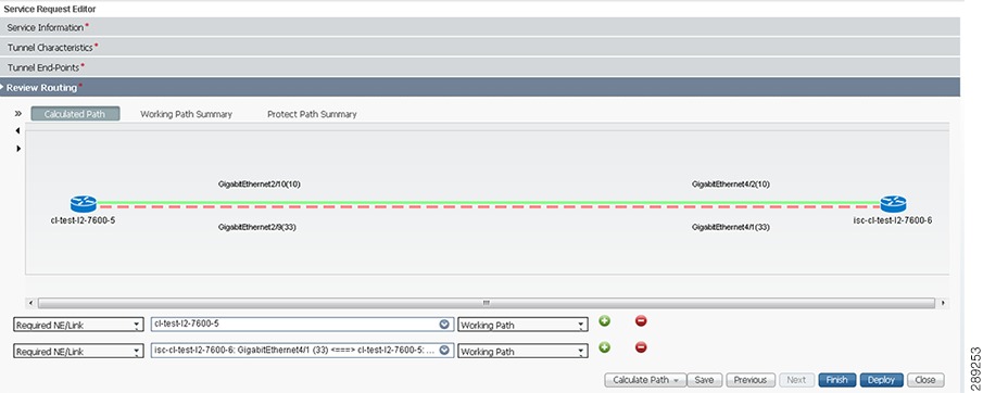
Step 6
Working path—Green solid line
Protect Link—Red dotted line
For an example of an MPLS-TP routing diagram, see Figure 6-3.
Figure 6-3 MPLS-TP Routing Diagram
•
•
•
–
–
For more information about path constraints, see Working with Path Constraints.
Step 7
Step 8
The Service Request Manager window opens.
For information about the Service Request Manager elements and operations, see Chapter 8 "Managing Service Requests."
Guidelines for working with path constraints are provided in Working with Path Constraints.
An MPLS-TP service request that is in the DRAFT state can be modified. If a DRAFT MPLS-TP service request is modified, the new values will replace the previously saved values.
A service request in DRAFT state is marked by a white/orange work cone in the Service Request Manager.
Working with Path Constraints
Path constraints can be added to control the tunnel path when a service request is created or modified as shown in the procedure in Step 6 in the create procedure.
There are two ways to add path constraints:
•
•
Note
Running Config Audit
A config audit task can be run against an MPLS-TP service requests to check that the configuration rolled onto a device by a particular service request is still present as expected.
To create a MPLS-TP Config Audit task, use the following steps:
Step 1
Step 2
Step 3
The service request selection window appears.
Step 4
Step 5
If successful, this adds the task to the list of created tasks in the Tasks window.
To view the task logs for the created tasks, in Task Manager select the created task and click Logs.
Running MPLS-TP Functional Audit
In an MPLS-TP Functional Audit, information is retrieved from source and destination endpoints to provide tunnel audit information.
This task only performs functional audit on service requests, which are not in one of the following states:
•
•
•
•
•
For more information on working with service requests, see Chapter 8 "Managing Service Requests."
To create a MPLS-TP Functional Audit task, use the following steps:
Step 1
Step 2
Step 3
The service request selection window appears.
Step 4
Step 5
If successful, this adds the task to the list of created tasks in the Tasks window.
To view the task logs for the created tasks, in Task Manager select the created task and click Logs.
Managing MPLS-TP Topology Changes
When a topology changes due to node insertion/removal, the MPLS-TP discovery has the ability to:
•
•
•
•
•
–
–
•
–
–
–
–
•
–
–
•
•
•
•
Deploying an MPLS-TP Tunnel
The final step required to provision an MPLS-TP service request is the deploy the service request. This pushes the service request and the associated configuration updates to the network.
Note
The deploy functionality is the same as for other Prime Provisioning services. For instructions on how to deploy an MPLS-TP service request, see Deploying Service Requests.
Decommissioning
MPLS-TP service request configurations can be removed from the network using the decommissioning functionality within the Service Request Manager. Decommissioning will cause the previously deployed configurations to be removed from all tunnel endpoint and mid-point devices within the MPLS-TP tunnel path.
To decommission one or more service requests, see Chapter 8 "Managing Service Requests."
Sample Configlets
The configlets included in this section show the CLIs generated by Prime Provisioning for particular services and features. Each configlet example provides the following information:
•
•
•
•
•
All examples in this section assume the presence of an MPLS-TP core.
Note
This section provides sample configlets for MPLS-TP service provisioning in Prime Provisioning.
It includes the following section:
•
•
MPLS-TP Working Tunnel Configlet (IOS)
Configuration
•
•
Configlets
MPLS-TP Working Tunnel Configlet (IOS-XR)
Configuration
•
•
Configlets