-
Cisco IP Solution Center Infrastructure Reference, 5.2
-
Index
-
About This Guide
-
Getting Started
-
WatchDog Commands
-
Service Inventory - Inventory and Connection Manager
-
Service Inventory - Discovery
-
Service Inventory - Device Console
-
Service Design
-
Monitoring
-
Diagnostics
-
Administration
-
Cisco CNS IE2100 Appliances
-
ISC XML Reference
-
Property Settings
-
Template Usage
-
Glossary
-
 Feedback
Table Of Contents
View Templates Tree and Data Pane
Summary of Repository Variables
Importing and Exporting Templates
Service Design
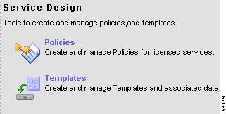
From the Home window of Cisco IP Solution Center (ISC), which you receive upon logging in, click the Service Design tab and you receive a window as shown in Figure 6-1, "Service Design Selections."
Figure 6-1 Service Design Selections
Next you can choose the following selections:
•
Policies—Create and manage Policies for licensed services.
•
Policies
Policies is explained in each of the ISC User Guides for each of the applicable licensed services.
Templates
Templates provide a means to deploy commands and configurations not normally supported by ISC to a device. Templates are written in the Velocity Template Language (VTL) and are generally comprised of IOS and IOS XR device CLI configurations.
Templates support the browsing, creation, and deletion of Template Folders, Templates, and Data Files and it supports the viewing of Template-generated configurations. This is applicable to both IOS and IOS XR. For IOS XR devices the configlet generated from template datafiles are CLI commands, not XML commands.
The configuration created from the template and data file can be downloaded to devices. When creating a Service Request, you can select from the list of templates and data files and associate them with the Service Request. At Deploy time, the template and data file are instantiated and the configuration is appended or prepended to the configlet generated by ISC. Another method is to use the Device Console feature to download templates independent of Service Requests, as explained in the "Download Template" section on page 5-3.
ISC provides a way to integrate a template with ISC configlets.
For a given customer edge router and/or provider edge router, you specify the following:
•
•
•
•
The template data files are tightly linked with the corresponding template (a data file cannot be linked to more than one template). You can use a data file and its associated template to create a template configuration file. The template configuration file is merged with (either appended or prepended to) the ISC configlet. ISC downloads the combined ISC configlet and template configuration file to the edge device router.
•
•
Template commands are treated independently from those associated with a service creation (Multi Protocol Label Switching (MPLS), Layer 2 Virtual Private Network (L2VPN), Virtual Private LAN Service (VPLS), Traffic Engineering (TE), and so on). Consequently, template commands must be removed separately from the device(s) during a service decommission. To remove prior template commands, a separate template is needed during a decommission process. Decommissioning a service request does not automatically remove the original template commands. A separate negate template needs to be added to the decommission process and the original templates must be removed. The negate template must contain the necessary NO commands to successfully remove any unwanted IOS commands added by the original template.
Note
To use Templates, follow these steps:
Step 1
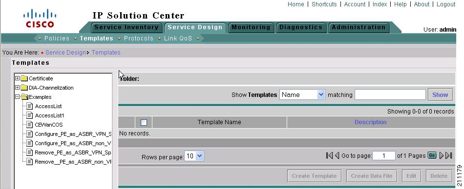
Figure 6-2 Templates
Template examples are shown in the left column. A complete list of template examples is specified in the Template Examples. A complete list of Repository variables is shown in the "Summary of Repository Variables" section. An explanation of a tool for importing and exporting templates into and from an ISC database is given in the "Importing and Exporting Templates" section.
Step 2
•
•
•
View Templates Tree and Data Pane
When you choose Service Design > Templates, you receive a window as shown in Figure 6-3, "Tree and Data Pane Structure."
The Templates tree is in the left column. You can continue clicking the + sign next to each created folder and subfolder until you get to the last level of information. The last possible level is the template name. Data file information is not kept in the tree.
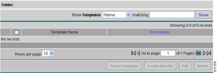
The right section of the window is the data pane. The name of the folder or template is in the upper-left corner. When you check the check box next to the template or data file information, the Create Template, Create Data File, Edit, or Delete buttons are enabled as described in the following sections.
When there are many templates in a folder or many data files in a template, the Show Templates matching or Show Data Files matching filter in the upper right-hand corner of the data pane can be very useful. For example, you can click the drop-down list for Show Templates or Show Data Files and choose to match (matches are case-sensitive) the Name or Description and then in the matching box you can choose to work with templates or data files, respectively, that start with abc. In this case, enter abc* in the field and then click the Show button. Only the templates or data files, respectively, that start with abc appear. For more information about filters, see Filters, page 1-7.
Note
Note
You can also View configurations when the table displays data files.
Figure 6-3 Tree and Data Pane Structure
Create Folders and Subfolders
To create a new folder or subfolder, follow these steps:
Step 1
Step 2
Note
Step 3
Copying Folders or Subfolders
To copy a folder or subfolder and paste it into another folder or subfolder, follow these steps:
Step 1
Step 2
You will see the new folder or subfolder and all its content in the selected location. You can edit from there.
Create Template
You can either create a new template in an existing folder or you can create a new folder first and then create the template. To create a new folder, see the section "Create Folders and Subfolders".
To create a new template, follow these steps:
Step 1
Step 2
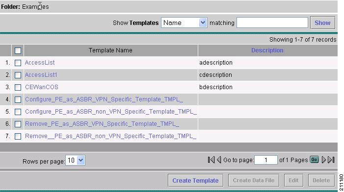
A window appears as shown in Figure 6-4, "Folder with Existing Templates."
Figure 6-4 Folder with Existing Templates
Step 3
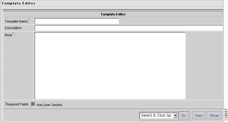
Step 4
Figure 6-5 Template Editor
Step 5
•
•
•
Note
Note
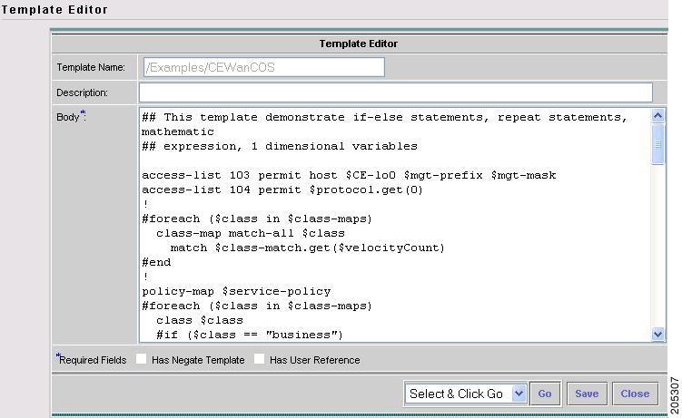
An example template is shown in Figure 6-6, "Example Template."
Figure 6-6 Example Template
Step 6
Negate Template
To remove a configuration created from a template or datafile, you must apply Negate to the existing service. The negate template is saved as <TemplateName>.Negate in the same folder as the original template. When a template is removed, the negate template is also deleted. You can also delete the negate template separately. Datafiles can be associated for the negate template.
When a template is associated in a service Policy and Service Request, the negate template is automatically associated (see the Cisco IP Solution L2VPN and Center Carrier Ethernet User Guide, 5.2 and the Cisco IP Solution Center MPLS VPN User Guide, 5.2).
During decommissioning, a negate template is used for deployment. If you change a template, the negate template automatically changes to the negate template of the newly selected template.
Do the following after clicking the Select & Click Go drop-down list in Step 6 of the "Create Template" section:
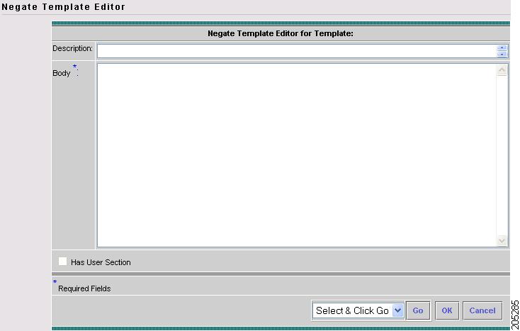
Step 1
Figure 6-7 Negate Template Editor
Step 2
Step 3
User Reference
You can keep information about this template by using User Reference.
Do the following after clicking the Select & Click Go drop-down list in Step 6 of the "Create Template" section:
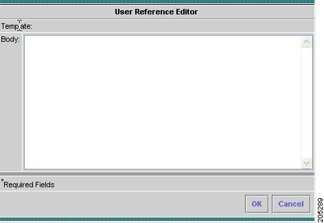
Step 1
Figure 6-8 User Reference Editor
Step 2
Step 3
Optional Attributes
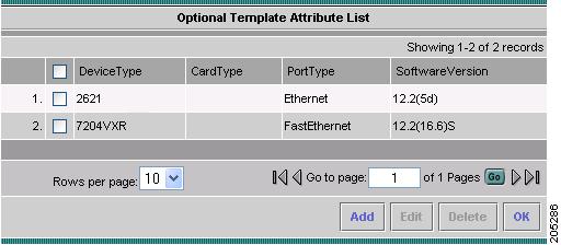
When you choose Optional Attributes, you can view the predefined Device Type, Card Type, Port Type, and Software Version (IOS and IOS XR) populated from the ISC repository. When no attribute value is provided for any of the four categories, the attribute is applicable for all in that type. For example, if the drop-down list for Port Type has no choices, the attribute value is applicable for all Port Types. Each combination of attributes should match. Each combination of attributes is called an attribute set, and templates can have multiple attributes, for example, a template can be applicable for the 7600 series and the 3500 series.
Do the following after clicking the Select & Click Go drop-down list in Step 6 of the "Create Template" section:
Step 1
Figure 6-9 Optional Template Attribute List
Step 2
Step 3
•
•
•
•
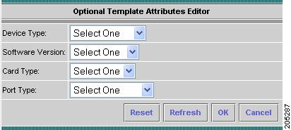
Step 4
Note
Figure 6-10 Optional Template Attributes Editor
Step 5
Note
Step 6
•
•
Note
Note
•
•
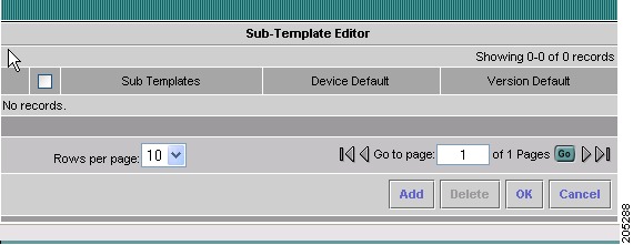
Sub-Template
A template using other templates is called a super-template. The template being used is called the sub-template. The super-template instantiates all required sub-templates by passing values for the variables in the sub-template. After instantiation, the super-template puts the sub-template generated configlet into the super-template.
Do the following after clicking the Select & Click Go drop-down list in Step 6 of the "Create Template" section:
Step 1
Figure 6-11 Sub-Template Editor
Step 2
•
•
•
•
Step 3
•
•
•
•
•
Step 4
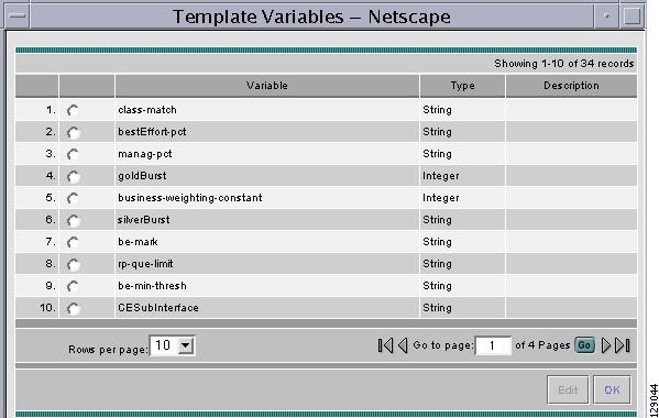
Variables
Do the following after clicking the Select & Click Go drop-down list in Step 6 of the "Create Template" section:
Step 1
Figure 6-12 Template Variables
Step 2
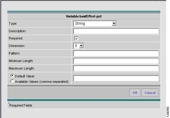
You receive a window as shown in Figure 6-13, "Variable Definition—Type String."
Figure 6-13 Variable Definition—Type String
Step 3
•
•
•
•
•
Step 4
•
•
•
•
•
•
•
•
After you enter all the data, click OK to accept this information for the specified variable; continue editing all variables you want to change in this same way, then click OK in a window such as Figure 6-12, which now includes these updated variables; click Save and then Close or click Close and when asked, agree to Save for a window such as Figure 6-5. Create a Data File is shown in the "Create Data File" section, Edit is shown in the "Edit" section, and Delete is shown in the "Delete" section.
Step 5
•
•
•
•
•
•
•
After you enter all the data, click OK to accept this information for the specified variable; continue editing all variables you want to change in this same way, then click OK in a window such as Figure 6-12, which now includes these updated variables; click Save and then Close or click Close and when asked, agree to Save for a window such as Figure 6-5. Create a Data File is shown in the "Create Data File" section, Edit is shown in the "Edit" section, and Delete is shown in the "Delete" section.
Figure 6-14 Variable Definition—Type Integer
Step 6
•
•
•
•
•
•
•
After you enter all the data, click OK to accept this information for the specified variable; continue editing all variables you want to change in this same way, then click OK in a window such as Figure 6-12, which now includes these updated variables; click Save and then Close or click Close and when asked, agree to Save for a window such as Figure 6-5. Create a Data File is shown in the "Create Data File" section, Edit is shown in the "Edit" section, and Delete is shown in the "Delete" section.
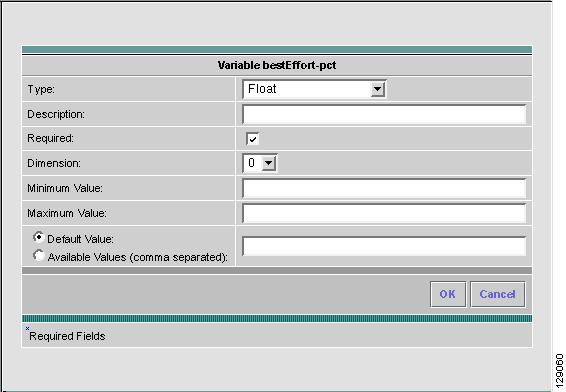
Figure 6-15 Variable Definition—Type Float
Step 7
•
•
•
•
•
•
•
After you enter all the data, click OK to accept this information for the specified variable; continue editing all variables you want to change in this same way, then click OK in a window such as Figure 6-12, which now includes these updated variables; click Save and then Close or click Close and when asked, agree to Save for a window such as Figure 6-5. Create a Data File is shown in the "Create Data File" section, Edit is shown in the "Edit" section, and Delete is shown in the "Delete" section.
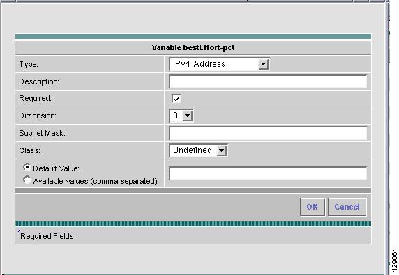
Figure 6-16 Variable Definition—Type IPv4
Step 8
•
•
•
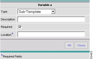
The variable varName is defined as the subtemplate type (by selecting Variables and clicking Go). The Sub-Template defined earlier is called and you must provide the subtemplate path. The syntax is as follows:
$<varName>.callWithDatafile(<DatafileName>)
After you enter all the data, click OK to accept this information for the specified variable; continue editing all variables you want to change in this same way, then click OK in a window such as Figure 6-17, which now includes these updated variables; click Save and then Close or click Close and when asked, agree to Save for a window such as Figure 6-5. Create a Data File is shown in the "Create Data File" section, Edit is shown in the "Edit" section, and Delete is shown in the "Delete" section.
Figure 6-17 Variable Definition—Type Sub-Template
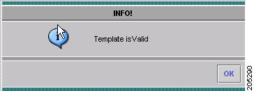
Validate
To validate the information you entered in Figure 6-5 (see Step 5), do the following after clicking the Select & Click Go drop-down list in Step 6 of the "Create Template" section:
Step 1
Step 2
Figure 6-18 Validation Information
Copying Templates
To copy a user-created template and paste it into another folder, follow these steps:
Step 1
Step 2
Step 3
Deleting Templates
To delete a template from a folder, choose a template and then right-click and you receive the opportunity to delete. Click Delete.
Create Data File
You can create a new data file from an existing template. If the template you want is not available, go to the "Create Template" section.
To create a data file, follow these steps:
Step 1
Step 2
1.
2.
Step 3
Figure 6-19 Choose Existing Template
Check the check box for the template for which you want to create a data file and click Create Data File. Then proceed to .
Otherwise, proceed to Step 4.
Step 4
Figure 6-20 Choose Existing Template, Another Way
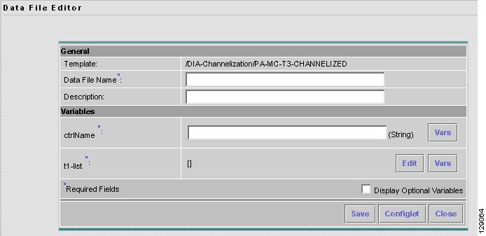
Click Create Data File. An example of a window that appears is shown in Figure 6-21, "Template Data File Editor."
Figure 6-21 Template Data File Editor
Step 5
•
•
In the example in Figure 6-21, in the Variables area, cntrlName is a string variable (Dimension defined when the template was created was 0); you can also create a one-dimensional array (Dimension defined when the template was created was 1); and t1-list is a two-dimensional array (Dimension defined when the template was created was 2).
If t1-list is a Dynamic Java Class variable, you must enter the entire Java Class package name. For example: com.cisco.isc.class_name.
Note
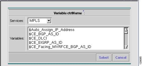
Step 6
Figure 6-22 Template Data File Editor
Click the Services drop-down list to have access to variables for:
•
•
•
•
•
Then click the entry in Variables that you want to use and click Select.
If you have a 0 dimensional entry (set as Dimension 0 when creating a template), you can only enter variables in the provided field.
Step 7
Proceed to Step 8 for information about a 1 dimensional array.
Proceed to Step 11 for information about a 2 dimensional array.
Step 8
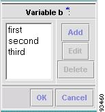
Figure 6-23 Editing a One-Dimensional Array
Step 9
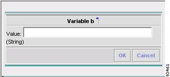
Figure 6-24 Adding a Variable
Step 10
Step 11
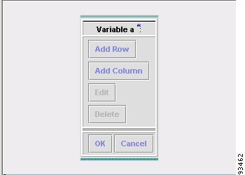
Figure 6-25 Editing a Two-Dimensional Array
Step 12
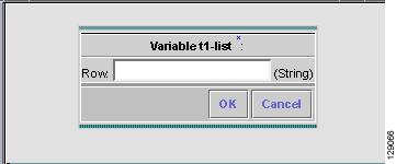
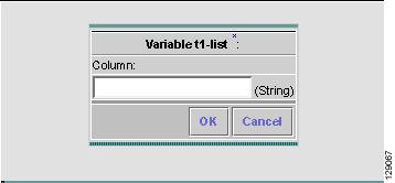
Figure 6-26 Enter Row Information
Step 13
Figure 6-27 Enter Column Information
Step 14
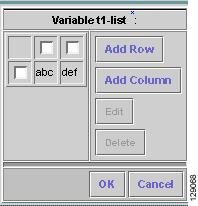
Figure 6-28 Two-Dimensional Array Results
Step 15
Step 16
Step 17
Edit
To edit a Template or Data File, follow these steps:
Step 1
Step 2
To edit a template, a window appears as shown in Figure 6-29, "Folder > Template > Edit." To edit a data file, a window appears as shown in Figure 6-30, "Folder > Template > Datafile > Edit."
Figure 6-29 Folder > Template > Edit
Figure 6-30 Folder > Template > Datafile > Edit
Step 3
Step 4
Note
Step 5
Step 6
Delete
To delete a Template or Data File, follow these steps:
Step 1
Step 2
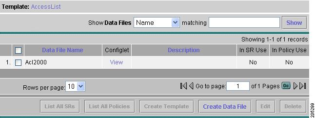
To delete a template, a window appears as shown in Figure 6-31, "Choose Existing Template > Delete." To delete a data file, a window appears as shown in Figure 6-32, "Choose Existing Data File > Delete."
Figure 6-31 Choose Existing Template > Delete
Figure 6-32 Choose Existing Data File > Delete
Step 3
Step 4
Note
Step 5
A confirmation window appears prompting you to confirm the deletion. Before deleting a datafile, make sure it is not associated with a service request, by checking that the In SR Use column is set to No. When deleting a folder or a template, make sure that none of the datafiles they contain are associated with a service request. By clicking OK, you continue the deletion, and by clicking Cancel, you cancel the deletion.
You receive an updated window as shown in Figure 6-31, "Choose Existing Template > Delete" or Figure 6-32, "Choose Existing Data File > Delete" with the deleted template or data file no longer available.
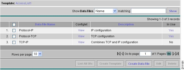
List All SRs
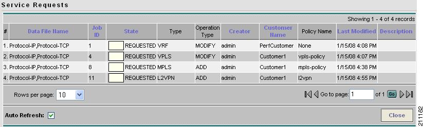
In the In SR Use column, as shown in Figure 6-32, Yes indicates that the data file is in use and No indicates that the data file is not in use. If Yes appears, you can click on it and you receive a list of all the associated service requests. If Yes appears, a List All SRs button is enabled in the bottom row. If you click the List All SRs button, all the service requests associated with the selected data file(s) appears, as shown in Figure 6-33. If No appears in the In SR Use column, the List All SRs button is disabled.
From Figure 6-33, if you click the Close button, the previous window appears.
Figure 6-33 List All SRs
Note
List All Policies
In the In Policy Use column, as shown in Figure 6-32, Yes indicates that the data file is in use and No indicates that the data file is not in use. If Yes appears, you can click on it and you receive a list of all the associated policies. If Yes appears, a List All Policies button is enabled in the bottom row. If you click the List All Policies button, all the policies associated with the selected data file(s) appears. If No appears in the In Policy Use column, the List All Policies button is disabled.
If you click the Close button for the newly created window, the previous window appears.
Note
Template Examples
In the left column, the hierarchy pane, of Service Design > Templates, as shown in Figure 6-2, "Templates," template examples appear. See Table 6-2, "Template Examples and Their Descriptions."
Summary of Repository Variables
This section contains the following tables:
•
•
•
•
•
Table 6-3 provides a summary of the L2VPN Repository variables available from ISC Templates.
Table 6-4 provides a summary of the MPLS Repository variables available from ISC Templates.
Table 6-5 provides a summary of the VPLS Repository variables available from ISC Templates.
Table 6-6 provides a summary of the VRF Repository variables available from ISC Templates.
Table 6-7 provides a summary of the FlexUNI/EVC Repository variables available from ISC Templates.
Importing and Exporting Templates
The importExportTemplateDB tool is available to import and export templates into and from an ISC database.
Note
You can import or export the complete or partial template database by specifying appropriate arguments. You can find this tool at: $ISC_HOME/bin/importExportTemplateDB.sh.
Enter the following:
importExportTemplateDB.sh <admin_user_id> <password> [<other_arguments>]
where:
<admin_user_id> is user identifier for someone with the admin role.
<password> is the password for the one with the admin role.
<other_arguments> is any combination of the following arguments separated by a space:
-nooverwrite
If you choose to use this nooverwrite argument, to prevent the overwriting of existing templates in the database, it must precede all other arguments and must be in the third position after <admin_user_id> and <password>.
Note
-exp_db <dest-dir>
Use this argument to export all templates and datafiles in the database, where <dest-dir> is the destination directory to which you want to export.-imp_db <src-dir>
Use this argument to import all the files in <src-dir> into the database, where <src-dir> is the source directory from which you want to import. The files in <src-dir> are created by the exp_db process.-exp_template_folder <src-folder-path> <dest-dir>
Use this argument to export a database template folder and its subfolders, where <src-folder-path> is the full path of the template folder to export and <dest-dir> is the directory where to place the exported files.-imp_template_folder <src-dir> <dest-folder>
Use this argument to import all files in <src-dir> into the database, where <src-dir> is the source directory to import, and <dest-folder> is the destination import template folder.-imp_template <srcfile> <dest-folder> <template-name>
Use this argument to import a template into the database, where <srcfile> is the full path of the template to import, <dest-folder> is the full path of the parent folder, and <template-name> is the template name in the database.-imp_datafile <srcfile> <dest-template> <datafile-name>
Use this argument to import a template datafile into the database, where <srcfile> is the full path of the datafile to import, <dest-template> is the full path of the parent template, and <datafile-name> is the datafile name in the database.-exp_template <template-pathname> <output-file>
Use this argument to export the database template to a file, where <template-pathname> is the full path of the template to export, and <output-file> is the output filename.-exp_datafile <datafile-pathname> <output-file>
Use this argument to export a template datafile to a file, where <datafile-pathname> is the full path of the template datafile to export, and <output-file> is the output filename.