-
Cisco IP Solution Center Infrastructure Reference, 4.1
-
Index
-
About This Guide
-
Getting Started
-
WatchDog Commands
-
Service Inventory - Inventory and Connection Manager
-
Service Inventory - Discovery
-
Service Inventory - Device Console
-
Service Design
-
Monitoring
-
Diagnostics
-
Administration
-
ISC XML Reference
-
Cisco CNS IE2100 Appliances
-
Property Settings
-
Glossary
-
 Feedback
Table Of Contents
View Templates Tree and Data Pane
Summary of Repository Variables
Service Design
From the Home window of Cisco IP Solution Center (ISC), you receive upon logging in, click the Service Design tab and you receive a window as shown in Figure 6-1, "Service Design Selections."
Figure 6-1 Service Design Selections
Next you can navigate to the following selections:
•
Policies Create and manage Policies for licensed services.
•
•
Policies
Policies is explained in each of the User Guides for each of the licensed services.
Templates
Templates supports the browsing, creation, and deletion of Template Folders, Templates, and Data Files and it supports the viewing of Template-generated configurations. The configuration created from the template and data file can be downloaded to devices. When creating a Service Request, you can select from the list of templates and data files and associate them with the Service Request. At Deploy time, the template and data file are instantiated and the configuration is appended or prepended to the configlet generated by ISC.
ISC provides a way to integrate a template with ISC configlets.
For a given customer edge router and/or provider edge router, you specify the following:
•
•
•
•
The template data files are tightly linked with the corresponding template. You can use a data file and its associated template to create a template configuration file. The template configuration file is merged with (either appended or prepended to) the ISC configlet. ISC downloads the combined ISC configlet and template configuration file to the edge device router.
•
•
To use Templates, follow these steps:
Step 1
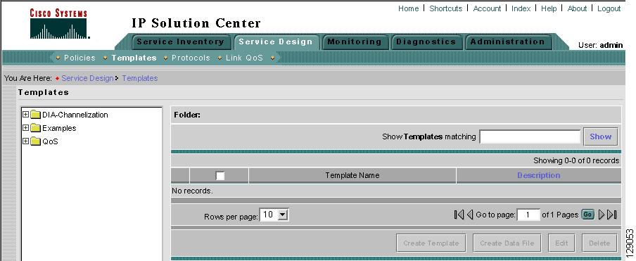
Figure 6-2 Templates
Template examples are shown in the left column. A complete list of template examples is specified in the "Template Examples" section. A complete list of Repository variables is shown in the "Summary of Repository Variables" section.
Step 2
•
•
•
View Templates Tree and Data Pane
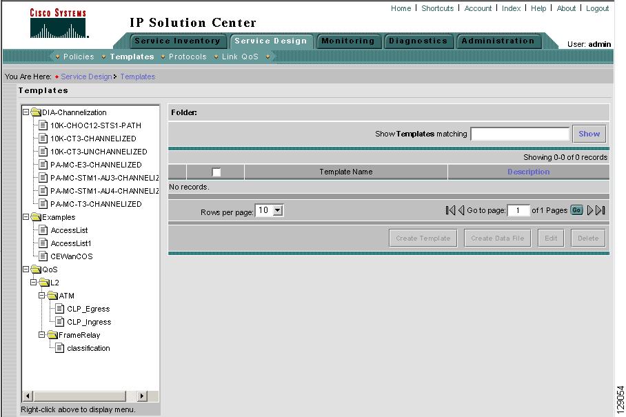
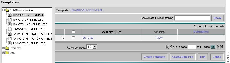
When you navigate to Service Design > Templates, you receive a window as shown in Figure 6-3, "Tree and Data Pane Structure."
The Templates tree is in the left column. You can continue clicking the + sign next to each created folder and subfolder until you get to the last level of information. The last possible level is the template name. Data file information is not kept in the tree.
The right section of the window is the data pane. The name of the folder or template is in the upper-left corner. When you select the check box next to the template or data file information, the Create Template, Create Data File, Edit, or Delete buttons are enabled as described in the following sections.
When there are many templates in a folder or many data files in a template, the Show Template Matching or Show Data File Matching filter in the upper right-hand corner of the data pane can be very useful. For example, you might just want to work with templates or data files that start with abc. In this case, enter abc* in the field and then click the Show button. Only the templates or data files that start with abc appear.
You can also View configurations when the table displays data files.
Figure 6-3 Tree and Data Pane Structure
Create Folders and Subfolders
To create a new folder or subfolder, follow these steps:
Step 1
Step 2
Note
Step 3
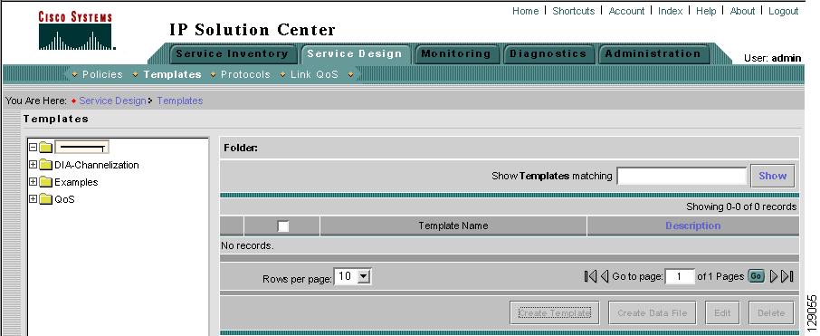
Figure 6-4 Folder Naming
Copying Folders or Subfolders
To copy a folder or subfolder and paste it into another folder or subfolder, follow these steps:
Step 1
Step 2
Step 3
Note
Create Template
You can either create a new template in an existing folder or you can create a new folder first and then create the template. To create a new folder, see the section "Create Folders and Subfolders".
To create a new template, follow these steps:
Step 1
Step 2
Step 3
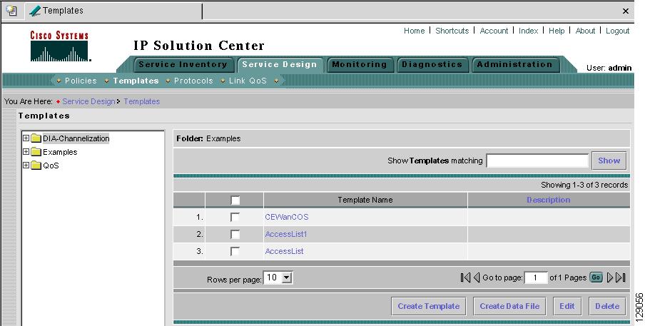
Figure 6-5 Folder with Existing Templates
Step 4
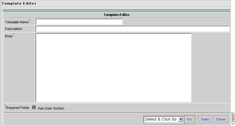
Figure 6-6 Template Editor
Step 5
•
•
•
Note
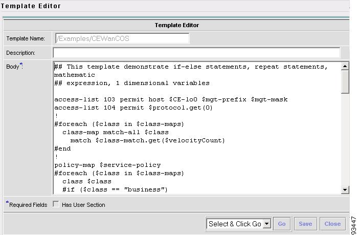
An example template is shown in Figure 6-7, "Example Template."
Figure 6-7 Example Template
ISC has the template system predefined variable $TMSystem that can be used within the template body text to access template system functions. The syntax is as follows, where, $ipAddrMask is a string that contains an IP address and its mask in the format of: 10.33.4.5/30:
$TMSystem.getAddr ($ipAddrMask) returns: 10.33.4.5
$TMSystem.getMask ($ipAddrMask) returns: 255.255.255.252
$TMSystem.getReverseMask ($ipAddrMask) returns: 0.0.0.3
$TMSystem.getNetworkAddr ($ipAddrMask) returns: 10.33.4.4
$TMSystem.getClassfulNetworkAddr ($ipAddrMask) returns: 10.0.0.0
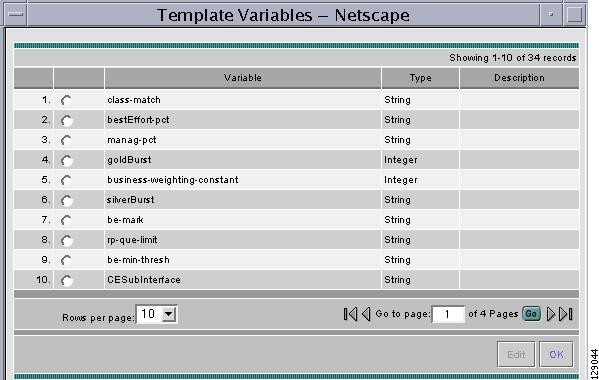
Step 6
Figure 6-8 Template Variables
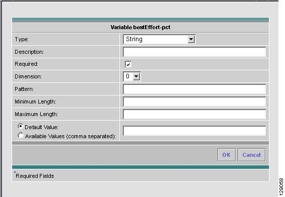
Step 7
Figure 6-9 Variable Definition—Type String
Step 8
•
•
•
•
•
•
•
Step 9
•
•
•
•
•
•
•
•
After you enter all the data, click OK to accept this information for the specified variable; continue editing all variables you want to change in this same way, then click OK in a window such as Figure 6-8, which now includes these updated variables; click Save and then Close or click Close and when asked, agree to Save for a window such as Figure 6-6. Create a Data File is shown in the "Create Data File" section, Edit is shown in the "Edit" section, and Delete is shown in the "Delete" section.
Step 10
•
•
•
•
•
•
•
After you enter all the data, click OK to accept this information for the specified variable; continue editing all variables you want to change in this same way, then click OK in a window such as Figure 6-8, which now includes these updated variables; click Save and then Close or click Close and when asked, agree to Save for a window such as Figure 6-6. Create a Data File is shown in the "Create Data File" section, Edit is shown in the "Edit" section, and Delete is shown in the "Delete" section.
Figure 6-10 Variable Definition—Type Integer
Step 11
•
•
•
•
•
•
•
After you enter all the data, click OK to accept this information for the specified variable; continue editing all variables you want to change in this same way, then click OK in a window such as Figure 6-8, which now includes these updated variables; click Save and then Close or click Close and when asked, agree to Save for a window such as Figure 6-6. Create a Data File is shown in the "Create Data File" section, Edit is shown in the "Edit" section, and Delete is shown in the "Delete" section.
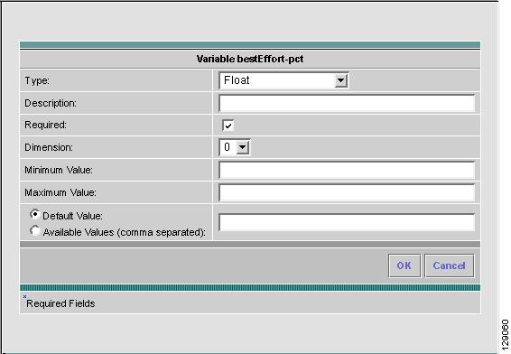
Figure 6-11 Variable Definition—Type Float
Step 12
•
•
•
•
•
•
•
After you enter all the data, click OK to accept this information for the specified variable; continue editing all variables you want to change in this same way, then click OK in a window such as Figure 6-8, which now includes these updated variables; click Save and then Close or click Close and when asked, agree to Save for a window such as Figure 6-6. Create a Data File is shown in the "Create Data File" section, Edit is shown in the "Edit" section, and Delete is shown in the "Delete" section.
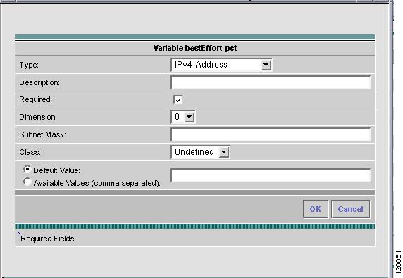
Figure 6-12 Variable Definition—Type IPv4
Step 13
•
•
•
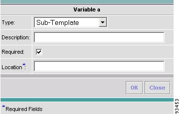
The variable varName is defined as the subtemplate type (by selecting Variables and clicking Go). The Sub-Template defined earlier is called and you must provide the subtemplate path. The syntax is as follows:
$<varName>.callWithDatafile (<DatafileName>)
After you enter all the data, click OK to accept this information for the specified variable; continue editing all variables you want to change in this same way, then click OK in a window such as Figure 6-8, which now includes these updated variables; click Save and then Close or click Close and when asked, agree to Save for a window such as Figure 6-6. Create a Data File is shown in the "Create Data File" section, Edit is shown in the "Edit" section, and Delete is shown in the "Delete" section.
Figure 6-13 Variable Definition—Type Sub-Template
Step 14
•
•
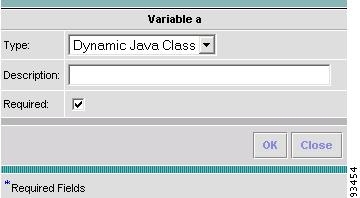
The variable varName is defined as the Dynamic Java Class type (by selecting Variables and clicking Go). The syntax is as follows:
$<varName>.<method_name_in_Java_class> ([<parameters>])
After you enter all the data, click OK to accept this information for the specified variable; continue editing all variables you want to change in this same way, then click OK in a window such as Figure 6-8, which now includes these updated variables; click Save and then Close or click Close and when asked, agree to Save for a window such as Figure 6-6. Create a Data File is shown in the "Create Data File" section, Edit is shown in the "Edit" section, and Delete is shown in the "Delete" section.
Figure 6-14 Variable Definition—Type Dynamic Java Class
Step 15
•
•
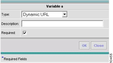
The variable varName is defined as the Dynamic URL type (by selecting Variables and clicking Go). The syntax is as follows:
$<varName>.callURL (<url-address>)
After you enter all the data, click OK to accept this information for the specified variable; continue editing all variables you want to change in this same way, then click OK in a window such as Figure 6-8, which now includes these updated variables; click Save and then Close or click Close and when asked, agree to Save for a window such as Figure 6-6. Create a Data File is shown in the "Create Data File" section, Edit is shown in the "Edit" section, and Delete is shown in the "Delete" section.
Figure 6-15 Variable Definition—Type Dynamic URL
Copying Templates
To copy a template and paste it into another folder, follow these steps:
Step 1
Step 2
Step 3
Note
Create Data File
You can create a new data file from an existing template. If the template you want is not available, go to the "Create Template" section.
To create a data file, follow these steps:
Step 1
Step 2
1.
2.
Step 3
Figure 6-16 Choose Existing Template > Create Data File
Select the check box for the template for which you want to create a data file and click Create Data File. Then proceed to Step 5.
Otherwise, proceed to Step 4.
Step 4
Figure 6-17 Choose Existing Template > Create Data File
Click Create Data File and proceed to Step 5.
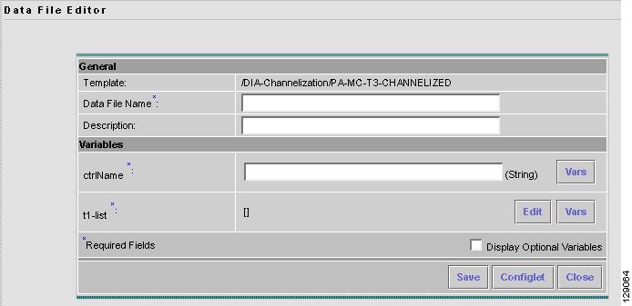
Step 5
Figure 6-18 Template Data File Editor
Step 6
•
•
Step 7
If t1-list is a Dynamic Java Class variable, you must enter the entire Java Class package name. For example: com.cisco.isc.class_name.
Step 8
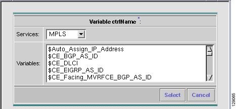
Figure 6-19 Template Data File Editor
Click the Services drop-down list to have access to variables for:
•
•
•
•
Then click the entry in Variables that you want to use and click Select.
If you have a 0 dimensional entry (set as Dimension 0 when creating a template), you can only enter variables in the provided field.
Step 9
Proceed to Step 10 for information about a 1 dimensional array.
Proceed to Step 13 for information about a 2 dimensional array.
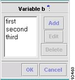
Step 10
Figure 6-20 Editing a One-Dimensional Array
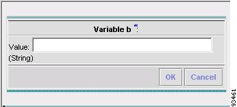
Step 11
Figure 6-21 Adding a Variable
Step 12
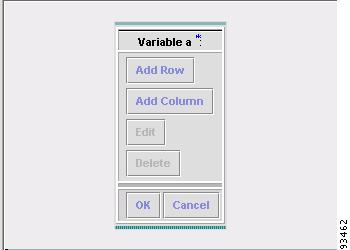
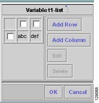
Step 13
Figure 6-22 Editing a Two-Dimensional Array
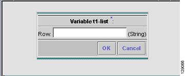
Step 14
Figure 6-23 Enter Row Information
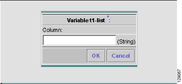
Step 15
Figure 6-24 Enter Column Information
Step 16
Figure 6-25 Two-Dimensional Array Results
Step 17
Step 18
Step 19
Step 20
Edit
To edit a Template or Data File, follow these steps:
Step 1
Step 2
Step 3
Figure 6-26 Choose Existing Template > Edit
Figure 6-27 Choose Existing Data File > Edit
Step 4
Note
Step 5
Step 6
Delete
To delete a Template or Data File, follow these steps:
Step 1
Step 2
Step 3
Figure 6-28 Choose Existing Template > Delete
Figure 6-29 Choose Existing Data File > Delete
Step 4
Note
Step 5
Step 6
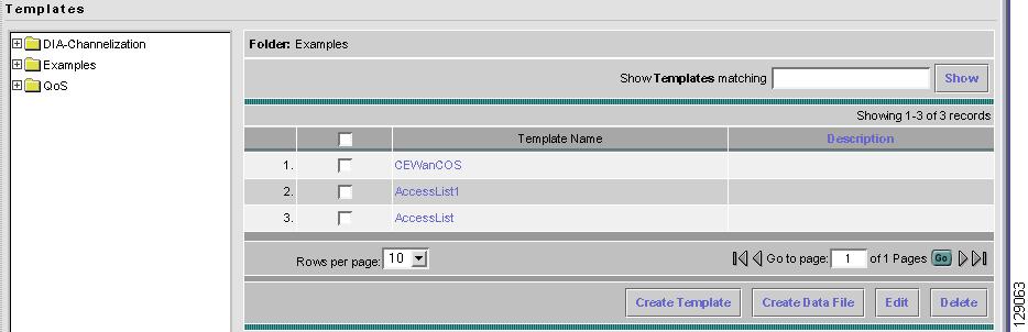
Template Examples
In the left column, the hierarchy pane, of Service Design > Templates, as shown in Figure 6-2, "Templates," template examples appear. See Table 6-1, "Template Examples and Their Descriptions."
Summary of Repository Variables
This section contains the following tables:
•
•
•
•
Table 6-2 provides a summary of the L2VPN Repository variables available from ISC Templates.
Table 6-3 provides a summary of the MPLS Repository variables available from ISC Templates.
Table 6-4 provides a summary of the QoS Repository variables available from ISC Templates.
Table 6-5 provides a summary of the VPLS Repository variables available from ISC Templates.
Link QoS
The Link QoS feature provides separate settings for IP QoS and Ethernet QoS.
IP QoS deals with link-level QoS settings that depend on Layer2 encapsulation and link bandwidth, such as Aggregate Shapers (FRTS; ATM Shapers, parent-level cb-shaper), Link Efficiency Mechanisms (FRF.12, LFIoMLPPP, and cRTP), and Interface-based Aggregated Rate Limiter.
Ethernet QoS allows you to configure Shape, Bandwidth, and Trust (CoS or DSCP) settings.
You can create a link QoS setting for a network independent of a VPN service. To manage IP Link QoS Settings for an MPLS service or Ethernet Link QoS Settings for an L2VPN service, see Cisco IP Solution Center Quality of Service User Guide, 4.1.