Table Of Contents
Creating and Manipulating Cisco ANA Business Configuration
Creating a VPN
Moving a Virtual Router
Adding a Tunnel
Creating an LCA
Deleting an LCA
Moving an LCP
Moving an LCA
Jumping to the Adjacent LCP
Renaming a Business Element
Deleting a Business Element
Creating and Manipulating Cisco ANA Business Configuration
This chapter describes how to change the business element configuration using the functionality provided in the Service View map. For more information about the business configuration, see Introducing the Cisco ANA Business Configuration.
Note
All the operations described in this chapter have the affect of rearranging the map and do not affect other maps.
•
Creating a VPN—Describes how to manually create VPNs.
•
Moving a Virtual Router—Describes how to move a Virtual Router (including its Sites) from one VPN to another.
•
Adding a Tunnel—Describes how to add tunnels to a VPN.
•
Creating an LCA—Describes how manually create an LCA.
•
Deleting an LCA—Describes how to delete an LCA.
•
Moving an LCP—Describes how to move an LCP to another VPN or LCA.
•
Moving an LCA—Describes how to move the LCA to another VPN.
•
Jumping to the Adjacent LCP—Describes how to jump from one peer to the adjacent peer.
•
Renaming a Business Element—Describes how to rename business elements from the business model.
•
Deleting a Business Element—Describes how to delete business elements from the business model.
Note
The LCA/LCP operations, like moving is an operation that logically moves the business element from one VPN to another (so all maps that contain the same VPN are automatically affected). A move operation that is performed inside the same VPN has the affect of rearranging the map and does not affect other maps. This also applies to the LCA/LCP operations adding and deleting.
Creating a VPN
The user can change the business configuration by manually creating VPNs. The VPNs that are manually created do not contain Virtual Routers and Sites.
To create a VPN
Step 1
Select the root of the map in the Cisco ANA NetworkVision window's tree pane.
Step 2
On the toolbar, click Add VPN.
or
Select Add VPN from the File menu. The Add Business Element to <Root> dialog box is displayed.
Step 3
Click New. The Create Business Element dialog box is displayed.
The following fields are displayed in the Create Business Element dialog box:
•
Name: The unique name of the new VPN business element.
•
Icon: The path to the icon on the Server.
•
Description: An additional description of the VPN business element (optional).
Step 4
Type a unique name for the new VPN business element in the Name field.
Note
VPN business element names are case sensitive.
Note
For information about renaming a VPN, see the Cisco Active Network Abstraction NetworkVision User Guide.
Step 5
Specify the path to the required icon (optional).
Note
If a path is not specified to an icon the default VPN business element icon is used (for more information about icons see 1-7).
Step 6
Type a description for the new VPN business element (optional).
Step 7
Click OK. The new VPN business element is added to the list in the Add Business Element to <Root> dialog box.
For more information about loading the newly created VPN business element in the Service View map, see Adding a VPN.
Moving a Virtual Router
The user can move a Virtual Router (including its Sites) from one VPN to another after a VPN has been created and added to the Service View map.
Note
Moving a Virtual Router moves all the Virtual Router's Sites as well.
To move a Virtual Router
Step 1
Select the required Virtual Router that you want to move in the Cisco ANA NetworkVision window's tree pane or the map pane.
Step 2
Right-click to display the shortcut menu and select Edit | Move selected.
Step 3
Select the required VPN in the tree pane or the map pane to where you want to move the Virtual Router.
Warning 
When a Virtual Router is moved from one VPN to another it affects all users that have the Virtual Router loaded in their Service View map.
Step 4
Right-click to display the shortcut menu and select Edit | Move here. The Virtual Router (including its Sites) is now displayed under the selected VPN in the tree pane and in the map pane.
Adding a Tunnel
The user can add tunnels and/or partially configured tunnels to a VPN. LCPs with a missing peer are marked with the stranded icon (for more information about icons see 1-7). Each tunnel can only be associated with one VPN.
Note
The state of the topology between LCPs does not reflect the actual state of the network; it is only an Logical link.
The user can either:
•
Add a tunnel (LCP) to an LCA that has been manually created (for more information about manually creating an LCA, see Creating an LCA),
or
•
Add a tunnel (LCP) directly to a VPN in which case the LCA is automatically created beneath the VPN.
To add a tunnel
Step 1
Right-click on the required LCA or VPN in then Cisco ANA NetworkVision window's tree pane or map pane to display the shortcut menu.
Step 2
Select Topology | Add Tunnel. The Add Tunnels dialog box is displayed.
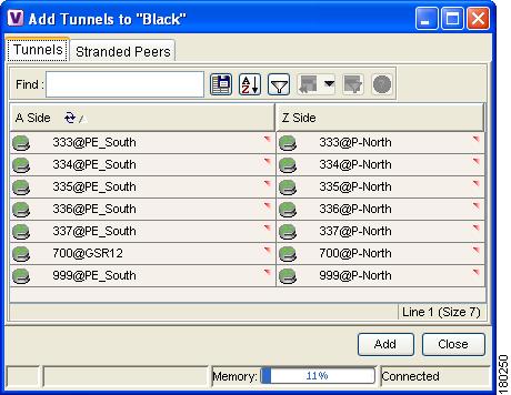
Figure 3-1 Add Tunnels dialog box
The Add Tunnels dialog box displays only those tunnels that are not currently attached to a VPN. It is divided into the Tunnels and Stranded Peers tabs. The Tunnels tab displays the list of PWE3 tunnels (including both tunnel edges).
The Stranded Peers tab displays the list of partially configured tunnel edges. The Add Tunnels dialog box enables the user to add an LCP without its peer, for example, when there is a half-managed tunnel or an Agent that fails to load or a device that has been incorrectly configured.
Step 3
Select the required tunnel or stranded peer and click Add.
•
If the tunnel or stranded peer is added beneath an LCA, the link between the peers is displayed in the map pane.
•
If the tunnel or stranded peer is added beneath a VPN, Cisco ANA detects the starting point of the PWE3 tunnel edges and groups all the LCPs that start at the same device automatically together into an LCA (aggregation) beneath the VPN.
Note
If a tunnel exists between VPNs (namely, an extranet tunnel) add a tunnel to one VPN and then move one LCP (peer) to the VPN with which you want to create the extranet tunnel.
The user can remove a tunnel that was added to an LCA or VPN.
To remove a tunnel
Step 1
Right-click on the required LCP in the in the Cisco ANA NetworkVision window's tree pane or map pane to display the shortcut menu.
Step 2
Select Topology | Remove Tunnel. Both sides of the tunnel are removed from the Service View map and are displayed in the Add Tunnels dialog box again.
If the deleted tunnel formed part of an LCA that was created manually, the LCA is still displayed in the tree pane or map pane.
If the deleted tunnel formed part of an LCA that was created automatically the LCA is removed from the tree pane or map pane, provided that there are no other LCPs in the LCA.
Note
MPLS TE Tunnels cannot be viewed in VPN Service View maps however; you can view device and topology information. For more information, page 5-13.
Creating an LCA
The user can manually create an LCA and populate it by:
•
Moving selected LCPs to the LCA. For more information, see Moving an LCP.
•
Adding tunnels (LCPs) to the LCA. For more information, see Adding a Tunnel.
For more information about LCAs that are created automatically, see Adding a Tunnel.
To create an LCA
Step 1
Select the required VPN in the Cisco ANA NetworkVision window's tree pane or map pane.
Step 2
Right-click to display the shortcut menu and select Create LCA. The Create LCA dialog box is displayed.
Step 3
Type a unique name for the new LCA.
Step 4
Click OK. The new LCA is created and displayed in the tree pane the Cisco ANA NetworkVision window beneath the selected VPN, and in the map pane.
Deleting an LCA
Cisco ANA enables the user to delete an LCA that was manually created if it has no LCPs or if all the LCPs have the reconciliation icon.
Note
The user also has the option to move the LCA to another VPN. For more information, see Moving an LCA.
To delete the LCA
Step 1
Select the required LCA in the Cisco ANA NetworkVision window's tree pane or map pane.
Step 2
Right-click to display the shortcut menu and select Delete. A confirmation message is displayed.
Step 3
Click Yes to delete the LCA. The selected LCA is deleted from the database and Service View maps of all users.
Note
When the user deletes an LCA, the LCA information is deleted from the database.
Moving an LCP
The user can move an LCP to another VPN or LCA in the Service View map.
To move an LCP:
Step 1
Right-click on the required LCP in the Cisco ANA NetworkVision window's tree pane or map pane to display the shortcut menu.
Step 2
Select Edit | Move selected.
Step 3
Right-click on the required VPN or LCA in the tree pane or map pane to where you want to move the LCP to display the shortcut menu.
Step 4
Select Edit | Move here. The single selected LCP moves to the required VPN or LCA, and is displayed in the tree pane and map pane of the selected VPN or LCA.
Note
If an LCP is moved to a VPN then an LCA is automatically created for it.
Moving an LCA
The user can move the LCA to another VPN in the Service View map. When the LCA is moved all the LCPs beneath the LCA also move.
To move an LCA:
Step 1
Right-click on the required LCA in the Cisco ANA NetworkVision window's tree pane or map pane to display the shortcut menu.
Step 2
Select Edit | Move selected.
Step 3
Right-click on the required VPN in the tree pane or map pane where you want to move the LCA to display the shortcut menu.
Step 4
Select Edit | Move here. The LCA moves to the selected VPN and is displayed in the tree pane and map pane for the selected VPN.
Note
All the LCPs move along with the LCA.
Jumping to the Adjacent LCP
The Service View map displays multiple tunnels. The user can quickly and easily access the selected LCP's peer appearing in the same map.
Note
You can only jump from one LCP to a peer LCP, provided the other peer is displayed in the same map.
To jump to the adjacent LCP:
Step 1
Select the required LCP in the Cisco ANA NetworkVision window's tree pane or map pane.
Step 2
Right-click on the LCP to display the shortcut menu, and select Jump to Adjacent. The adjacent LCP is highlighted in the tree pane and map pane.
Renaming a Business Element
You can rename a business element in Service View maps using the shortcut menu.
To rename a business element:
Step 1
Right-click on the required business element in the Cisco ANA NetworkVision window's tree pane or map pane to display the shortcut menu.
Step 2
Select Rename. The Rename Node dialog box is displayed.
Step 3
Type a new name and click OK. The changed business element name appears in the Cisco ANA NetworkVision window's tree pane and map pane.
Note
When a business element is renamed it affects all users that have the business element loaded in their Service View map.
Deleting a Business Element
The user can delete business elements from the business model (database). When a business element is deleted it is deleted from the database (irreversible) and is no longer displayed in the Add Business Element to <Root> dialog box. A business element is generally deleted when the physical element no longer exists.
Caution 
When a business element is deleted it affects all users that have the business element loaded in their Service View map.
The table below describes the checks performed by Cisco ANA before the user can delete the required business element.
Business Element
|
Requirements
|
Layer 3 VPN
|
• There are no Virtual Routers.
• The Virtual Routers, and Sites display the reconciliation icon.
|
Virtual Router
|
• There are no network elements (VRFs and interfaces) contained in the Virtual Router.
• The Virtual Routers, VRFs, Sites and interfaces display the reconciliation icon.
|
Site
|
• There are no interfaces connected/bound to the VRF.
• The Sites and interfaces display the reconciliation icon.
|
Layer 2 VPN
|
• There are no LCPs beneath the LCA.
• The LCPs display the reconciliation icon.
|
LCA
|
• There are no LCPs.
• All the nested LCPs display the reconciliation icon.
|
To delete a business element:
Step 1
Right-click on the required business element in the Cisco ANA NetworkVision window's tree pane or map pane to display the shortcut menu.
Note
Make sure that the VPN business element meets the requirements set out in the table. If the requirements are not met, you will be unable to delete the business element.
Step 2
Select Delete. A confirmation message is displayed.
Step 3
Click Yes to delete the currently selected element or click Yes to All to delete multiple selected elements. The selected business element is deleted from the business configuration of all users.