Feedback
Table Of Contents
Configuring the Access VPN to Work with Remote AAA
Step 2—Configuring the Home Gateway
Step 3—Configuring the CiscoSecure ACS UNIX Server
Step 4—Configuring the CiscoSecure ACS NT Server
Step 1—Checking the NAS Final Running Configuration
Step 2—Checking the Home Gateway Final Running Configuration
Step 4—Pinging the Home Gateway
Step 5—Displaying Active Call Statistics on the Home Gateway
Step 7—Verifying That the Virtual-Access Interface Is Up and That LCP Is Open
Step 8—Viewing Active L2F Tunnel Statistics
Troubleshooting the Access VPN
Step 1—Comparing Your Debug Output to the Successful Debug Output
Step 2—Troubleshooting L2F Negotiation
Misconfigured NAS Tunnel Secret
Misconfigured Home Gateway Tunnel Secret
Step 3—Troubleshooting PPP Negotiation
Step 4—Troubleshooting AAA Negotiation
Error Contacting RADIUS Server
Misconfigured AAA Authentication
Configuring the Access VPN to Work with Remote AAA
Introduction
In this third task, the ISP and the enterprise customer:
•
Reconfigure the NAS and home gateway to work as an access VPN using remote AAA. To ensure that the access VPN is using remote AAA, the ISP and enterprise customer modify the AAA and VPN configurations on the NAS and home gateway.
•
•
•
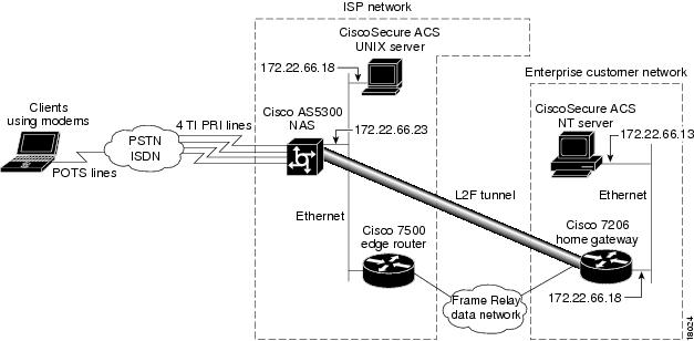
The ISP configures the NAS and CiscoSecure UNIX. The enterprise customer configures the home gateway and CiscoSecure NT. shows the access VPN network topology.
Figure 17 Access VPN Topology Using Remote AAA
Once the ISP and enterprise customer have completed this task, the network will function as follows:
•
•
•
•
•
•
Configuring the Access VPN
To configure the access VPN solution to work with remote AAA, follow these steps:
•
•
•
Step 1—Configuring the NAS
In this step, the ISP:
•
•
•
Instruct AAA to first use the local database and then use the RADIUS server (CiscoSecure NT) for PPP and VPN authentication.
The order of authentication methods is local first and RADIUS second because the tunnel is authenticated locally and the user's domain name is authenticated by the CiscoSecure UNIX server.
Instruct AAA to use the CiscoSecure UNIX server to authorize network-related service requests.
ISP_NAS(config)# radius-server host 172.22.66.18Enter the CiscoSecure UNIX server's IP address.
ISP_NAS(config)# radius-server key ciscoDefine a key to decrypt the data that runs between the NAS and the CiscoSecure UNIX server.
Note
Cisco's RADIUS has a hard-coded password of "cisco"; this is separate from the NAS and home gateway passwords used to authenticate each other.
ISP_NAS(config)# no vpdn-group 1Remove the VPN1 group. All of the tunneling information will now be retrieved using RADIUS at the CiscoSecure UNIX server.
1 The Cisco IOS command syntax uses the more specific term virtual private dialup network (VPDN) instead of VPN.
Step 2—Configuring the Home Gateway
In this step, the enterprise customer:
•
•
•
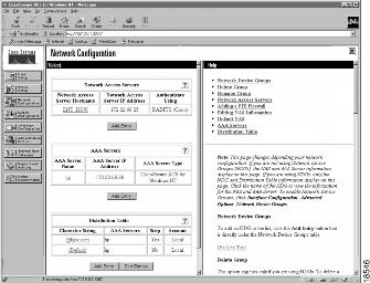
Step 3—Configuring the CiscoSecure ACS UNIX Server
In this step, the ISP configures CiscoSecure ACS UNIX to:
•
•
•
The following procedure shows how to configure CiscoSecure UNIX by using RADIUS as the security protocol.
The ISP can configure CiscoSecure UNIX by:
•
•
The following procedure shows the CLI method of configuring CiscoSecure UNIX.
Note
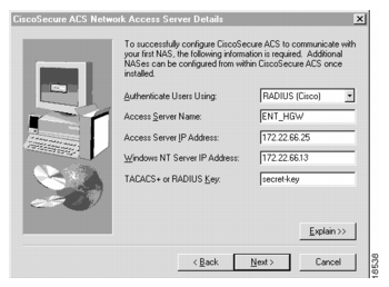
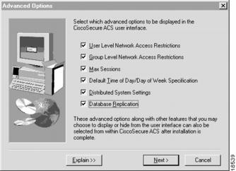
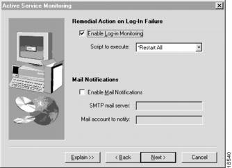
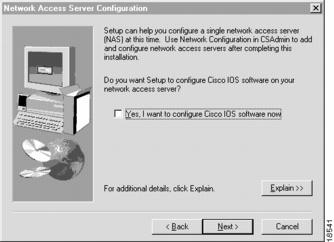
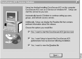
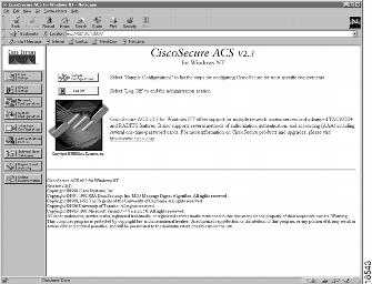
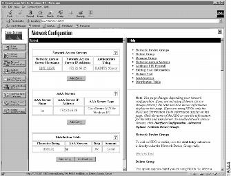
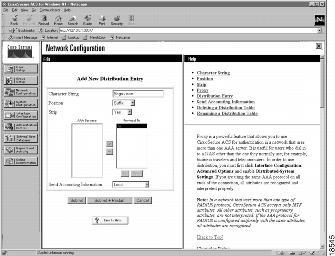
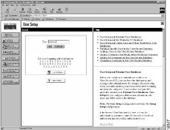
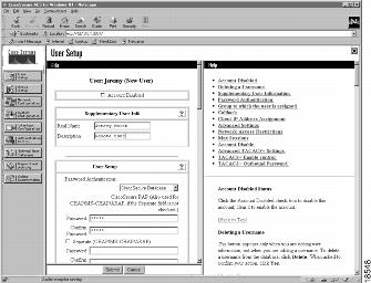
Step 4—Configuring the CiscoSecure ACS NT Server
In this step, the enterprise customer:
•
•
•
In CiscoSecure NT, basic accounting services are configured by default.
Note
Verifying the Access VPN
This section describes how to verify that the end-to-end connections function as shown in :
•
•
•
•
•
•
Figure 18 Access VPN Topology Using Remote AAA
After you successfully test these connections, the final end-to-end solution is built. If you experience problems, see "Troubleshooting the Access VPN."
Step 1—Checking the NAS Final Running Configuration
Enter the show running-config command in privileged EXEC mode to make sure the NAS accepted the commands you entered:
ISP_NAS# show running-configBuilding configuration...Current configuration:!version 11.3service timestamps debug datetime msecservice timestamps log datetime msecservice password-encryption!hostname ISP_NAS!aaa new-modelaaa authentication ppp default radiusaaa authorization network default radiusenable secret 5 $1$AXl/$27hOM6j51a5P76Enq.LCf0!username jane-admin password 7 0501090A6C5C4F1A0A1218000Fusername ENT_HGW password 7 104D000A0618username ISP_NAS password 7 13061E010803vpdn enable!vpdn search-order domain dnisasync-bootp dns-server 171.68.10.70 171.68.10.140isdn switch-type primary-5ess!controller T1 0framing esfclock source line primarylinecode b8zspri-group timeslots 1-24!controller T1 1framing esfclock source line secondarylinecode b8zspri-group timeslots 1-24!controller T1 2framing esfclock source internallinecode b8zspri-group timeslots 1-24!controller T1 3framing esfclock source internallinecode b8zspri-group timeslots 1-24!!interface Ethernet0ip address 172.22.66.23 255.255.255.192!interface Serial0:23no ip addressisdn switch-type primary-5essisdn incoming-voice modemno cdp enable!interface Serial1:23no ip addressisdn switch-type primary-5essisdn incoming-voice modemno cdp enable!interface Serial2:23no ip addressisdn switch-type primary-5essisdn incoming-voice modemno cdp enable!interface Serial3:23no ip addressisdn switch-type primary-5essisdn incoming-voice modemno cdp enable!interface FastEthernet0no ip addressshutdown!interface Group-Async1ip unnumbered Ethernet0encapsulation pppasync mode interactiveno peer default ip addressppp authentication chap papgroup-range 1 96!ip classlessip route 0.0.0.0 0.0.0.0 172.22.66.1!radius-server host 172.22.66.16 auth-port 1645 acct-port 1646radius-server key cisco!line con 0transport input noneline 1 96autoselect during-loginautoselect pppmodem InOutline aux 0line vty 0 4!endStep 2—Checking the Home Gateway Final Running Configuration
Enter the more system:running-config command in privileged EXEC mode to make sure the home gateway accepted the commands you entered:
ENT_HGW# more system:running-configBuilding configuration...Current configuration:!version 12.0service timestamps debug datetime msecservice timestamps log uptimeservice password-encryption!hostname ENT_HGW!aaa new-modelaaa authentication login default localaaa authentication ppp default local radiusaaa authorization network default radiusaaa accounting network default start-stop radiusenable secret 5 $1$44oH$gZlAZLwylZJSNKGDk.BKb0!username jane-admin password 7 00001C05username ISP_NAS password 7 070C285F4D06username ENT_HGW password 7 104D000A0618ip subnet-zeroip domain-name cisco.comip name-server 171.68.10.70!vpdn enable!vpdn-group 1accept dialin l2f virtual-template 1 remote ISP_NASlocal name ENT_HGW!async-bootp dns-server 172.23.1.10 172.23.2.10async-bootp nbns-server 172.23.1.11 172.23.2.11!!!interface FastEthernet0/0ip address 172.22.66.25 255.255.255.192no ip directed-broadcast!...interface Virtual-Template1ip unnumbered FastEthernet0/0peer default ip address pool defaultppp authentication chap!ip local pool default 172.30.2.1 172.30.2.96ip classlessip route 0.0.0.0 0.0.0.0 172.22.66.1!radius-server host 172.22.66.13 auth-port 1645 acct-port 1646radius-server key cisco!line con 0transport input noneline aux 0line vty 0 4password 7 045F0405!endStep 3—Dialing in to the NAS
From the client, dial in to the NAS by using the PRI telephone number assigned to the NAS' T1 trunks. Sometimes this telephone number is called the hunt group number.
As the call comes into the NAS, a LINK-3-UPDOWN message automatically appears on the NAS' terminal screen. In this example, the call comes in to the NAS on asynchronous interface 14. The asynchronous interface is up.
*Jan 1 21:22:18.410: %LINK-3-UPDOWN: Interface Async14, changed state to up
Note
Step 4—Pinging the Home Gateway
From the client, ping the home gateway. From the client's Windows 95 desktop:
(a)
(b)
(c)
(d)
(e)
Step 5—Displaying Active Call Statistics on the Home Gateway
From the home gateway, enter the show caller command and show caller user name command to verify that the client received an IP address. This example shows that Jeremy is using interface virtual-access 1 and IP address 172.30.2.1. The network administrator jane-admin is using console 0.
ENT_HGW# show callerLine User Service Activecon 0 jane-admin TTY 00:00:25Vi1 jeremy@hgw.com PPP L2F 00:01:28ENT_HGW# show caller user jeremy@hgw.comUser: jeremy@hgw.com, line Vi1, service PPP L2F, active 00:01:35PPP: LCP Open, CHAP (<- AAA), IPCPIP: Local 172.22.66.25, remote 172.30.2.1VPDN: NAS ISP_NAS, MID 1, MID openHGW ENT_HGW, NAS CLID 36, HGW CLID 1, tunnel openCounts: 105 packets input, 8979 bytes, 0 no buffer0 input errors, 0 CRC, 0 frame, 0 overrun18 packets output, 295 bytes, 0 underruns0 output errors, 0 collisions, 0 interface resetsStep 6—Pinging the Client
From the home gateway, ping Jeremy's PC at IP address 172.30.2.1:
ENT_HGW# ping 172.30.2.1Type escape sequence to abort.Sending 5, 100-byte ICMP Echos to 172.30.2.1, timeout is 2 seconds:!!!!!Success rate is 100 percent (5/5), round-trip min/avg/max = 128/132/152 msStep 7—Verifying That the Virtual-Access Interface Is Up and That LCP Is Open
From the home gateway, enter the show interface virtual-access 1 command to verify that the interface is up, LCP is open, and no errors are reported:
ENT_HGW# show interface virtual-access 1Virtual-Access1 is up, line protocol is upHardware is Virtual Access interfaceInterface is unnumbered. Using address of FastEthernet0/0 (172.22.66.25)MTU 1500 bytes, BW 115 Kbit, DLY 100000 usec,reliablility 255/255, txload 1/255, rxload 1/255Encapsulation PPP, loopback not set, keepalive set (10 sec)DTR is pulsed for 5 seconds on resetLCP OpenOpen: IPCPLast input 00:00:02, output never, output hang neverLast clearing of "show interface" counters 3d00hQueueing strategy: fifoOutput queue 1/40, 0 drops; input queue 0/75, 0 drops5 minute input rate 0 bits/sec, 0 packets/sec5 minute output rate 0 bits/sec, 0 packets/sec114 packets input, 9563 bytes, 0 no bufferReceived 0 broadcasts, 0 runts, 0 giants, 0 throttles0 input errors, 0 CRC, 0 frame, 0 overrun, 0 ignored, 0 abort27 packets output, 864 bytes, 0 underruns0 output errors, 0 collisions, 0 interface resets0 output buffer failures, 0 output buffers swapped out0 carrier transitionsStep 8—Viewing Active L2F Tunnel Statistics
From the home gateway, display active tunnel statistics by entering the show vpdn command and show vpdn tunnel all command:
ENT_HGW# show vpdn% No active L2TP tunnelsL2F Tunnel and SessionNAS CLID HGW CLID NAS Name HGW Name State36 1 ISP_NAS ENT_HGW open172.22.66.23 172.22.66.25CLID MID Username Intf State36 1 jeremy@hgw.com Vi1 openENT_HGW# show vpdn tunnel all% No active L2TP tunnelsL2F TunnelNAS name: ISP_NASNAS CLID: 36NAS IP address 172.22.66.23Gateway name: ENT_HGWGateway CLID: 1Gateway IP address 172.22.66.25State: openPackets out: 52Bytes out: 1799Packets in: 100Bytes in: 7143Troubleshooting the Access VPN
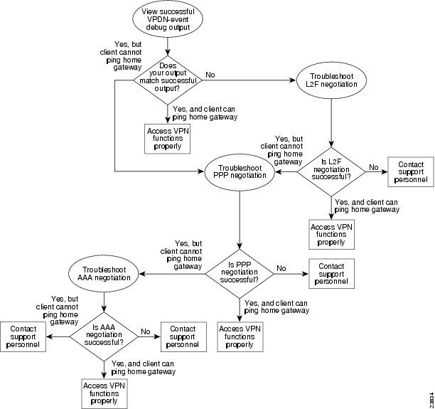
This section provides the ISP and enterprise customer with a methodology for troubleshooting the access VPN as described in . Step 1 shows debug output from a successful call. If your debug output does not match the successful output, follow the remaining steps to begin troubleshooting the network. The bolded lines of debug output indicate important information.
•
•
•
•
Figure 19 Troubleshooting Flow Diagram for Access VPN with Remote AAA
If you are accessing the NAS and home gateway through a Telnet connection, you need to enable the terminal monitor command. This command ensures that your EXEC session is receiving the logging and debug output from the devices.
When you finish troubleshooting, use the undebug all command to turn off all debug commands. Isolating debug output helps you efficiently build a network.
Step 1—Comparing Your Debug Output to the Successful Debug Output
Enable the debug vpdn-event command on both the NAS and the home gateway and dial in to the NAS. The following debug output shows successful VPN negotiation on the NAS and home gateway:
ISP_NAS#Jan 7 00:19:35.900: %LINK-3-UPDOWN: Interface Async9, changed state to upJan 7 00:19:39.532: sVPDN: Got DNIS string As9Jan 7 00:19:39.532: As9 VPDN: Looking for tunnel -- hgw.com --Jan 7 00:19:39.540: As9 VPDN: Get tunnel info for hgw.com with NAS ISP_NAS, IP172.22.66.25Jan 7 00:19:39.540: As9 VPDN: Forward to address 172.22.66.25Jan 7 00:19:39.540: As9 VPDN: Forwarding...Jan 7 00:19:39.540: As9 VPDN: Bind interface direction=1Jan 7 00:19:39.540: As9 VPDN: jeremy@hgw.com is forwardedJan 7 00:19:40.540: %LINEPROTO-5-UPDOWN: Line protocol on Interface Async9, changed state to upENT_HGW#Jan 7 00:19:39.967: VPDN: Chap authentication succeeded for ISP_NASJan 7 00:19:39.967: Vi1 VPDN: Virtual interface created for jeremy@hgw.comJan 7 00:19:39.967: Vi1 VPDN: Set to Async interfaceJan 7 00:19:39.971: Vi1 VPDN: Clone from Vtemplate 1 filterPPP=0 blocking6w5d: %LINK-3-UPDOWN: Interface Virtual-Access1, changed state to upJan 7 00:19:40.051: Vi1 VPDN: Bind interface direction=2Jan 7 00:19:40.051: Vi1 VPDN: PPP LCP accepted rcv CONFACKJan 7 00:19:40.051: Vi1 VPDN: PPP LCP accepted sent CONFACK6w5d: %LINEPROTO-5-UPDOWN: Line protocol on Interface Virtual-Access1, changed state to upIf you see the above debug output but cannot ping the home gateway, go on to "Step 3—Troubleshooting PPP Negotiation."
If you do not see the above debug output, go on to "Step 2—Troubleshooting L2F Negotiation."
Step 2—Troubleshooting L2F Negotiation
This step describes several common misconfigurations that prevent successful L2F negotiation.
•
•
Misconfigured NAS Tunnel Secret
The NAS and the home gateway must both have the same usernames with the same password to authenticate the L2F tunnel. These usernames are called the tunnel secret. In this case study, these usernames are ISP_NAS and ENT_HGW. The password is cisco for both usernames on both systems.
If one of the tunnel secrets on the NAS is incorrect, you will see the following debug output when you dial in to the NAS and the debug vpdn l2x-errors command is enabled on the NAS and home gateway:
ISP_NAS#Jan 1 00:26:49.899: %LINK-3-UPDOWN: Interface Async3, changed state to upJan 1 00:26:54.643: %LINEPROTO-5-UPDOWN: Line protocol on Interface Async3, changed state to upJan 1 00:27:00.559: L2F: Resending L2F_OPEN, time #1Jan 1 00:27:05.559: L2F: Resending L2F_ECHO, time #1Jan 1 00:27:05.559: L2F: Resending L2F_OPEN, time #2Jan 1 00:27:10.559: L2F: Resending L2F_ECHO, time #2Jan 1 00:27:10.559: L2F: Resending L2F_OPEN, time #3Jan 1 00:27:15.559: L2F: Resending L2F_ECHO, time #3Jan 1 00:27:15.559: L2F: Resending L2F_OPEN, time #4Jan 1 00:27:20.559: L2F: Resending L2F_ECHO, time #4Jan 1 00:27:20.559: L2F: Resending L2F_OPEN, time #5Jan 1 00:27:25.559: L2F: Resending L2F_ECHO, time #5Jan 1 00:27:25.559: L2F: Resend packet (type 2) around too long, time to kill off the tunnelISP_NAS#ENT_HGW#Jan 1 00:26:53.645: L2F: Packet has bogus2 key C8353FAB B63691215w6d: %VPDN-6-AUTHENFAIL: L2F HGW , authentication failure for tunnel ISP_NAS; Invalid key5w6d: %VPDN-5-UNREACH: L2F NAS 172.22.66.23 is unreachableJan 1 00:27:00.557: L2F: Gateway received tunnel OPEN while in state closedENT_HGW#The phrase "time to kill of the tunnel" in the NAS debug output indicates that the tunnel was not opened. The phrase "Packet has bogus2 key" in the home gateway debug output indicates that the NAS has an incorrect tunnel secret.
To avoid this problem, make sure that you configure both the NAS and home gateway for the same two tunnel secret usernames with the same password.
Misconfigured Home Gateway Tunnel Secret
If one of the tunnel secret usernames on the home gateway is incorrect, the following debug output appears when you dial in to the NAS and the debug vpdn l2x-errors command is enabled on the NAS and home gateway.
ISP_NAS#Jan 1 00:45:27.123: %LINK-3-UPDOWN: Interface Async7, changed state to upJan 1 00:45:30.939: L2F: Packet has bogus1 key B6C656EE 5FAC6B3Jan 1 00:45:30.939: %VPDN-6-AUTHENFAIL: L2F NAS ISP_NAS, authentication failurefor tunnel ENT_HGW; Invalid keyJan 1 00:45:31.935: %LINEPROTO-5-UPDOWN: Line protocol on Interface Async7, changed state to upJan 1 00:45:35.559: L2F: Resending L2F_OPEN, time #1Jan 1 00:45:35.559: L2F: Packet has bogus1 key B6C656EE 5FAC6B3ENT_HGW#Jan 1 00:45:30.939: L2F: Tunnel authentication succeeded for ISP_NASJan 1 00:45:35.559: L2F: Gateway received tunnel OPEN while in state openJan 1 00:45:40.559: L2F: Gateway received tunnel OPEN while in state openJan 1 00:45:45.559: L2F: Gateway received tunnel OPEN while in state openJan 1 00:45:50.559: L2F: Gateway received tunnel OPEN while in state openNotice how this output is similar to the debug output you see when the NAS has a misconfigured tunnel secret username. This time you see the phrase "Packet has bogus1 key" on the NAS instead of the home gateway. This tells you that the home gateway has an incorrect tunnel secret username.
To avoid this problem, make sure that you configure both the NAS and home gateway for the same two tunnel secret usernames with the same password.
Misconfigured Tunnel Name
If the NAS and home gateway do not have matching tunnel names, they cannot establish an L2F tunnel. On the home gateway, these tunnel names are configured under the vpdn-group 1 command by using the local name command. On the NAS, these names are configured on the CiscoSecure UNIX server.
The home gateway must be configured to accept tunnels from the name the NAS sends it. This is done using the accept dialin l2f virtual-template 1 remote ISP_NAS command, where ISP_NAS is the name. The name it returns to the NAS is configured using the local name ENT_HGW command where ENT_HGW is the name. These commands appear in the running configuration as follows:
vpdn-group 1accept dialin l2f virtual-template 1 remote ISP_NASlocal name ENT_HGWOn the CiscoSecure UNIX server, the tunnel names are configured by adding profiles to the NAS_Group group with the names ISP_NAS and ENT_HGW.
In the following debug output, the NAS attempted to open a tunnel using the name isp. Because the home gateway did not know this name, it did not open the tunnel. To see the following debug output, enable the debug vpdn l2x-events and debug vpdn l2x-errors commands on the home gateway:
ENT_HGW#Jan 1 01:28:54.207: L2F: L2F_CONF receivedJan 1 01:28:54.207: L2X: Never heard of ispJan 1 01:28:54.207: L2F: Couldn't find tunnel named ispTo avoid the above problem, make sure that the tunnel names match on the home gateway and on the CiscoSecure UNIX server.
If you fixed the problem in your configuration, go back to the section "Verifying the Access VPN."
If your call still cannot successfully complete L2F negotiation, contact your support personnel.
Step 3—Troubleshooting PPP Negotiation
Enable the debug ppp negotiation command on the home gateway and dial in to the NAS. You should not need to enable this command on the NAS, because you already verified dial up connectivity to the NAS in "Configuring the NAS for Basic Dial Access."
The following debug output shows successful PPP negotiation on the home gateway:
1d02h: %LINK-3-UPDOWN: Interface Virtual-Access1, changed state to up*Feb 4 14:14:40.505: Vi1 PPP: Treating connection as a dedicated line*Feb 4 14:14:40.505: Vi1 PPP: Phase is ESTABLISHING, Active Open*Feb 4 14:14:40.505: Vi1 PPP: Treating connection as a dedicated line*Feb 4 14:14:40.505: Vi1 PPP: Phase is AUTHENTICATING, by this end*Feb 4 14:14:40.509: Vi1 PPP: Phase is UPIf your call successfully completed PPP negotiation, but you still cannot ping the home gateway, go on to "Step 4—Troubleshooting AAA Negotiation."
If your call cannot successfully complete PPP negotiation, contact your support personnel.
Step 4—Troubleshooting AAA Negotiation
This section first shows debug output of successful AAA negotiation. It then explains several common misconfigurations that prevent successful AAA negotiation.
•
•
Successful AAA Negotiation
Enable the debug aaa authentication and debug aaa authorization commands on the home gateway and dial in to the NAS.
The following debug output shows successful AAA negotiation on the home gateway. This output has been edited to exclude repetitive lines.
ENT_HGW#Jan 7 19:29:44.132: AAA/AUTHEN: create_user (0x612D550C) user='ENT_HGW' ruser='' port='' rem_addr='' authen_type=CHAP service=PPP priv=1Jan 7 19:29:44.132: AAA/AUTHEN/START (384300079): port='' list='default' action=SENDAUTH service=PPPJan 7 19:29:44.132: AAA/AUTHEN/START (384300079): found list defaultJan 7 19:29:44.132: AAA/AUTHEN/START (384300079): Method=LOCALJan 7 19:29:44.132: AAA/AUTHEN (384300079): status = PASSJan 7 19:29:44.132: AAA/AUTHEN: create_user (0x612D550C) user='ISP_NAS' ruser='' port='' rem_addr='' authen_type=CHAP service=PPP priv=1Jan 7 19:29:44.132: AAA/AUTHEN/START (2545876944): port='' list='default' action=SENDAUTH service=PPPJan 7 19:29:44.132: AAA/AUTHEN/START (2545876944): found list defaultJan 7 19:29:44.132: AAA/AUTHEN/START (2545876944): Method=LOCALJan 7 19:29:44.132: AAA/AUTHEN (2545876944): status = PASSJan 7 19:29:44.228: AAA/AUTHEN: create_user (0x612F1F78) user='jeremy@hgw.com'ruser='' port='Virtual-Access1' rem_addr='408/5550945' authen_type=CHAP service=PPP priv=1Jan 7 19:29:44.228: AAA/AUTHEN/START (101773535): port='Virtual-Access1' list='' action=LOGIN service=PPPJan 7 19:29:44.228: AAA/AUTHEN/START (101773535): using "default" listJan 7 19:29:44.228: AAA/AUTHEN/START (101773535): Method=LOCALJan 7 19:29:44.228: AAA/AUTHEN (101773535): status = ERRORJan 7 19:29:44.228: AAA/AUTHEN/START (101773535): Method=RADIUSJan 7 19:29:44.692: AAA/AUTHEN (101773535): status = PASSJan 7 19:29:44.692: Vi1 AAA/AUTHOR/LCP: Authorize LCPJan 7 19:29:44.692: AAA/AUTHOR/LCP Vi1 (3630870259): Port='Virtual-Access1' list='' service=NETJan 7 19:29:44.692: AAA/AUTHOR/LCP: Vi1 (3630870259) user='jeremy@hgw.com'Jan 7 19:29:44.692: AAA/AUTHOR/LCP: Vi1 (3630870259) send AV service=pppJan 7 19:29:44.692: AAA/AUTHOR/LCP: Vi1 (3630870259) send AV protocol=lcpJan 7 19:29:44.692: AAA/AUTHOR/LCP (3630870259) found list "default"Jan 7 19:29:44.692: AAA/AUTHOR/LCP: Vi1 (3630870259) Method=RADIUSJan 7 19:29:44.692: AAA/AUTHOR (3630870259): Post authorization status = PASS_REPLJan 7 19:29:44.696: Vi1 AAA/AUTHOR/FSM: We can start IPCP6w5d: %LINEPROTO-5-UPDOWN: Line protocol on Interface Virtual-Access1, changed state to upJan 7 19:29:47.792: Vi1 AAA/AUTHOR/IPCP: Start. Her address 0.0.0.0, we want 172.30.2.1If the above debug output appears, but you still cannot ping the home gateway, contact your support personnel and troubleshoot your network's backbone.
If you did not see the debug output above, you need to troubleshoot AAA negotiation.
Incorrect User Password
If the user password is incorrect (or it is incorrectly configured), the tunnel will be established, but the home gateway will not authenticate the user. If the user password is incorrect, the following debug output appears on the NAS and home gateway when you dial in to the NAS and the debug vpdn l2x-errors and debug vpdn l2x-events commands are enabled:
ISP_NAS#Jan 1 01:00:01.555: %LINK-3-UPDOWN: Interface Async12, changed state to upJan 1 01:00:05.299: L2F: Tunnel state closedJan 1 01:00:05.299: L2F: MID state closedJan 1 01:00:05.299: L2F: Open UDP socket to 172.22.66.25Jan 1 01:00:05.299: L2F: Tunnel state openingJan 1 01:00:05.299: As12 L2F: MID jeremy@hgw.com state waiting_for_tunnelJan 1 01:00:05.303: L2F: L2F_CONF receivedJan 1 01:00:05.303: L2F: Removing resend packet (L2F_CONF)Jan 1 01:00:05.303: ENT_HGW L2F: Tunnel state openJan 1 01:00:05.307: L2F: L2F_OPEN receivedJan 1 01:00:05.307: L2F: Removing resend packet (L2F_OPEN)Jan 1 01:00:05.307: L2F: Building nas2gw_mid0Jan 1 01:00:05.307: L2F: L2F_CLIENT_INFO: CLID/DNIS 4089548021/5550945Jan 1 01:00:05.307: L2F: L2F_CLIENT_INFO: NAS-Port Async12Jan 1 01:00:05.307: L2F: L2F_CLIENT_INFO: Client-Bandwidth-Kbps 115Jan 1 01:00:05.307: L2F: L2F_CLIENT_INFO: NAS-Rate L2F/26400/28800Jan 1 01:00:05.307: As12 L2F: MID jeremy@hgw.com state openingJan 1 01:00:05.307: L2F: Tunnel authentication succeeded for ENT_HGWJan 1 01:00:05.391: L2F: L2F_OPEN receivedJan 1 01:00:05.391: L2F: Got a MID management packetJan 1 01:00:05.391: L2F: Removing resend packet (L2F_OPEN)Jan 1 01:00:05.391: As12 L2F: MID jeremy@hgw.com state openJan 1 01:00:05.391: As12 L2F: MID synced NAS/HG Clid=47/12 Mid=1Jan 1 01:00:05.523: L2F: L2F_CLOSE receivedJan 1 01:00:05.523: %VPDN-6-AUTHENERR: L2F HGW ENT_HGW cannot locate a AAA server for As12 user jeremy@hgw.com; Authentication failureENT_HGW#Jan 1 01:00:05.302: L2F: L2F_CONF receivedJan 1 01:00:05.302: L2F: Creating new tunnel for ISP_NASJan 1 01:00:05.302: L2F: Tunnel state closedJan 1 01:00:05.302: L2F: Got a tunnel named ISP_NAS, respondingJan 1 01:00:05.302: L2F: Open UDP socket to 172.22.66.23Jan 1 01:00:05.302: ISP_NAS L2F: Tunnel state openingJan 1 01:00:05.306: L2F: L2F_OPEN receivedJan 1 01:00:05.306: L2F: Removing resend packet (L2F_CONF)Jan 1 01:00:05.306: ISP_NAS L2F: Tunnel state openJan 1 01:00:05.306: L2F: Tunnel authentication succeeded for ISP_NASJan 1 01:00:05.310: L2F: L2F_OPEN receivedJan 1 01:00:05.310: L2F: L2F_CLIENT_INFO: CLID/DNIS 4089548021/5550945Jan 1 01:00:05.310: L2F: L2F_CLIENT_INFO: NAS-Port Async12Jan 1 01:00:05.310: L2F: L2F_CLIENT_INFO: Client-Bandwidth-Kbps 115Jan 1 01:00:05.310: L2F: L2F_CLIENT_INFO: NAS-Rate L2F/26400/28800Jan 1 01:00:05.310: L2F: Got a MID management packetJan 1 01:00:05.310: L2F: MID state closedJan 1 01:00:05.310: L2F: Start create mid intf process for jeremy@hgw.com5w6d: %LINK-3-UPDOWN: Interface Virtual-Access1, changed state to upJan 1 01:00:05.390: Vi1 L2X: Discarding packet because of no mid/sessionJan 1 01:00:05.390: Vi1 L2F: Transfer NAS-Rate L2F/26400/28800 to LCPJan 1 01:00:05.390: Vi1 L2F: Finish create mid intf for jeremy@hgw.comJan 1 01:00:05.390: Vi1 L2F: MID jeremy@hgw.com state open5w6d: %VPDN-6-AUTHENERR: L2F HGW ENT_HGW cannot locate a AAA server for Vi1 user jeremy@hgw.com; Authentication failureError Contacting RADIUS Server
If the aaa authorization command on the home gateway is configured with the default radius none keywords, the home gateway may allow unauthorized access to your network.
This command is an instruction to first use RADIUS for authorization. The home gateway first contacts the RADIUS server (because of the radius keyword). If an error occurs when the home gateway contacts the RADIUS server, the home gateway does not authorize the user (because of the none keyword).
To see the following debug output, enable the debug aaa authorization command on the home gateway and dial in to the NAS:
ENT_HGW#*Feb 5 17:27:36.166: Vi1 AAA/AUTHOR/LCP: Authorize LCP*Feb 5 17:27:36.166: AAA/AUTHOR/LCP Vi1 (3192359105): Port='Virtual-Access1' list='' service=NET*Feb 5 17:27:36.166: AAA/AUTHOR/LCP: Vi1 (3192359105) user='jeremy@hgw.com'*Feb 5 17:27:36.166: AAA/AUTHOR/LCP: Vi1 (3192359105) send AV service=ppp*Feb 5 17:27:36.166: AAA/AUTHOR/LCP: Vi1 (3192359105) send AV protocol=lcp*Feb 5 17:27:36.166: AAA/AUTHOR/LCP (3192359105) found list "default"*Feb 5 17:27:36.166: AAA/AUTHOR/LCP: Vi1 (3192359105) Method=RADIUS*Feb 5 17:27:36.166: AAA/AUTHOR (3192359105): Post authorization status = ERROR*Feb 5 17:27:36.166: AAA/AUTHOR/LCP: Vi1 (3192359105) Method=NONE*Feb 5 17:27:36.166: AAA/AUTHOR (3192359105): Post authorization status = PASS_ADD*Feb 5 17:27:36.166: Vi1 CHAP: O SUCCESS id 1 len 4
CautionUsing the none keyword can allow unauthorized access to your network. Because of the risk of such errors occurring, we strongly suggest that you do not use the none keyword in your aaa commands.
Misconfigured AAA Authentication
If you reverse the order of the local and radius keywords in the aaa authentication ppp command on the home gateway, the L2F tunnel cannot be established. The command should be configured as aaa authentication ppp default local radius.
If you configure the command as aaa authentication ppp default radius local, the home gateway first tries to authenticate the L2F tunnel using RADIUS. The RADIUS server sends the following message to the home gateway. To see this message, enable the debug radius command.
ENT_HGW#Jan 1 01:34:47.827: RADIUS: SENDPASS not supported (action=4)The RADIUS protocol does not support inbound challenges. This means that RADIUS is designed to authenticate user information, but it is not designed to be authenticated by others. When the home gateway requests the tunnel secret from the RADIUS server, it responds with the "SENDPASS not supported" message.
To avoid this problem, use the aaa authentication ppp default local radius command on the home gateway.
If your call still cannot successfully complete AAA negotiation, contact your support personnel.