Downloads |
 Feedback Feedback
|
Table Of Contents
RSVP Interface-Based Receiver Proxy
Prerequisites for RSVP Interface-Based Receiver Proxy
Restrictions for RSVP Interface-Based Receiver Proxy
Information About RSVP Interface-Based Receiver Proxy
Feature Overview of RSVP Interface-Based Receiver Proxy
Benefits of RSVP Interface-Based Receiver Proxy
How to Configure RSVP Interface-Based Receiver Proxy
Configuring a Receiver Proxy on an Outbound Interface
Verifying the RSVP Interface-Based Receiver Proxy Configuration
Configuration Examples for RSVP Interface-Based Receiver Proxy
Examples: Configuring RSVP Interface-Based Receiver Proxy
Examples: Verifying RSVP Interface-Based Receiver Proxy
Feature Information for RSVP Interface-Based Receiver Proxy
RSVP Interface-Based Receiver Proxy
First Published: July 10, 2006Last Updated: February 26, 2010The RSVP Interface-Based Receiver Proxy feature lets you configure a proxy router by outbound interface instead of configuring a destination address for each flow going through the same interface.
Finding Feature Information
Your software release may not support all the features documented in this module. For the latest feature information and caveats, see the release notes for your platform and software release. To find information about the features documented in this module, and to see a list of the releases in which each feature is supported, see the "Feature Information for RSVP Interface-Based Receiver Proxy" section.
Use Cisco Feature Navigator to find information about platform support and Cisco software image support. To access Cisco Feature Navigator, go to http://www.cisco.com/go/cfn. An account on Cisco.com is not required.
Contents
•
Prerequisites for RSVP Interface-Based Receiver Proxy
•
•
•
•
•
Prerequisites for RSVP Interface-Based Receiver Proxy
You must configure an IP address and enable Resource Reservation Protocol (RSVP) on one or more interfaces on at least two neighboring routers that share a link within the network.
Restrictions for RSVP Interface-Based Receiver Proxy
•
•
Information About RSVP Interface-Based Receiver Proxy
To use the RSVP Interface-Based Receiver Proxy feature, you should understand the following concepts:
•
•
Feature Overview of RSVP Interface-Based Receiver Proxy
The RSVP Interface-Based Receiver Proxy feature allows you to use RSVP to signal reservations and guarantee bandwidth on behalf of a receiver that does not support RSVP by terminating the PATH message and generating a RESV message in the upstream direction on an RSVP-capable router on the path to the endpoint. An example is a video-on-demand flow from a video server to a set-top box, which is a computer that acts as a receiver and decodes the incoming video signal from the video server.
Because set-top boxes may not support RSVP natively, you cannot configure end-to-end RSVP reservations between a video server and a set-top box. Instead, you can enable the RSVP interface-based receiver proxy on the router that is closest to that set-top box.
The router terminates the end-to-end sessions for many set-top boxes and performs admission control on the outbound (or egress) interface of the PATH message, where the receiver proxy is configured, as a proxy for Call Admission Control (CAC) on the router-to-set-top link. The RSVP interface-based receiver proxy determines which PATH messages to terminate by looking at the outbound interface to be used by the traffic flow.
You can configure an RSVP interface-based receiver proxy to terminate PATH messages going out a specified interface with a specific action (reply with RESV, or reject). The most common application is to configure the receiver proxy on the edge of an administrative domain on interdomain interfaces. The router then terminates PATH messages going out the administrative domain while still permitting PATH messages transitioning through the router within the same administrative domain to continue downstream.
The router terminates the end-to-end sessions for many set-top boxes, with the assumption that the links further downstream (for example, from the DSLAM to the set-top box) never become congested or, more likely, in the case of congestion, that the voice and video traffic from the router gets the highest priority and access to the bandwidth.
Benefits of RSVP Interface-Based Receiver Proxy
Before the RSVP Interface-Based Receiver Proxy feature was introduced, you had to configure a receiver proxy for every separate RSVP stream or set-top box. The RSVP Interface-Based Receiver Proxy feature allows you to configure the proxy by outbound interface. For example, if there were 100 set-top boxes downstream from the proxy router, you had to configure 100 proxies. With this enhancement, you configure only the outbound interfaces. In addition, the receiver proxy is guaranteed to terminate the reservation only on the last hop within the core network. Nodes that may function as transit nodes for some PATH messages but should proxy others depending on their placement in the network can perform the correct functions on a flow-by-flow basis.
How to Configure RSVP Interface-Based Receiver Proxy
This section contains the following procedures:
•
•
•
Enabling RSVP on an Interface
SUMMARY STEPS
1.
2.
3.
4.
5.
DETAILED STEPS
Configuring a Receiver Proxy on an Outbound Interface
SUMMARY STEPS
1.
2.
3.
4.
5.
DETAILED STEPS
Verifying the RSVP Interface-Based Receiver Proxy Configuration
Perform the following task to verify the configuration. You can use these commands in any order.
Note
SUMMARY STEPS
1.
2.
3.
4.
5.
DETAILED STEPS
Configuration Examples for RSVP Interface-Based Receiver Proxy
This section provides the following configuration examples:
•
•
Examples: Configuring RSVP Interface-Based Receiver Proxy
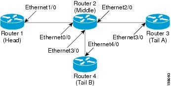
The four-router network in Figure 1 contains the configurations for the examples shown in the following sections:
•
•
Figure 1 Sample Network with an Interface-Based Receiver Proxy Configured
Configuring a Receiver Proxy (Listener) on a Middle Router on Behalf of Tailend Routers
The following example configures a receiver proxy, also called a listener, on the middle router (Router 2) on behalf of the two tailend routers (Routers 3 and 4):
Router# configure terminalEnter configuration commands, one per line. End with CNTL/Z.Router(config)# interface gigabitEthernet 2/0/0Router(config-if)# ip rsvp listener outbound replyRouter(config-if)# exitRouter(config)# interface gigabitethernet 3/0/0Router(config-if)# ip rsvp listener outbound rejectRouter(config-if)# endConfiguring PATH Messages from a Headend Router to Tailend Routers to Test the Receiver Proxy
Note
The following example configures four PATH messages from the headend router (Router 1) to the tailend routers (Routers 3 and 4):
Router# configure terminalEnter configuration commands, one per line. End with CNTL/Z.Router(config)# ip rsvp sender-host 10.0.0.5 10.0.0.1 TCP 2 2 100 10Router(config)# ip rsvp sender-host 10.0.0.5 10.0.0.1 UDP 1 1 100 10Router(config)# ip rsvp sender-host 10.0.0.7 10.0.0.1 TCP 4 4 100 10Router(config)# ip rsvp sender-host 10.0.0.7 10.0.0.1 UDP 3 3 100 10Router(config)# endExamples: Verifying RSVP Interface-Based Receiver Proxy
This section contains the following verification examples:
•
•
•
•
Verifying the PATH Messages in the Database
The following example verifies that the PATH messages you configured are in the database:
Router# show ip rsvp senderTo From Pro DPort Sport Prev Hop I/F BPS10.0.0.5 10.0.0.1 TCP 2 2 none none 100K10.0.0.5 10.0.0.1 UDP 1 1 none none 100K10.0.0.7 10.0.0.1 TCP 4 4 none none 100K10.0.0.7 10.0.0.1 UDP 3 3 none none 100KThe following example verifies that a PATH message has been terminated by a receiver proxy configured to reply.
Note
Router# show ip rsvp sender detailPATH:Destination 10.0.0.5, Protocol_Id 17, Don't Police , DstPort 1Sender address: 10.0.0.1, port: 1Path refreshes:arriving: from PHOP 10.1.2.1 on Et0/0 every 30000 msecsTraffic params - Rate: 100K bits/sec, Max. burst: 10K bytesMin Policed Unit: 0 bytes, Max Pkt Size 2147483647 bytesPath ID handle: 01000402.Incoming policy: Accepted. Policy source(s): DefaultStatus: Proxy-terminatedOutput on Ethernet2/0. Policy status: NOT Forwarding. Handle: 02000401Policy source(s):Path FLR: Never repairedVerifying the Running Configuration
The following example verifies the configuration for GigabitEthernet interface 2/0/0:
Router# show running-config interface gigbitEthernet 2/0/0Building configuration...Current configuration : 132 bytes!interface gigabitEthernet2/0/0ip address 172.16.0.1 255.0.0.0no cdp enableip rsvp bandwidth 2000ip rsvp listener outbound replyendThe following example verifies the configuration for GigabitEthernet interface 3/0/0:
Router# show running-config interface gigbitEthernet 3/0/0Building configuration...Current configuration : 133 bytes!interface gigabitEthernet3/0/0ip address 172.16.0.2 255.0.0.0no cdp enableip rsvp bandwidth 2000ip rsvp listener outbound rejectendVerifying the Listeners (Proxies)
The following example verifies the listeners (proxies) that you configured on the middle router (Router 2) on behalf of the two tailend routers (Routers 3 and 4):
Router# show ip rsvp listenerTo Protocol DPort Description Action OutIf10.0.0.0 0 0 RSVP Proxy reply Et2/010.0.0.0 0 0 RSVP Proxy reject Et3/0Verifying the Reservations
The following example displays reservations established by the middle router (Router 2) on behalf of the tailend routers (Routers 3 and 4) as seen from the headend router (Router 1):
Router# show ip rsvp reservationTo From Pro DPort Sport Next Hop I/F Fi Serv BPS10.0.0.7 10.0.0.1 TCP 4 4 10.0.0.2 Gi1/0 FF RATE 100K10.0.0.7 10.0.0.1 UDP 3 3 10.0.0.2 Gi1/0 FF RATE 100KThe following example verifies that a reservation is locally generated (proxied). Only one reservation is shown:
Router# show ip rsvp reservation detailRSVP Reservation. Destination is 10.0.0.7, Source is 10.0.0.1,Protocol is UDP, Destination port is 1, Source port is 1Next Hop: 10.2.3.3 on GigabitEthernet2/0/0Reservation Style is Fixed-Filter, QoS Service is Guaranteed-RateResv ID handle: 01000405.Created: 09:24:24 EST Fri Jun 2 2006Average Bitrate is 100K bits/sec, Maximum Burst is 10K bytesMin Policed Unit: 0 bytes, Max Pkt Size: 0 bytesStatus: ProxiedPolicy: Forwarding. Policy source(s): DefaultVerifying CAC on an Outbound Interface
The following example verifies that the proxied reservation performed CAC on the local outbound interface:
Router# show ip rsvp installedRSVP: GigabitEthernet2/0/0 has no installed reservationsRSVP: GigabitEthernet3/0/0BPS To From Protoc DPort Sport100K 10.0.0.7 10.0.0.1 UDP 1 1Additional References
The following sections provide references related to the RSVP Interface-Based Receiver Proxy feature.
Related Documents
QoS commands: complete command syntax, command modes, command history, defaults, usage guidelines, and examples
QoS configuration tasks related to RSVP
"Configuring RSVP" module
Internet draft
RSVP Proxy Approaches, Internet draft, October 2006 [draft-lefaucheur-tsvwg-rsvp-proxy-00.txt]
Standards
No new or modified standards are supported by this feature, and support for existing standards has not been modified by this feature.
—
MIBs
RFCs
Technical Assistance
Feature Information for RSVP Interface-Based Receiver Proxy
Table 1 lists the release history for this feature.
Use Cisco Feature Navigator to find information about platform support and software image support. Cisco Feature Navigator enables you to determine which software images support a specific software release, feature set, or platform. To access Cisco Feature Navigator, go to http://www.cisco.com/go/cfn. An account on Cisco.com is not required.
Note
Glossary
flow—A stream of data traveling between two endpoints across a network (for example, from one LAN station to another). Multiple flows can be transmitted on a single circuit.
PE router—provider edge router. A router that is part of a service provider's network and is connected to a customer edge (CE) router.
proxy—A component of RSVP that manages all locally originated and terminated state.
receiver proxy—A configurable feature that allows a router to proxy RSVP RESV messages for local or remote destinations.
RSVP—Resource Reservation Protocol. A protocol for reserving network resources to provide quality of service guarantees to application flows.
set-top box—A computer that acts as a receiver and decodes the incoming signal from a satellite dish, a cable network, or a telephone line.
Cisco and the Cisco Logo are trademarks of Cisco Systems, Inc. and/or its affiliates in the U.S. and other countries. A listing of Cisco's trademarks can be found at www.cisco.com/go/trademarks. Third party trademarks mentioned are the property of their respective owners. The use of the word partner does not imply a partnership relationship between Cisco and any other company. (1005R)
Any Internet Protocol (IP) addresses and phone numbers used in this document are not intended to be actual addresses and phone numbers. Any examples, command display output, network topology diagrams, and other figures included in the document are shown for illustrative purposes only. Any use of actual IP addresses or phone numbers in illustrative content is unintentional and coincidental.
© 2006-2010 Cisco Systems, Inc. All rights reserved.