Downloads |
 Feedback Feedback
|
Table Of Contents
Configuring the RSVP FLR Wait Time
Configuring the RSVP FLR Repair Rate
Configuring the RSVP FLR Notifications
Verifying the RSVP FLR Configuration
Configuration Examples for RSVP FLR
Example: Verifying the RSVP FLR Configuration
Verifying the Details for FLR Procedures
Verifying Configuration Details for a Specific Interface
Verifying Configuration Details Before, During, and After an FLR Procedure
Feature Information for RSVP FLR
RSVP Fast Local Repair
First Published: February 19, 2007Last Updated: February 26, 2010The RSVP Fast Local Repair feature provides quick adaptation to routing changes occurring in global and Virtual Routing and Forwarding (VRF) domains, without the overhead of the refresh period to guarantee the quality of service (QoS) for data flows. With fast local repair (FLR), Resource Reservation Protocol (RSVP) speeds up its response to routing changes from 30 seconds to a few seconds.
Finding Feature Information
Your software release may not support all the features documented in this module. For the latest feature information and caveats, see the release notes for your platform and software release. To find information about the features documented in this module, and to see a list of the releases in which each feature is supported, see the "Feature Overview of RSVP FLR" section.
Use Cisco Feature Navigator to find information about platform support and software image support. To access Cisco Feature Navigator, go to http://www.cisco.com/go/cfn. An account on Cisco.com is not required.
Contents
•
Configuration Examples for RSVP FLR
•
Prerequisites for RSVP FLR
You must configure RSVP on one or more interfaces on at least two neighboring routers that share a link within the network.
Restrictions for RSVP FLR
•
•
•
Information About RSVP FLR
To use the RSVP FLR feature, you should understand the following concepts:
Feature Overview of RSVP FLR
RSVP FLR provides for dynamic adaptation when routing changes occur in global or VRF routing domains. When a route changes, the next PATH and RESV message refreshes establish path and reservation states along the new route. Depending on the configured refresh interval, this reroute happens in tens of seconds. However, during this time, the QoS of flows is not guaranteed because congestion may occur while data packets travel over links where reservations are not yet in place.
In order to provide faster adaptation to routing changes, without the overhead of a refresh period, RSVP registers with the Routing Information Base (RIB) and receives notifications when routes change, thereby triggering state refreshes for the affected destinations. These triggered refreshes use the new route information and, as a result, install reservations over the new path.
When routes change, RSVP has to reroute all affected paths and reservations. Without FLR, the reroute happens when refresh timers expire for the path states. With real-time applications such as VoIP and video on demand (VoD), the requirement changes and the reroute must happen, within three seconds from the triggering event such as link down or link up.
Figure 1 illustrates the FLR process.
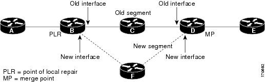
Figure 1 Overview of RSVP FLR
Initial RSVP states are installed for an IPv4 unicast flow over Routers A, B, C, D, and E. Router A is the source or headend, and Router E is the destination or tailend. The data packets are destined to an address of Router E. Assume that a route change occurs, and the new path taken by the data packets is from Router A to Router B to Router F to Router D to Router E; therefore, the old and new paths differ on the segments between Routers B and D. The Router B to Router C to Router D segment is the old segment, and the Router B to Router F to Router D segment is the new segment.
A route may change because of a link or node failure, or if a better path becomes available.
RSVP at Router B detects that the route change affects the RSVP flow and initiates the FLR procedure. The node that initiates an FLR repair procedure, Router B in Figure 1, is the point of local repair (PLR). The node where the new and old segments meet, Router D in Figure 1, is the merge point (MP). The interfaces at the PLR and the MP that are part of the old segment are the old interfaces, and the interfaces that are part of the new segment are the new interfaces.
If a route has changed because of a failure, the PLR may not be the node that detects the failure. For example, it is possible that the link from Router C to Router D fails, and although Router C detects the failure, the route change at Router B is the trigger for the FLR procedure. Router C, in this case, is also referred to as the node that detects the failure.
The support for FLR in VRF domains means that RSVP can get a route change notification, even if there is a route change in any VRF domains, because RSVP FLR was previously supported only in the global routing domain.
Benefits of RSVP FLR
Faster Response Time to Routing Changes
FLR reduces the time that it takes for RSVP to determine that a physical link has gone down and that the data packets have been rerouted. Without FLR, RSVP may not recognize the link failure for 30 seconds when all of the sessions are impacted by having too much traffic for the available bandwidth. With FLR, this time can be significantly reduced to a few seconds.
After detecting the failure, RSVP recomputes the admission control across the new link. If the rerouted traffic fits on the new link, RSVP reserves the bandwidth and guarantees the QoS of the new traffic.
If admission control fails on the new route, RSVP does not explicate tear down the flow, but instead sends a RESVERROR message toward the receiver. If a proxy receiver is running, then RSVP sends a PATHERROR message toward the headend, in response to the RESVERROR message, indicating the admission failure. In both cases, with and without a proxy receiver, the application tears down the failed session either at the headend or at the final destination.
Until this happens, the data packets belonging to this session still flow over the rerouted segment although admission has failed and QoS is affected.
The support of FLR in VRF domains means that if there is a route change in any routing domain, RSVP can use FLR to adapt to the routing change, because RSVP FLR was previously supported only in the global routing domain.
How to Configure RSVP FLR
You can configure the RSVP FLR parameters in any order that you want.
This section contains the following procedures:
•
•
•
•
Configuring the RSVP FLR Wait Time
SUMMARY STEPS
1.
2.
3.
4.
5.
6.
DETAILED STEPS
Configuring the RSVP FLR Repair Rate
SUMMARY STEPS
1.
2.
3.
4.
DETAILED STEPS
Configuring the RSVP FLR Notifications
Perform this task to configure the number of RSVP FLR notifications.
SUMMARY STEPS
1.
2.
3.
4.
DETAILED STEPS
Verifying the RSVP FLR Configuration
Perform this task to verify the RSVP FLR configuration. You can use these commands in any order.
Note
SUMMARY STEPS
1.
2.
3.
4.
5.
6.
DETAILED STEPS
Configuration Examples for RSVP FLR
•
•
Example: Configuring RSVP FLR
The configuration options for RSVP FLR are the following:
•
•
•
Note
Configuring the Wait Time
The following example configures gigabitEthernet interface 0/0/0 with a bandwidth of 200 kbps and a wait time of 1000 ms:
Router# configure terminalEnter configuration commands, one per line. End with CNTL/Z.Router(config)# interface gigabitethernet 0/0/0Router(config-if)# ip rsvp bandwidth 200Router(config-if)# ip rsvp signalling fast-local-repair wait-time 1000Router(config-if)# endConfiguring the Number of Notifications
The following example configures the number of flows that are repaired before suspending to 100:
Router# configure terminalEnter configuration commands, one per line. End with CNTL/Z.Router(config)# ip rsvp signalling fast-local-repair notifications 100Router(config)# exitConfiguring the Repair Rate
The following example configures a repair rate of 100 messages per second:
Router# configure terminalEnter configuration commands, one per line. End with CNTL/Z.Router(config)# ip rsvp signalling fast-local-repair rate 100Router(config)# exitExample: Verifying the RSVP FLR Configuration
This section contains the following examples:
•
•
•
Verifying the Details for FLR Procedures
The following example displays detailed information about FLR procedures:
Router# show ip rsvp signalling fast-local-repair statistics detailFast Local Repair: enabledMax repair rate (paths/sec): 10Max processed (paths/run): 10FLR Statistics:FLR 1: DONEStart Time: 05:18:54 IST Mon Nov 5 2007Number of PSBs repaired: 2Used Repair Rate (msgs/sec): 10RIB notification processing time: 0(us).Time of last PSB refresh: 5025(ms).Time of last Resv received: 6086(ms).Time of last Perr received: 0(us).Suspend count: 0FLR Pacing Unit: 100 msec.Affected neighbors:Nbr Address Interface Relative Delay Values (msec) VRF10.1.2.12 Et0/3 [5000 ,..., 5000 ] vrf110.1.2.12 Et1/3 [5000 ,..., 5000 ] vrf2Verifying Configuration Details for a Specific Interface
The following example from the show ip rsvp interface detail command displays detailed information, including FLR, for the gigabitEthernet 0/0/0 interface:
Router# show ip rsvp interface detail gigabitethernet 0/0/0Et1/0:RSVP: EnabledInterface State: UpBandwidth:Curr allocated: 9K bits/secMax. allowed (total): 300K bits/secMax. allowed (per flow): 300K bits/secMax. allowed for LSP tunnels using sub-pools (pool 1): 0 bits/secSet aside by policy (total): 0 bits/secTraffic Control:RSVP Data Packet Classification is ON via CEF callbacksSignalling:DSCP value used in RSVP msgs: 0x30Number of refresh intervals to enforce blockade state: 4FLR Wait Time (IPv4 flows):Repair is delayed by 1000 msec.Authentication: disabledKey chain: <none>Type: md5Window size: 1Challenge: disabledHello Extension:State: DisabledVerifying Configuration Details Before, During, and After an FLR Procedure
The following is sample output from the show ip rsvp sender detail command before an FLR procedure has occurred:
Router# show ip rsvp sender detailPATH:Destination 192.168.101.21, Protocol_Id 17, Don't Police , DstPort 1Sender address: 10.10.10.10, port: 1Path refreshes:arriving: from PHOP 172.3.31.34 on Et0/0 every 30000 msecsTraffic params - Rate: 9K bits/sec, Max. burst: 9K bytesMin Policed Unit: 0 bytes, Max Pkt Size 2147483647 bytesPath ID handle: 01000401.Incoming policy: Accepted. Policy source(s): DefaultStatus:Output on gigabitEthernet 0/0/0. Policy status: Forwarding. Handle: 02000400Policy source(s): DefaultPath FLR: Never repairedThe following is sample output from the show ip rsvp sender detail command at the PLR during an FLR procedure:
Router# show ip rsvp sender detailPATH:Destination 192.168.101.21, Protocol_Id 17, Don't Police , DstPort 1Sender address: 10.10.10.10, port: 1Path refreshes:arriving: from PHOP 172.16.31.34 on Et0/0 every 30000 msecsTraffic params - Rate: 9K bits/sec, Max. burst: 9K bytesMin Policed Unit: 0 bytes, Max Pkt Size 2147483647 bytesPath ID handle: 01000401.Incoming policy: Accepted. Policy source(s): DefaultStatus:Path FLR: PSB is currently being repaired...try laterPLR - Old Segments: 1Output on Ethernet1/0, nhop 172.5.36.34Time before expiry: 2 refreshesPolicy status: Forwarding. Handle: 02000400Policy source(s): DefaultThe following is sample output from the show ip rsvp sender detail command at the MP during an FLR procedure:
Router# show ip rsvp sender detailPATH:Destination 192.168.101.21, Protocol_Id 17, Don't Police , DstPort 1Sender address: 10.10.10.10, port: 1Path refreshes:arriving: from PHOP 172.16.37.35 on Et1/0 every 30000 msecsTraffic params - Rate: 9K bits/sec, Max. burst: 9K bytesMin Policed Unit: 0 bytes, Max Pkt Size 2147483647 bytesPath ID handle: 09000406.Incoming policy: Accepted. Policy source(s): DefaultStatus: Proxy-terminatedPath FLR: Never repairedMP - Old Segments: 1Input on Serial2/0, phop 172.16.36.35Time before expiry: 9 refreshesThe following is sample output from the show ip rsvp sender detail command at the PLR after an FLR procedure:
Router# show ip rsvp sender detailPATH:Destination 192.168.101.21, Protocol_Id 17, Don't Police , DstPort 1Sender address: 10.10.10.10, port: 1Path refreshes:arriving: from PHOP 172.16.31.34 on Et0/0 every 30000 msecsTraffic params - Rate: 9K bits/sec, Max. burst: 9K bytesMin Policed Unit: 0 bytes, Max Pkt Size 2147483647 bytesPath ID handle: 05000401.Incoming policy: Accepted. Policy source(s): DefaultStatus:Output on Serial3/0. Policy status: Forwarding. Handle: 3B000406Policy source(s): DefaultPath FLR: Started 12:56:16 EST Thu Nov 16 2006, PSB repaired 532(ms) after.Resv/Perr: Received 992(ms) after.Additional References
The following sections provide references related to the RSVP FLR feature.
Related Documents
Standards
No new or modified standards are supported by this feature, and support for existing standards has not been modified by this feature.
—
MIBs
RFCs
RFC 2205
Resource ReSerVation Protocol—Version 1 Functional Specification
RFC 2209
Resource ReSerVation Protocol—Version 1 Messaging Processing Rules
Technical Assistance
Feature Information for RSVP FLR
Table 1 lists the release history for this feature.
Use Cisco Feature Navigator to find information about platform support and software image support. Cisco Feature Navigator enables you to determine which software images support a specific software release, feature set, or platform. To access Cisco Feature Navigator, go to http://www.cisco.com/go/cfn. An account on Cisco.com is not required.
Note
Glossary
admission control—The process by which an RSVP reservation is accepted or rejected on the basis of end-to-end available network resources.
bandwidth—The difference between the highest and lowest frequencies available for network signals. The term is also used to describe the rated throughput capacity of a given network medium or protocol.
message pacing—A system for managing volume and timing that permits messages from multiple sources to be spaced apart over time. RSVP message pacing maintains, on an outgoing basis, a count of the messages that it has been forced to drop because the output queue for the interface used for the message pacing was full.
MP—merge point. The node where the new and old FLR segments meet.
PLR—point of local repair. The node that initiates an FLR procedure.
QoS—quality of service. A measure of performance for a transmission system that reflects its transmission quality and service availability.
RSVP—Resource Reservation Protocol. A protocol that supports the reservation of resources across an IP network. Applications running on IP end systems can use RSVP to indicate to other nodes the nature (bandwidth, jitter, maximum burst, and so on) of the packet streams that they want to receive.
VRF—virtual routing and forwarding. VRF is a VPN routing and forwarding instance. A VRF consists of an IP routing table, a derived forwarding table, a set of interfaces that use the forwarding table, and a set of rules and routing protocols that determine what goes into the forwarding table. In general, a VRF includes the routing information that defines a customer VPN site that is attached to a PE router.
Cisco and the Cisco Logo are trademarks of Cisco Systems, Inc. and/or its affiliates in the U.S. and other countries. A listing of Cisco's trademarks can be found at www.cisco.com/go/trademarks. Third party trademarks mentioned are the property of their respective owners. The use of the word partner does not imply a partnership relationship between Cisco and any other company. (1005R)
Any Internet Protocol (IP) addresses and phone numbers used in this document are not intended to be actual addresses and phone numbers. Any examples, command display output, network topology diagrams, and other figures included in the document are shown for illustrative purposes only. Any use of actual IP addresses or phone numbers in illustrative content is unintentional and coincidental.
© 2007-2010 Cisco Systems, Inc. All rights reserved