Feedback Feedback
|
Table Of Contents
Mobile Ad Hoc Networks for Router-to-Radio Communications
Prerequisites for Mobile Ad Hoc Networks for Router-to-Radio Communications
Restrictions for Mobile Ad Hoc Networks for Router-to-Radio Communications
Information About Mobile Ad Hoc Networks for Router-to-Radio Communications
MANETs for Router-to-Radio Communications
PPPoE Interfaces for Mobile Radio Communications
Link Quality Metrics Reporting for OSPFv3 and EIGRP with VMI Interfaces
OSPF Cost Calculation for VMI Interfaces
EIGRP Cost Metrics for VMI Interfaces
VMI Metric to EIGRP Metric Conversion
Dynamic Cost Metric for VMI Interfaces
EIGRP Metric Dampening for VMI Interfaces
Neighbor Up/Down Signaling for OSFPv3 and EIGRP
PPPoE Credit-based Flow Control
Restrictions for IPv6 Addressing
Multicast Support for VMI Interfaces
How to Configure Router-to-Radio Links Using VMI PPPoE
Implementing the VMI Infrastructure Using PPPoE
Creating a Subscriber Profile for PPPoE Service Selection
Configuring the PPPoE Profile for PPPoE Service Selection
Configuring PPPoE on an Ethernet Interface
Implementing the VMI and Configuring the Routing Protocol
Creating and Configuring a Virtual Template for VMI PPPoE
Creating and Configuring a VMI Interface for EIGRP IPv4
Creating and Configuring a VMI interface for EIGRP IPv6
Setting the EIGRP Change-based Dampening Interval for VMI Interfaces
Setting the EIGRP Interval-based Dampening Interval for VMI Interfaces
Enabling Multicast Support on a VMI Interface
Creating and Configuring a VMI Interface for OSPFv3
Verifying the OSPF Cost Dynamic for a VMI Interface
Verifying the VMI Configuration
Configuration Examples for VMI PPPoE
Basic VMI PPPoE Configuration with EIGRP IPv4: Example
Basic VMI PPPoE Configuration Using EIGRP for IPv6: Example
VMI PPPoE Configuration Using EIGRP for IPv4 and IPv6: Example
EIGRP Metric Dampening for VMI Interfaces: Examples
EIGRP Change-based Dampening for VMI Interfaces: Example
EIGRP Interval-based Dampening for VMI Interfaces: Example
VMI PPPoE Configuration for OSPFv3: Example
VMI PPPoE Configuration Using Multiple Virtual Templates: Example
Enabling Multicast Support on a VMI Interface: Example
Marking and Queuing Packets over VMI: Example
Commands Created or Modified for thie Feature.
Feature Information About the Mobile Ad Hoc Networks for Router-to-Radio Communications
Mobile Ad Hoc Networks for Router-to-Radio Communications
First Published: May 17, 2007
Last Updated: June 29, 2007Mobile Ad Hoc Networks (MANET) for router-to-radio communications address the challenges faced when merging IP routing and mobile radio communications in ad hoc networking applications. the Cisco solution for MANETs provides capabilities that enable
•
Optimal route selection based on Layer 2 feedback from the radio network
•
•
•
Through the router-to-radio link, the radio can inform the router immediately when a node joins or leaves, and this enables the router to recognize topology changes more quickly than if it had to rely on timers. Without this link-status notification from the radio, the router would likely time out while waiting for traffic. The link-status notification from the radio enables the router to respond faster to network topology changes. Metric information regarding the quality of a link is passed between the router and radio, enabling the router to more intelligently decide on which link to use.
With the link-status signaling provided by the router-to-radio link, applications such voice and video work better because outages caused by topology changes are reduced or eliminated. Sessions are more stable and remain active longer.
Key features of Cisco's mobile ad hoc networks for router-to-radio communications include the following:
Link Quality Metrics Reporting
The PPPoE protocol has been extended to enable a router or radio to query or report link-quality metric information. Cisco routers have been enhanced so that OSPFv3 or EIGRP routing protocols can factor link quality metrics into route cost calculations.
Neighbor Up or Down Signaling
Neighbor up or down signaling enables Cisco routers to use link establishment or termination signals from the radio to update routing topology.
PPPoE Credit-based Flow Control
This extension to the PPPoE protocol allows a receiver to control the rate at which a sender can transmit data for each PPPoE session, so that the need for queuing in the radio is minimized.
Virtual Multipoint Interface (VMI)
This Cisco router enhancement maps multiple PPPoE sessions (each representing a point-to-point neighbor connection) into a single broadcast-capable, multi-access interface.
Finding Feature Information in This Module
Your Cisco IOS software release may not support all of the features documented in this module. To reach links to specific feature documentation in this module and to see a list of the releases in which each feature is supported, use the ""Commands Created or Modified for thie Feature." section.
Finding Support Information for Platforms and Cisco IOS and Catalyst OS Software Images
Use Cisco Feature Navigator to find information about platform support and Cisco IOS and Catalyst OS software image support. To access Cisco Feature Navigator, go to http://www.cisco.com/go/cfn. An account on Cisco.com is not required.
Contents
•
•
•
•
•
•
Prerequisites for Mobile Ad Hoc Networks for Router-to-Radio Communications
The features described in this document require one of the following router platforms:
•
•
•
To use the PPPoE and virtual multipoint interface (VMI) features described in this document, a radio device that implements the PPPoE functionality enhancements described in the draft RFC 2516 is required. Users can optionally implement draft-bberry-pppoe-credit-06.txt for PPP Over Ethernet (PPPoE) Extensions for Credit Flow and Link Metrics, but this draft must be implemented if you plan to use VMI features.
Restrictions for Mobile Ad Hoc Networks for Router-to-Radio Communications
VMI on Routed Ports
VMIs can be configured only on routed ports. VMIs are not supported on VLAN or switched ports.
Quality of Service
Of the Quality of Service (QoS) queueing features available from Cisco, only class-based Weighted Fair Queueing (WFQ) is supported on VMIs. The VMI can identify Differentiated Services Code Point (DSCP) values, and perform network-based application recognition (NBAR), but no policing or policy mapping occurs on those matches.
Information About Mobile Ad Hoc Networks for Router-to-Radio Communications
This section describes VMI PPPoE. The following sections are included:
•
•
•
Benefits of Router-to-Radio Links Using Virtual Multipoint Interfaces with PPPoE in Cisco IOS Software
As the global leader in mission-critical networking and IP communications, Cisco is uniquely positioned to deliver reliable and efficient converged voice, video, and data solutions to organizations around the world. Benefits of this technology include the following:
•
•
•
•
MANETs for Router-to-Radio Communications
Mobile Ad Hoc Networks (MANETs) enable users deployed in areas with no fixed communications infrastructure to access critical voice, video, and data services. Soldiers in the field can employ unified communications, multimedia applications, and real-time information dissemination to improve situational awareness and respond quickly to changing battlefield conditions. Disaster managers can use video conferences, database access, and collaborative tools to coordinate multi-agency responses within an Incident Command System (ICS) framework. For event planners and trade show managers, MANETs represent a cost-effective way to accommodate mobile end users on a short term basis. MANETs set the stage for more timely information sharing and faster, more effective decision-making.
In MANET environments, highly mobile nodes communicate with each other across bandwidth-constrained radio links. An individual node includes both a radio and a network router, with the two devices interconnected over an Ethernet. Since these nodes can rapidly join or leave the network, MANET routing topologies are highly dynamic. Fast convergence in a MANET becomes a challenge because the state of a node can change well before the event is detected by the normal timing mechanisms of the routing protocol.
Radio link quality in a MANET can vary dramatically because it can be affected by a variety of factors such as noise, fading, interference, and power fluctuation. As a result, avoiding congestion and determining optimal routing paths also pose significant challenges for the router network. Finally, directional radios that operate on a narrow beam tend to model the network as a series of physical point-to-point connections with neighbor nodes. This point-to-point model does not translate gracefully to multi-hop, multipoint router environments, as it increases the size of each router's topology database and reduces routing efficiency.
Effective networking in a MANET environment therefore requires mechanisms by which
•
•
•
•
PPPoE Interfaces for Mobile Radio Communications
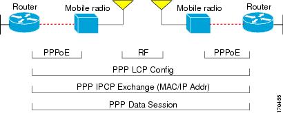
The Cisco MANET solution employs PPP-over-Ethernet (PPPoE) sessions to enable intra-nodal communications between a router and its partner radio. Each radio initiates the PPPoE session as soon as the radio establishes a radio link to another radio. After the PPPoE sessions are active, a PPP session is established end-to-end (router-to-router); This is duplicated each time a radio establishes a new radio link. The Virtual Multipoint Interface (VMI) on the router aggregates multiple PPPoE sessions and multiplexes these to look like a single interface to the routing processes. This interface collects the series of PPP/PPPoE connections. Underneath the VMI interface there are virtual access interfaces that are associated with each of the PPP/PPPoE connections.
A PPPoE session is established between a router and a radio on behalf of every other router/radio neighbor located in the MANET. These Layer 2 sessions are the means by which radio network status gets reported to the Layer 3 processes in the router. Figure 1 illustrates the PPPoE session exchange between mobile routers and directional radios in a MANET network.
Figure 1 PPPoE Session Exchange Between Mobile Routers and Directional Radios
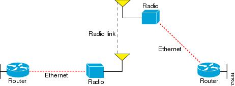
This capability assumes that a PPPoE-equipped radio connects to a router using Ethernet. The router always considers the Ethernet link to be up. If the radio side of the link goes down, the router will wait until a routing update time-out has occurred to declare the route down and then update the routing table. Figure 2 illustrates a simple router-to-radio link topology.
Figure 2 Router-to-Radio Link
Routing protocols used for VMI PPPoE are EIGRP (IPv4, IPv6) and OSPFv3 (IPv6).
Virtual Multipoint Interface
The VMI interface provides services that map outgoing packets to the appropriate PPPoE sessions based on the next-hop forwarding address for that packet. The VMI interface also provides a broadcast service that emulates a set of point-to-point connections as a point-to-multipoint interface with broadcast ability. When a packet with a multicast address is forwarded through the VMI interface, VMI replicates the packet and unicasts it to each of its neighbors.
Directional radios are frequently used in applications that require greater bandwidth, increased power-to-transmission range, or reduced probability of detection. These radios operate in a point-to-point mode, and generally have no broadcast capability. On the other hand, the routing processes in Cisco's MANET solution operate most efficiently when viewing the network link as point-to-multipoint, with broadcast capability. For the router, modeling the MANET as a collection of point-to-point nodes would have a dramatic impact on the size of its internal database.
The Virtual Multipoint Interface (VMI) within the router aggregates all of the per-neighbor PPPoE sessions from the Radio Ethernet connection. The VMI maps the sessions to appear to Layer 3 routing protocols and applications as a single point-to-multipoint, multi-access, broadcast-capable network. However, the VMI preserves the integrity of the PPPoE sessions on the radio side, so that each point-to-point connection can have its own Quality of Service (QoS) queue.
The VMI also relays the link quality metric and neighbor up/down signaling from the radio to the routing protocols. Currently, VMI signals are used by EIGRP (for IPv4 and IPv6 neighbors) and OSPFv3 (for IPv6 neighbors).
Link Quality Metrics Reporting for OSPFv3 and EIGRP with VMI Interfaces
The quality of a radio link has a direct impact on the throughput that can be achieved by router-router traffic. The PPPoE protocol has been extended to provide a process by which a router can request, or a radio can report, link quality metric information. Cisco's OSFPv3 and EIGRP implementations have been enhanced so that the route cost to a neighbor is dynamically updated based on metrics reported by the radio, thus allowing the best route to be chosen within a given set of radio links.
The routing protocols receive raw radio link data, and compute a composite quality metric for each link. In computing these metrics, the following factors may be considered:
•
•
•
•
•
Metrics can be weighted during the configuration process to emphasize or de-emphasize particular characteristics. For example, if throughput is a particular concern, the current data rate metric could be weighted so that it is factored more heavily into the composite metric. Similarly, a metric that is of no concern can be omitted from the composite calculation.
Link metrics can change rapidly, often by very small degrees, which could result in a flood of meaningless routing updates. In a worst case scenario, the network would be churning almost continuously as it struggled to react to minor variations in link quality. To alleviate this concern, Cisco provides a tunable dampening mechanism that allows the user to configure threshold values. Any metric change that falls below the threshold is ignored.The quality of a connection to a neighbor varies, based on various characteristics of the interface when OSPF or EIGRP is used as the routing protocol. The routing protocol receives dynamic raw radio link characteristics and computes a composite metric that is used to reduce the effect of frequent routing changes.
A tunable hysteresis mechanism allows users to adjust the threshold to the routing changes that occur when the router receives a signal that a new peer has been discovered, or that an existing peer is unreachable. The tunable metric is weighted and is adjusted dynamically to account for the following characteristics:
•
•
•
•
Individual weights can be deconfigured and all weights can be cleared so that the cost is set back to the default value for the interface type. Based on the routing changes that occur, cost can be determined by the application of these metrics. The following sections provide more details about OSPF and EIGRP metrics:
•
•
•
•
•
OSPF Cost Calculation for VMI Interfaces
Because cost components can change rapidly, it might be necessary to dampen the volume of changes to reduce network-wide churn. The recommended values for S2, S3, and S4 are based on network simulations that may reduce the rate of network changes. The recommended value for S1 is zero to eliminate this variable from the route cost calculation.
The overall link cost is computed using the following formula:
Table 1 defines the symbols used in the OSPF cost calculation.
While each network might have unique characteristics that require different settings to optimize actual network performance, these are recommended values intended as a starting point for optimizing a OSPFv3 network. Table 2 lists the recommended value settings for OSPF cost metrics.
Using this formula, the default path costs were calculated as noted in the following list. If these values do not suit your network, you can use your own method of calculating path costs.
•
•
•
•
•
•
•
•
•
•
•
To illustrate these settings, the following example shows how OSPF cost metrics might be defined for a VMI interface:
interface vmi1ipv6 ospf cost dynamic weight throughput 0ipv6 ospf cost dynamic weight resources 29ipv6 ospf cost dynamic weight latency 29ipv6 ospf cost dynamic weight L2-factor 29EIGRP Cost Metrics for VMI Interfaces
When EIGRP is used as the routing protocol, metrics allow EIGRP to respond to routing changes. The link-state metric is advertised as the link cost in the router link advertisement.The reply sent to any routing query will always contain the latest metric information. Exceptions which will result in immediate update being sent:
•
•
•
EIGRP receives dynamic raw radio link characteristics and computes a composite EIGRP metric based on a proprietary formula. To avoid churn in the network as a result of the change in the link characteristics, a tunable dampening mechanism is used.
EIGRP uses the metric weights along with a set of vector metrics to compute the composite metric for local RIB installation and route selections. The EIGRP composite metric is calculated using the formula:
EIGRP Metric = 256*((K1*Bw) + (K2*Bw)/(256-Load) + (K3*Delay)*(K5/(Reliability + K4)))
Table 3 lists the EIGRP vector metrics and their descriptions.
EIGRP monitors metric weights on an interface to allow for the tuning of EIGRP metric calculations and indicate type of service (TOS). Table 4 lists the K-values and their default.
Most configurations use the first two metrics -delay and bandwidth, with bandwidth taking precedence. The default formula of 256*(BW +Delay) is the EIGRP metric. The bandwidth for the formula is scaled and inverted by the following formula:
(10^7/minimum Bw in kilobits per second)
Note
For example, look at an IGRP link whose bandwidth to a particular destination is 128k and the delay is 84000 microseconds.
Using the cut-down formula, the EIGRP metric calculation would simplify to 256*(BW + Delay), resulting in the following value:
Metric = 256*(10^7/128 + 84000/10)= 256*86525 = 22150400
To calculate route delay, divide the delay value by 10 to get the true value in tenths of microseconds
When calcluating the delay for MANET and the delay is obtained from a router interface, it is always calculated in tens of microseconds. In most cases, when using MANET, you will not use the interface delay, but rather the delay that is advertised by the radio. The delay you will receive from the radio is in microseconds, so you must adjust the cut-down formula as follows:
Metric = (256*(10^7/128) + (84000*256)/10) = 20000000 + 2150400 = 22150400
VMI Metric to EIGRP Metric Conversion
The quality of connection to a VMI neighbor will vary based on various characteristics computed dynamically based on the feedback from L2 to L3. Table 5 lists the EIGRP metrics and their significance.
These EIGRP vector metric values map to the basic EIGRP interface parameters as indicated in Table 6
Note
Dynamic Cost Metric for VMI Interfaces
The dynamic cost metric used for interfaces is computed based on the Layer 2 (L2) feedback to Layer 3 (L3). The dynamic cost is calculated using the following formula:
L2L3API
Where the metric calculations are
S1 = ipv6 ospf dynamic weight throughput
S2 = ipv6 ospf dynamic weight resources
S3 = ipv6 ospf dynamic weight latency
S4 = ipv6 ospf dynamic weight L2 factor
OC = standard cost of a non-VMI routeThroughput = (current-data-rate)/(maximum-data-rate)
Router-dynamic cost= OC + (S1) + (S2) + (S3) + (S4)
For a dynamic cost to have the same cost as a default cost, all parameters must equal zero.
Each Layer 2 feedback can contribute a cost in the range of 0 to 65535. To tune down this cost range, use the optional weight keyword in conjunction with the throughput, resources, latency, or L2-factor keyword. Each of these weights has a default value of 100% and can be configured in the range from 0 to 100. When 0 is configured for a specific weight, that weight does not contribute to the Open Shortest Path First (OSPF) cost.
Because cost components can change rapidly, you may need to dampen the amount of changes in order to reduce network-wide churn. Use the optional hysteresis keyword with the threshold threshold-value keyword and argument to set a cost change threshold. Any cost change below this threshold is ignored
EIGRP Metric Dampening for VMI Interfaces
Because metric components could be changing rapidly, the frequency of the changes can have an impact on the network. Frequent changes require that prefixes learned though the VMI interface be updated and sent to all adjacencies. This update can result in further updates and, in a worst-case scenario, cause network-wide churn. To prevent such effects, metrics can be dampened, or thresholds set, so that any change that does not exceed the dampening threshold is ignored.
Network changes that cause an immediate update include
•
•
•
Dampening the metric changes can be configured based on change or time intervals.
If the dampening method is change-based, changes in routes learned though a specific interface, or in the metrics for a specific interface, will not be advertised to adjacencies until the computed metric changes from the last advertised value significantly enough to cause an update to be sent.
If this dampening method is interval-based, changes in routes learned though a specific interface, or in the metrics for a specific interface, will not be advertised to adjacencies until the specified interval is met, unless the change results in a new route path selection.
When the timer expires, any routes, which have outstanding changes to report, will be sent out. If a route changes, such that the final metric of the route matches the last updated metric, no update will be sent.
Neighbor Up/Down Signaling for OSFPv3 and EIGRP
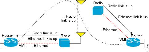
MANETs are highly dynamic environments. Nodes may move into, or out of, radio range at a fast pace. Each time a node joins or leaves, of course, the network topology must be logically reconstructed by the routers. Routing protocols normally use timer-driven "hello" messages or neighbor timeouts to track topology changes, but for MANETs reliance on these mechanisms can result in unacceptably slow convergence.
This signaling capability provides faster network convergence by using link-status signals generated by the radio. The radio notifies the router each time a link to another neighbor is established or terminated by the creation and termination of PPPoE sessions. In the router, the routing protocols (OSPFv3 or EIGRP) respond immediately to these signals by expediting formation of a new adjacency (for a new neighbor) or tearing down an existing adjacency (if a neighbor is lost). For example, if a vehicle drives behind a building and loses its connection, the router will immediately sense the loss and establish a new route to the vehicle through neighbors that are not blocked. This high speed network convergence is essential for minimizing dropped voice calls and disruptions to video sessions.
When VMI with PPPoE is used and a partner node has left or a new one has joined, the radio informs the router immediately of the topology change. Upon receiving the signal, the router immediately declares the change and updates the routing tables.
The signaling capability reduces routing delays and prevents applications from timing out; enables network-based applications and information to be delivered reliably and quickly over directional radio links; provides faster convergence and optimal route selection so that delay-sensitive traffic such as voice and video are not disrupted; and reduces impact on radio equipment by minimizing the need for internal queuing/buffering; also provides consistent Quality of Service for networks with multiple radios.
The messaging allows for flexible rerouting when necessary because of
•
•
•
•
•
Figure 3 illustrates the signaling sequence that occurs when radio links go up and down.
Figure 3 Up and Down Signaling Sequence
PPPoE Credit-based Flow Control
Each radio initiates a PPPoE session with its local router as soon as the radio establishes a link to another radio. Once the PPPoE sessions are active for each node, a PPP session is then established end-to-end (router-to-router). This process is duplicated each time a radio establishes a new link.
The carrying capacity of each radio link may vary due to location changes or environmental conditions, and many radio transmission systems have limited buffering capabilities. To minimize the need for packet queuing in the radio, Cisco has implemented extensions to the PPPoE protocol that enable the router to control traffic buffering in congestion situations. Implementing flow-control on these router-to-radio sessions also will allow use of quality of service features such as fair queuing.
The solution utilizes a credit-granting mechanism documented in an IETF informational draft. When the PPPoE session is established, the radio can request a flow-controlled session. If the router acknowledges the request, all subsequent traffic must be flow-controlled. If a flow control session has been requested and cannot be supported by the router, the session is terminated. Typically, both the radio and the router initially grant credits during session discovery. Once a device exhausts its credits, it must stop sending until additional credits have been granted. Credits can be added incrementally over the course of a session.
IPv6 Addresses
You can configure VMI interfaces with IPv6 addresses only, IPv4 addresses only, or both IPv4 and IPv6 addresses.
IPv6 addresses are assigned to individual router interfaces and enable the forwarding of IPv6 traffic globally on the router. By default, IPv6 addresses are not configured and IPv6 routing is disabled.
Note
The /prefix-length argument in the ipv6 address command is a decimal value that indicates how many of the high-order contiguous bits of the address comprise the prefix (the network portion of the address) A slash mark must precede the decimal value.
Restrictions for IPv6 Addressing
In Cisco IOS Release 12.2(4)T or later releases, Cisco IOS Release 12.0(21)ST, and Cisco IOS Release 12.0(22)S or later releases, the ipv6 address or ipv6 address eui-64 command can be used to configure multiple IPv6 global addresses within the same prefix on an interface. Multiple IPv6 link-local addresses on an interface are not supported.
Prior to Cisco IOS Releases 12.2(4)T, 12.0(21)ST, and 12.0(22)S, the Cisco IOS command-line interface (CLI) displays the following error message when multiple IPv6 addresses within the same prefix on an interface are configured as:
Prefix <prefix-number> already assigned to <interface-type>For additional information about IPv6 addressing, see Implementing IPv6 Addressing in the Cisco IOS IPv6 Configuration Guide at the following URL:
http://www.cisco.com/en/US/products/ps6441/products_configuration_guide_chapter09186a00806f3a6a.html
Multicast Support for VMI Interfaces
VMI interfaces operate, by default, in aggregate mode, which means that all of the virtual-access interfaces created by PPPoE sessions are logically aggregated under the configured VMI. That is, applications above Layer 2, such as, EIGRP and OSPFv3, should be defined on the VMI interface only. Packets sent to the VMI interface will be correctly forwarded to the correct virtual-access interface(s).
If you are running multicast applications that require the virtual-access interfaces to be exposed to applications above Layer 2 directly, you can configure the VMI to operate in bypass mode. Most multicast applications require that the virtual-access interfaces be exposed directly to the routing protocols to insure that that multicast Reverse Path Forwarding (RPF) can operate as expected. When you use the bypass mode, you must define a VMI interface to handle presentation of cross-layer signals such as, neighbor up, neighbor down, and metrics. Applications will be aware of the actual underlying virtual-access interfaces, and will send packets to them directly. Additional information is required on the virtual template configuration. Operating the VMI in bypass mode can cause databases in the applications to be larger than would normally be expected because knowledge of more interfaces is required for normal operation.
After configuring the bypass mode, Cisco recommends that you save the running configuration to NVRAM to override the default mode of operation for VMI to logically aggregate the virtual-access interfaces..
How to Configure Router-to-Radio Links Using VMI PPPoE
This section identifies the tasks that will be used to configure VMI PPPoE. Configuring the VMI PPPoE involves implementing the infrastructure, establishing the IPv4 and IPv6 addressing schemes, and configuring the routing environment. This document contains configuration guidelines only for configuration of PPPoE as it relates to VMIs. For details about configuring PPPoE, refer to the Cisco IOS Broadband and DSL Configuration Guide. For details about PPPoE commands, refer to the Cisco IOS Broadband and DSL Command Reference.
The following sections are included:
•
•
Implementing the VMI Infrastructure Using PPPoE
The PPPoE protocol provides the transport for the mobile network. The following tasks are required to configure PPPoE to support the VMI.
•
•
•
Creating a Subscriber Profile for PPPoE Service Selection
Perform this task to configure a subscriber profile for PPPoE service selection.
SUMMARY STEPS
1.
2.
3.
4.
5.
6.
DETAILED STEPS
What to Do Next
After you have defined the PPPoE subscriber profile and service, you must apply the definitions to a BBA group
Configuring the PPPoE Profile for PPPoE Service Selection
Perform this task to associate a subscriber profile with a PPPoE profile. In this configuration, the BBA group name should match the subscriber profile name previously defined in the subscriber profile. In this case, the profile name used as the service name is manet_radio.
SUMMARY STEPS
1.
2.
3.
4.
5.
6.
DETAILED STEPS
Troubleshooting Tips
Use the show pppoe session and debug pppoe commands to troubleshoot PPPoE sessions.
Configuring PPPoE on an Ethernet Interface
Perform this task to assign a PPPoE profile to an Ethernet interface.
SUMMARY STEPS
1.
2.
3.
4.
5.
DETAILED STEPS
Implementing the VMI and Configuring the Routing Protocol
The configuration guidelines in this section are all optional, depending on the method and routing protocol that you choose to support the VMI interface.
•
•
•
•
•
•
•
•
•
•
Creating and Configuring a Virtual Template for VMI PPPoE
To create and configure a virtual template, use the following commands beginning in global configuration mode. Cisco recommends that, when using the virtual template, you turn off the PPP keepalive messages to make CPU usage more efficient and to help avoid the potential for the router to terminate the connection if PPP keepalive packets are missed over a lossy Radio Frequency (RF) link.
You can configure multiple virtual template interfaces for your VMI PPPoE connections. The selection of which virtual template to use is predicated on the service name sent by the radio during PPPoE session establishment. As an example, consider the following configuration:
subscriber authorization enable!subscriber profile onepppoe service manet_radio_over_x_band!!subscriber profile twopppoe service manet_radio_over_c_band!!!bba-group pppoe onevirtual-template 1service profile one!!bba-group pppoe twovirtual-template 2service profile two!!interface Virtual-Template1...!!interface Virtual-Template2...Using this configuration, any PPPoE request for a session (presentation of a PPPoE Active Discovery Initiate, or PADI packet) with the service name of "manet_radio_over_x_band" would use Virtual-Template1 as the interface to be cloned. Conversely, any PADI presented by the radio with the service name of "manet_radio_over_c_band" would use Virtual-Template2.
Note
SUMMARY STEPS
1.
2.
3.
4.
or
ipv6 enable
or both if both IPv4 and IPv6 are used.DETAILED STEPS
Where To Go Next
Refer to the "Virtual Interface Template Service" chapter in the Cisco IOS Dial Solutions Configuration Guide for additional information about configuring the virtual templates
Creating and Configuring a VMI Interface for EIGRP IPv4
Perform this task to create the VMI interface and associate it with the Ethernet interface on which PPPoE is enabled. When you create a VMI interface, assign the IPv6 or IPv4 address to that VMI interface definition. Do not assign any addresses to the corresponding physical interface.
The radio alerts the router with PADT messages that the layer-2 radio frequency (RF) connection is no longer alive. Cisco recommends that you turn off the PPP keepalive messages to make CPU usage more efficient and to help avoid the potential for the router to terminate the connection if PPP keepalive packets are missed over a lossy RF link.
Note
SUMMARY STEPS
1.
2.
3.
4.
5.
6.
7.
8.
9.
10.
11.
12.
13.
14.
15.
16.
17.
18.
19.
20.
21.
DETAILED STEPS
Creating and Configuring a VMI interface for EIGRP IPv6
Perform this task to create the VMI interface and associate it with the Ethernet interface on which PPPoE is enabled. When you create a VMI interface, assign the IPv6 address to that VMI interface definition. Do not assign any addresses to the corresponding physical interface.
The radio alerts the router with PADT messages that the layer-2 radio frequency (RF) connection is no longer alive. If you turn off the PPP keepalive messages, it can make CPU usage more efficient and help to avoid the potential for the router to terminate the connection if PPP keepalive packets are missed over a lossy RF link.
SUMMARY STEPS
1.
2.
3.
4.
5.
6.
7.
8.
9.
10.
11.
12.
13.
14.
15.
16.
17.
18.
19.
20.
21.
22.
DETAILED STEPS
.
Setting the EIGRP Change-based Dampening Interval for VMI Interfaces
Perform the following tasks to set the change-based dampening interval for VMI interfaces:
This configuration assumes that a virtual template and appropriate PPPoE configurations have already been completed. Refer to theCisco IOS IP Mobility Configuration Guide for VMI configuration details.
This confiruation sets the threshold to 50 percent tolerance routing updates involving VMI interfaces and peers
Note
SUMMARY STEPS
1.
2.
3.
To configure an IPv4 address:
4.
5.
6.
OR-To configure an IPv6 address:
7.
8.
or
ipv6 enable9.
10.
(OR-use both the IPv4 and IPv6 configurations if both IPv4 and IPv6 are used and continue with the following commands:)
11.
12.
13.
DETAILED STEPS
Setting the EIGRP Interval-based Dampening Interval for VMI Interfaces
Perform this task to set an interval-based dampening interval for VMI interfaces.
This configuration assumes that a virtual template and appropriate PPPoE configurations have already been completed. Refer to theCisco IOS IP Mobility Configuration Guide for VMI configuration details.
This configuration sets the interval to 30 seconds at which updates occur for topology changes that affect VMI interfaces and peers:
SUMMARY STEPS
1.
2.
3.
4.
5.
6.
or
ipv6 enable
or both if both IPv4 and IPv6 are used.7.
8.
9.
DETAILED STEPS
Enabling Multicast Support on a VMI Interface
Perform this task to enable bypass mode on a VMI interface and override the default aggregation that occurs on VMI interfaces. This configuration assumes that you have already configured a virtual template and appropriate PPPoE sessions for the VMI interface.
Using bypass mode can cause databases in the applications to be larger because knowledge of more interfaces are required for normal operation.
After you enter the mode bypass command, Cisco recommends that you copy the running configuration to NVRAM because the default mode of operation for VMI is to logically aggregate the virtual-access interfaces.
SUMMARY STEPS
1.
2.
3.
4.
5.
DETAILED STEPS
Creating and Configuring a VMI Interface for OSPFv3
Perform this task to create the VMI interface and associate it with the Ethernet interface on which PPPoE is enabled. When you create a VMI interface, assign the IPv6 or IPv4 address to that VMI interface definition. Do not assign any addresses to the corresponding physical interface.
SUMMARY STEPS
1.
2.
3.
4.
5.
6.
7.
8.
9.
10.
11.
12.
13.
14.
15.
16.
17.
18.
19.
20.
21.
22.
23.
24.
25.
26.
27.
DETAILED STEPS
Verifying the OSPF Cost Dynamic for a VMI Interface
The following shows a sample output display when the OSPF cost dynamic is configured on a VMI.
Router1# show ipv6 ospf interface serial2/0Serial2/0 is up, line protocol is upLink Local Address FE80::A8BB:CCFF:FE00:100, Interface ID 10Area 1, Process ID 1, Instance ID 0, Router ID 200.1.1.1Network Type POINT_TO_MULTIPOINT, Cost: 64 (dynamic), Cost Hysteresis: 200Cost Weights: Throughput 100, Resources 20, Latency 80, L2-factor 100Transmit Delay is 1 sec, State POINT_TO_MULTIPOINT,Timer intervals configured, Hello 30, Dead 120, Wait 120, Retransmit 5Hello due in 00:00:19Index 1/2/3, flood queue length 0Next 0x0(0)/0x0(0)/0x0(0)Last flood scan length is 0, maximum is 0Last flood scan time is 0 msec, maximum is 0 msecNeighbor Count is 0, Adjacent neighbor count is 0Suppress hello for 0 neighbor(s)Verifying the VMI Configuration
Possible commands to use in verifying the configuration include:
•
•
•
•
•
•
•
•
•
Configuration Examples for VMI PPPoE
•
•
•
•
•
•
•
•
•
•
•
Basic VMI PPPoE Configuration with EIGRP IPv4: Example
This example illustrates the simplest configuration using EIGRP as the routing protocol. This configuration includes one VMI interface.
version 12.4service timestamps debug datetime msecservice timestamps log datetime msecno service password-encryption!hostname host1!logging buffered 3000000no logging consoleenable password test!no aaa new-modelclock timezone EST -5ip cef!no ip domain lookupsubscriber authorization enable!subscriber profile host1pppoe service manet_radio!subscriber profile testpppoe service manet_radio!!multilink bundle-name authenticatedno virtual-template subinterface!archivelog config!policy-map FQclass class-defaultfair-queue!bba-group pppoe testvirtual-template 1service profile test!bba-group pppoe VMI1virtual-template 1service profile host1!!interface Loopback1ip address 10.9.1.1 255.255.255.0no ip proxy-arpload-interval 30!interface FastEthernet0/0no ip addressno ip mroute-cacheload-interval 30speed 100full-duplexpppoe enable group VMI1!interface Serial1/0no ip addressno ip mroute-cacheshutdownclock rate 2000000!interface Serial1/1no ip addressno ip mroute-cacheshutdownclock rate 2000000!!interface Serial1/2no ip addressno ip mroute-cacheshutdownclock rate 2000000!interface Serial1/3no ip addressno ip mroute-cacheshutdownclock rate 2000000!interface FastEthernet2/0switchport access vlan 2duplex fullspeed 100!interface FastEthernet2/1switchport access vlan 503load-interval 30duplex fullspeed 100!interface FastEthernet2/2shutdown!interface FastEthernet2/3shutdown!interface Virtual-Template1ip unnumbered vmi1load-interval 30no keepaliveservice-policy output FQ!interface Vlan1no ip addressno ip mroute-cacheshutdown!interface Vlan2ip address 10.15.60.144 255.255.255.0no ip mroute-cacheload-interval 30!interface Vlan503ip address 10.2.2.2 255.255.255.0load-interval 30!interface vmi1ip address 10.3.3.1 255.255.255.0no ip redirectsno ip split-horizon eigrp 1load-interval 30eigrp 1 interface dampening-change 50physical-interface FastEthernet0/0!router eigrp 1redistribute connectednetwork 10.2.0.0 0.0.255.255network 10.3.0.0 0.0.255.255auto-summary!no ip http serverno ip http secure-server!control-plane!!line con 0exec-timeout 0 0stopbits 1line aux 0line vty 0 4login!endBasic VMI PPPoE Configuration Using EIGRP for IPv6: Example
This example shows the basic requirements for configuring a VMI interface that uses EIGRP for IPv6 as the routing protocol. It includes one VMI interface.
version 12.4service timestamps debug datetime msecservice timestamps log datetime msecno service password-encryption!hostname host1!logging buffered 3000000no logging consoleenable password lab!no aaa new-modelclock timezone EST -5ip cef!!!!no ip domain lookupipv6 unicast-routingipv6 cefsubscriber authorization enable!subscriber profile host1pppoe service manet_radio!subscriber profile testpppoe service manet_radio!!multilink bundle-name authenticatedno virtual-template subinterface!!!!archivelog config!!policy-map FQclass class-defaultfair-queue!!!!!bba-group pppoe testvirtual-template 1service profile test!bba-group pppoe VMI1virtual-template 1service profile host1!!!interface Loopback1ip address 10.9.1.1 255.255.255.0no ip proxy-arpload-interval 30ipv6 address 2001:0DB1:1::1/64ipv6 enableipv6 eigrp 1!interface FastEthernet0/0no ip addressno ip mroute-cacheload-interval 30speed 100full-duplexpppoe enable group VMI1!interface Serial1/0no ip addressno ip mroute-cacheshutdownclock rate 2000000!interface Serial1/1no ip addressno ip mroute-cacheshutdownclock rate 2000000!interface Serial1/2no ip addressno ip mroute-cacheshutdownclock rate 2000000!interface Serial1/3no ip addressno ip mroute-cacheshutdownclock rate 2000000!interface FastEthernet2/0switchport access vlan 2duplex fullspeed 100!interface FastEthernet2/1switchport access vlan 503load-interval 30duplex fullspeed 100!interface FastEthernet2/2shutdown!interface FastEthernet2/3shutdown!interface Virtual-Template1no ip addressload-interval 30ipv6 enableno keepaliveservice-policy output FQ!interface Vlan1no ip addressno ip mroute-cacheshutdown!interface Vlan2ip address 10.15.60.144 255.255.255.0no ip mroute-cacheload-interval 30!interface Vlan503ip address 10.2.2.2 255.255.255.0load-interval 30ipv6 address 2001:0DB1:8::1/64ipv6 enableipv6 eigrp 1!interface vmi1no ip addressload-interval 30ipv6 enableno ipv6 redirectsipv6 eigrp 1no ipv6 split-horizon eigrp 1physical-interface FastEthernet0/0!no ip http serverno ip http secure-server!ipv6 router eigrp 1router-id 10.9.1.1no shutdownredistribute connected!control-plane!line con 0exec-timeout 0 0stopbits 1line aux 0line vty 0 4login!endVMI PPPoE Configuration Using EIGRP for IPv4 and IPv6: Example
The following examples shows how to configure VMI PPPoE using EIGRP as the IP routing protocol when you have both IPv4 and IPv6 addresses configured on the interface. This configuration includes one VMI interface.
version 12.4service timestamps debug datetime msecservice timestamps log datetime msecno service password-encryption!hostname host1!logging buffered 3000000no logging consoleenable password lab!no aaa new-modelclock timezone EST -5ip cef!no ip domain lookupipv6 unicast-routingipv6 cefsubscriber authorization enable!subscriber profile host1pppoe service manet_radio!subscriber profile testpppoe service manet_radio!!multilink bundle-name authenticatedno virtual-template subinterface!archivelog config!policy-map FQclass class-defaultfair-queue!bba-group pppoe testvirtual-template 1service profile test!bba-group pppoe VMI1virtual-template 1service profile host1!!interface Loopback1ip address 10.9.1.1 255.255.255.0no ip proxy-arpload-interval 30ipv6 address 2001:0DB1:1::1/64ipv6 enableipv6 eigrp 1!interface FastEthernet0/0no ip addressno ip mroute-cacheload-interval 30speed 100full-duplexpppoe enable group VMI1!interface Serial1/0no ip addressno ip mroute-cacheshutdownclock rate 2000000!interface Serial1/1no ip addressno ip mroute-cacheshutdownclock rate 2000000!interface Serial1/2no ip addressno ip mroute-cacheshutdownclock rate 2000000!interface Serial1/3no ip addressno ip mroute-cacheshutdownclock rate 2000000!interface FastEthernet2/0switchport access vlan 2duplex fullspeed 100!interface FastEthernet2/1switchport access vlan 503load-interval 30duplex fullspeed 100!interface FastEthernet2/2shutdown!interface FastEthernet2/3shutdown!interface Virtual-Template1ip unnumbered vmi1load-interval 30ipv6 enableno keepaliveservice-policy output FQ!interface Vlan1no ip addressno ip mroute-cacheshutdown!interface Vlan2ip address 10.15.60.144 255.255.255.0no ip mroute-cacheload-interval 30!interface Vlan503ip address 10.2.2.2 255.255.255.0load-interval 30ipv6 address 2001:0DB1:8::1/64ipv6 enableipv6 eigrp 1!interface vmi1ip address 10.3.3.1 255.255.255.0no ip redirectsno ip split-horizon eigrp 1load-interval 30ipv6 address 2001:0DB1:2::1/64ipv6 enableno ipv6 redirectsipv6 eigrp 1no ipv6 split-horizon eigrp 1eigrp 1 interface dampening-interval 30physical-interface FastEthernet0/0!router eigrp 1redistribute connectednetwork 10.2.0.0 0.0.255.255network 10.3.0.0 0.0.255.255auto-summary!!!no ip http serverno ip http secure-server!ipv6 router eigrp 1router-id 10.9.1.1no shutdownredistribute connected!control-plane!!line con 0exec-timeout 0 0stopbits 1line aux 0line vty 0 4login!endEIGRP Metric Dampening for VMI Interfaces: Examples
The eigrp interface command advertises routing changes for EIGRP traffic only.
The REPLY sent to any QUERY will always contain the latest metric information. Exceptions which will result in immediate UPDATE being sent:
•
•
•
To prevent network-wide churn from frequent metric changes from impacting the network, even causing network-wide churn, metrics can be dampened, or thresholds set, so that any change that does not exceed the dampening threshold is ignored. The examples in this section show how to set the EIGRP dampening intervals to avoid such impacts.
EIGRP Change-based Dampening for VMI Interfaces: Example
The following example sets the threshold to 50 percent tolerance routing updates involving VMI interfaces and peers:
interface vmi1ip address 10.2.2.1 255.255.255.0ipv6 address 2001:0DB1:2::1/96ipv6 enableeigrp 1 interface dampening-change 50physical-interface Ethernet0/0EIGRP Interval-based Dampening for VMI Interfaces: Example
The following example sets the interval to 30 seconds at which updates occur for topology changes that affect VMI interfaces and peers:
interface vmi1ip address 10.2.2.1 255.255.255.0ipv6 address 2001:0DB1:2::1/96ipv6 enableeigrp 1 interface dampening-interval 30physical-interface Ethernet0/0VMI PPPoE Configuration for OSPFv3: Example
The following example shows how to configure VMI PPPoE using OSPFv3 as the routing protocol. This configuration includes three VMI interfaces.
Building configuration...Current configuration : 3568 bytes!! Last configuration change at 00:03:01 EST Thu Jan 1 2004!version 12.4service timestamps debug datetime msecservice timestamps log datetime msecno service password-encryption!hostname host2!boot-start-markerboot system flash:c3270-adventerprisek9-mz.124-11.3.PI6bboot-end-marker!logging buffered 3000000no logging consoleenable password lab!no aaa new-modelclock timezone EST -5!!ip cef!!no ip domain lookupipv6 unicast-routingipv6 cefsubscriber authorization enable!subscriber profile host2pppoe service manet_radio!!multilink bundle-name authenticatedno virtual-template subinterface!policy-map FQclass class-defaultfair-queue!bba-group pppoe VMI1virtual-template 1service profile host2!bba-group pppoe VMI2virtual-template 2service profile host2!bba-group pppoe VMI3virtual-template 3service profile host2!!interface Loopback1ip address 10.16.1.1 255.255.255.0no ip proxy-arpload-interval 30ipv6 address 2001:0DB1:1::1/64ipv6 enableipv6 ospf 1 area 0!interface FastEthernet0/0no ip addressload-interval 30duplex fullspeed 100pppoe enable group VMI3!interface GigabitEthernet0/0no ip addressload-interval 30duplex fullspeed 100pppoe enable group VMI1!interface FastEthernet0/1no ip addressshutdownduplex autospeed auto!interface GigabitEthernet0/1no ip addressload-interval 30duplex fullspeed 100pppoe enable group VMI2!interface Serial1/0no ip addressshutdown!interface Serial1/1no ip addressshutdown!interface Serial1/2no ip addressshutdownclock rate 2000000!interface Serial1/3no ip addressshutdownclock rate 2000000!interface FastEthernet2/0switchport access vlan 2duplex fullspeed 100!interface FastEthernet2/1switchport access vlan 503load-interval 30duplex fullspeed 100!interface FastEthernet2/2shutdown!interface FastEthernet2/3shutdown!interface Virtual-Template1no ip addressload-interval 30ipv6 enableno keepaliveservice-policy output FQ!interface Virtual-Template2no ip addressload-interval 30ipv6 enableno keepaliveservice-policy output FQ!interface Virtual-Template3no ip addressload-interval 30ipv6 enableno keepaliveservice-policy output FQ!interface Vlan1no ip addressshutdown!interface Vlan2ip address 10.15.60.146 255.255.255.0load-interval 30!interface Vlan503ip address 10.2.2.2 255.255.255.0load-interval 30ipv6 address 2001:0DB1:8::1/64ipv6 enableipv6 ospf 1 area 0!interface vmi1no ip addressload-interval 30ipv6 enableipv6 ospf network point-to-multipointipv6 ospf cost dynamic hysteresis threshold 1000ipv6 ospf cost dynamic weight throughput 0ipv6 ospf cost dynamic weight resources 29ipv6 ospf cost dynamic weight latency 29ipv6 ospf cost dynamic weight L2-factor 29ipv6 ospf 1 area 0physical-interface GigabitEthernet0/0!interface vmi2no ip addressload-interval 30ipv6 enableipv6 ospf network point-to-multipointipv6 ospf cost dynamic hysteresis threshold 1000ipv6 ospf cost dynamic weight throughput 0ipv6 ospf cost dynamic weight resources 29ipv6 ospf cost dynamic weight latency 29ipv6 ospf cost dynamic weight L2-factor 29ipv6 ospf 1 area 0physical-interface GigabitEthernet0/1!interface vmi3no ip addressload-interval 30ipv6 enableipv6 ospf network point-to-multipointipv6 ospf cost dynamic hysteresis threshold 1000ipv6 ospf cost dynamic weight throughput 0ipv6 ospf cost dynamic weight resources 29ipv6 ospf cost dynamic weight latency 29ipv6 ospf cost dynamic weight L2-factor 29ipv6 ospf 1 area 0physical-interface FastEthernet0/0!!!no ip http serverno ip http secure-server!ipv6 router ospf 1router-id 10.16.1.1log-adjacency-changesredistribute connected metric-type 1timers spf 1 1!!!!!control-plane!!line con 0exec-timeout 0 0line aux 0line vty 0 4login!endendVMI PPPoE Configuration Using Multiple Virtual Templates: Example
The following example shows how to configure VMI using multiple virtual templates. This example shows two VMIs, each with a different service name.
version 12.4service timestamps debug datetime msecservice timestamps log datetime msecno service password-encryption!hostname router1!boot-start-markerboot-end-marker!!no aaa new-model!resource policy!clock timezone EST -5ip cefno ip domain lookup!!subscriber authorization enable!subscriber profile router1_groundpppoe service manet_radio_ground!subscriber profile router1_satellitepppoe service manet_radio_satellite!ipv6 unicast-routingpolicy-map FQclass class-defaultfair-queue!!!bba-group pppoe router1_groundvirtual-template 1service profile router1_ground!bba-group pppoe router1_satellitevirtual-template 2service profile router1_satellite!!interface Ethernet0/0pppoe enable group router1_ground!interface Ethernet0/1pppoe enable group router1_satellite!interface Ethernet0/2no ip addressshutdown!interface Ethernet0/3no ip addressshutdown!interface Ethernet1/0no ip addressshutdown!interface Ethernet1/1no ip addressshutdown!interface Ethernet1/2no ip addressshutdown!interface Ethernet1/3no ip addressshutdown!interface Serial2/0no ip addressshutdownserial restart-delay 0!interface Serial2/1no ip addressshutdownserial restart-delay 0!interface Serial2/2no ip addressshutdownserial restart-delay 0!interface Serial2/3no ip addressshutdownserial restart-delay 0!interface Serial3/0no ip addressshutdownserial restart-delay 0!interface Serial3/1no ip addressshutdownserial restart-delay 0!interface Serial3/2no ip addressshutdownserial restart-delay 0!interface Serial3/3no ip addressshutdownserial restart-delay 0!interface Virtual-Template1ip unnumbered vmi1load-interval 30no peer default ip addressno keepaliveservice-policy output FQ!interface Virtual-Template2ip unnumbered vmi1load-interval 30no peer default ip addressno keepaliveservice-policy output FQ!interface vmi1description ground connectionip address 10.2.2.1 255.255.255.0physical-interface Ethernet0/0!interface vmi2description satellite connectionip address 10.2.3.1 255.255.255.0physical-interface Ethernet0/1!router eigrp 1network 10.2.2.0 0.0.0.255network 10.2.3.0 0.0.0.255auto-summary!!no ip http server!!!!!control-plane!!line con 0exec-timeout 0 0logging synchronousline aux 0line vty 0 4login!endEnabling Multicast Support on a VMI Interface: Example
The command is entered in configuration, while in config-if mode. For example:
router#conf t
Enter configuration commands, one per line. End with CTRL/Z
router(config)#interface vmi1
router(config-if)#mode bypass
router(config-if)#
The format of the command is:
mode [ aggregate | bypass]
PPPoE Configuration: Example
In the following example, the subscriber profile uses a predefined string manet_radio to determine whether an inbound PPPoE session is coming from a device that supports VMI. All IP definitions are configured on the VMI interface rather than on the FastEthernet or Virtual-Template interfaces; when those interfaces are configured, do not specify either an IP address or an IPv6 address.
No IP address is specified and IPv6 is enabled by default on the VMI interface.
subscriber profile list1pppoe service service1subscriber authorization enable!bba-group pppoe bba1virtual-template 1service profile list1!interface FastEthernet0/1no ip addresspppoe enable group bba1!interface Virtual-Template 1no ip addressno peer default ip-address!interface vmi 1no ip addressphysical-interface FastEthernet0/1Configuring Two VMIs: Example
The following example shows a configuration that includes two VMIs, each having different service names.
version 12.4service timestamps debug datetime msecservice timestamps log datetime msecno service password-encryption!hostname router1!boot-start-markerboot-end-marker!!no aaa new-model!resource policy!clock timezone EST -5ip cefno ip domain lookup!!subscriber authorization enable!subscriber profile router1_groundpppoe service manet_radio_ground!subscriber profile router1_satellitepppoe service manet_radio_satellite!ipv6 unicast-routingpolicy-map FQclass class-defaultfair-queue!!!bba-group pppoe router1_groundvirtual-template 1service profile router1_ground!bba-group pppoe router1_satellitevirtual-template 2service profile router1_satellite!!interface Ethernet0/0pppoe enable group router1_ground!interface Ethernet0/1pppoe enable group router1_satellite!interface Ethernet0/2no ip addressshutdown!interface Ethernet0/3no ip addressshutdown!interface Ethernet1/0no ip addressshutdown!interface Ethernet1/1no ip addressshutdown!interface Ethernet1/2no ip addressshutdown!interface Ethernet1/3no ip addressshutdown!interface Serial2/0no ip addressshutdownserial restart-delay 0!interface Serial2/1no ip addressshutdownserial restart-delay 0!interface Serial2/2no ip addressshutdownserial restart-delay 0!interface Serial2/3no ip addressshutdownserial restart-delay 0!interface Serial3/0no ip addressshutdownserial restart-delay 0!interface Serial3/1no ip addressshutdownserial restart-delay 0!interface Serial3/2no ip addressshutdownserial restart-delay 0!interface Serial3/3no ip addressshutdownserial restart-delay 0!interface Virtual-Template1ip unnumbered vmi1load-interval 30no peer default ip addressno keepaliveservice-policy output FQ!interface Virtual-Template2ip unnumbered vmi2load-interval 30no peer default ip addressno keepaliveservice-policy output FQ!interface vmi1description ground connectionip address 2.2.2.1 255.255.255.0physical-interface Ethernet0/0!interface vmi2description satellite connectionip address 2.2.3.1 255.255.255.0physical-interface Ethernet0/1!router eigrp 1network 2.2.2.0 0.0.0.255network 2.2.3.0 0.0.0.255auto-summary!!no ip http server!!!!!control-plane!!line con 0exec-timeout 0 0logging synchronousline aux 0line vty 0 4login!endMarking and Queuing Packets over VMI: Example
This configuration example includes QoS features in use with a VMI. Packets are marked either outbound or inbound over the VMI according to a policy map defined on the interface. This configuration differs slightly from standard QoS configurations because it requires that two different policies be applied to two different interfaces.
You apply the fair queue policy to the virtual template to define the queueing mechanism. To mark packets, you create a another policy and apply it to VMI to mark the traffic. The two policy maps work in tandem to provide the QoS support on the radio interface
Note
The examples that follow show the device configurations that support the marking and queueing on a VMI.
Output Configuration of VMI and Policy Map Configured on Router 1
!!!class-map match-all udp-trafficmatch access-group 100!!policy-map FQclass class-defaultfair-queuepolicy-map my-markerclass udp-trafficset dscp af41!!interface Virtual-Template1...service-policy output FQ!!interface vmi1...service-policy output my-marker...!access-list 100 permit udp any any!Input Configuration for VMI and Policy Map configured on Router 2
!!!class-map match-all udp-trafficmatch access-group 100!!policy-map FQclass class-defaultfair-queuepolicy-map my-markerclass udp-trafficset dscp ef!interface Virtual-Template1...service-policy output FQ!interface vmi1...service-policy input my-marker!access-list 100 permit udp any any!This display is output from the show policy-map command for the VMI and policy map configured on on Router 1.
Router1# show policy-map int vmi1vmi1Service-policy output: my-markerClass-map: udp-traffic (match-all)5937331 packets, 6234197550 bytes30 second offered rate 840000 bps, drop rate 0 bpsMatch: access-group 100QoS Setdscp af41Packets marked 5937331Class-map: class-default (match-any)12829 packets, 769740 bytes30 second offered rate 0 bps, drop rate 0 bpsMatch: any!!!This display is output from the show policy-map command for the VMI and policy map configured on on Router 2.
Router2# show policy-map int vmi1vmi1Service-policy input: my-markerClass-map: udp-traffic (match-all)5971417 packets, 6150560540 bytes30 second offered rate 824000 bps, drop rate 0 bpsMatch: access-group 100QoS Setdscp efPackets marked 5971418Class-map: class-default (match-any)26167 packets, 1623087 bytes30 second offered rate 0 bps, drop rate 0 bpsMatch: anyAdditional References
The following sections provide references related to <<Feature>>.
Related Documents
Standards
\
MIBs
RFCs
Technical Assistance
Commands Created or Modified for thie Feature.
The following commands were created or modified to support this feature:
•
•
•
•
•
•
•
•
•
•
•
•
Feature Information About the Mobile Ad Hoc Networks for Router-to-Radio Communications
Table 7 lists the features in this module and provides links to specific configuration information. Only features that were introduced or modified in Cisco IOS Release 12.3(14)T or a later release appear in the table., page 43
Not all commands may be available in your Cisco IOS software release. For release information about a specific command, see the command reference documentation.
Use Cisco Feature Navigator to find information about platform support and software image support. Cisco Feature Navigator enables you to determine which Cisco IOS and Catalyst OS software images support a specific software release, feature set, or platform. To access Cisco Feature Navigator, go to http://www.cisco.com/go/cfn. An account on Cisco.com is not required.
Note
Table 7 Feature Information for Mobil Ad Hoc Networks for Router-to-Radio Communications
PPPoE Support for Credit Flow and Metrics on Router-to-Radio Links Feature
12.4(15)XF
12.4(15)T
Credit-based flow control provides in-band and out-of-band credit grants in each direction. Link Quality Metrics are used to report link performance statistics that are then used to influence routing.
The following sections provide information about this feature:
•
•
OSPFv3 Dynamic Interface Cost Support
12.4(15)XF
12.4(15)T
OSPFv3 Dynamic Interface Cost Support provides enhancements to the OSPFv3 cost metric for supporting Mobile Adhoc Networking.
The following section provides information about this feature;
EIGRP L2/L3 API and Tunable Metric for Mobile Adhoc Networks
12.4(15)XF
12.4(15)T
EIGRP uses dynamic raw radio link characteristics (current and maximum bandwidth, latency, and resources) to compute a composite EIGRP metric. A tunable Hysteresis mechanism helps to avoid churn in the network as a result of the change in the link characteristics.
In addition to the link characteristics, the L2L3 API provides an indication when a new adjacency is discovered, or an existing unreachable adjacency is again reachable. When EIGRP receives the adjacency signals, it responds with an immediate Hello out the specified interface to expedite the discovery of the EIGRP peer.
The following section provides information about this feature:
•
•
•
CCVP, the Cisco logo, and the Cisco Square Bridge logo are trademarks of Cisco Systems, Inc.; Changing the Way We Work, Live, Play, and Learn is a service mark of Cisco Systems, Inc.; and Access Registrar, Aironet, BPX, Catalyst, CCDA, CCDP, CCIE, CCIP, CCNA, CCNP, CCSP, Cisco, the Cisco Certified Internetwork Expert logo, Cisco IOS, Cisco Press, Cisco Systems, Cisco Systems Capital, the Cisco Systems logo, Cisco Unity, Enterprise/Solver, EtherChannel, EtherFast, EtherSwitch, Fast Step, Follow Me Browsing, FormShare, GigaDrive, HomeLink, Internet Quotient, IOS, iPhone, IP/TV, iQ Expertise, the iQ logo, iQ Net Readiness Scorecard, iQuick Study, LightStream, Linksys, MeetingPlace, MGX, Networking Academy, Network Registrar, Packet, PIX, ProConnect, ScriptShare, SMARTnet, StackWise, The Fastest Way to Increase Your Internet Quotient, and TransPath are registered trademarks of Cisco Systems, Inc. and/or its affiliates in the United States and certain other countries.
All other trademarks mentioned in this document or Website are the property of their respective owners. The use of the word partner does not imply a partnership relationship between Cisco and any other company. (0705R)
Copyright 2007 Cisco Systems, Inc. All rights reserved.