Feedback Feedback
|
Table Of Contents
Configuring the Cisco NM-1A-T3/E3 Network Module
Restrictions for the Cisco ATM T3/E3 Network Module
Information About the Cisco ATM T3/E3 Network Module
How to Configure the ATM T3/E3 Network Module
Mapping a Protocol Address to a PVC
Configuring the AAL and Encapsulation Type
Configuring PVC Traffic Parameters
Configuring Communication with the ILMI
Configuring the PVC That Performs SVC Call Setup
Configuring the ESI and Selector Fields
Customizing the ATM T3/E3 Network Module
Recommendations for Watermark Settings
Feature Information for the Cisco ATM T3/E3 Network Module
Configuring the Cisco NM-1A-T3/E3 Network Module
OL-10215-01First Published: June 28, 2007The Cisco NM-1A-T3/E3 (or ATM T3/E3) network module provides Asynchronous Transfer Mode (ATM) services on a T3 or E3 connection. This feature module explains how to configure the ATM T3/E3 network module for each connection. The ATM T3/E3 network module is supported on Cisco 2800 and Cisco 3800 routers and includes the following features:
•
ATM traffic management features including constant bit rate (CBR), variable bit rate (VBR), available bit rate (ABR), unspecified bit rate (UBR), and UBR+
•
•
•
•
Finding Feature Information in This Module
Your Cisco IOS software release may not support all the features documented in this module. To reach links to specific feature documentation in this module and to see a list of the releases in which each feature is supported, see the "Feature Information for the Cisco ATM T3/E3 Network Module" section.
Finding Support Information for Platforms and Cisco IOS and Catalyst OS Software Images
Use Cisco Feature Navigator to find information about platform support and Cisco IOS and Catalyst OS software image support. To access Cisco Feature Navigator, go to http://www.cisco.com/go/cfn. You do not need an account on Cisco.com.
Contents
•
•
•
•
•
•
•
•
Restrictions for the Cisco ATM T3/E3 Network Module
The following restrictions apply to the Cisco ATM T3/E3 network module:
•
•
Information About the Cisco ATM T3/E3 Network Module
To configure the Cisco ATM T3/E3 network module, you should understand the following:
•
ATM
ATM is an International Telecommunication Union-Telecommunications Standards Section (ITU-T) standard for cell relay wherein information for multiple service types (such as voice, video, and data), is conveyed in small, fixed-size (53-byte) cells via connection-oriented virtual circuits (VCs).
Virtual Circuits
A virtual circuit (VC) is a point-to-point connection between remote hosts and routers. A VC is established for each ATM end node with which the router communicates. The characteristics of the VC are established when the VC is created and include the following:
•
•
–
–
–
–
–
–
–
–
Each VC supports the following router functions:
•
•
•
•
By default, CEF switching is enabled on all ATM T3/E3 module interfaces. These switching features can be turned off by using interface configuration commands. Flow must be explicitly enabled for each interface.
Permanent Virtual Circuits
To use a permanent virtual circuit (PVC), configure the PVC in both the router and the ATM switch. PVCs remain active until the circuit is removed from either configuration. When a PVC is configured, all the configuration options are passed on to the OC-3 module. You can write these PVCs into NVRAM; they are used when the system image is reloaded.
Some ATM switches might have point-to-multipoint PVCs that do the equivalent of broadcasting. A point-to-multipoint PVC can be used as the sole broadcast PVC for all multicast requests.These switching features can be turned off by using interface configuration commands. Flow must be explicitly enabled for each interface.
Switched Virtual Circuits
ATM switched virtual circuit (SVC) service operates much like X.25 SVC service, although ATM allows much higher throughput. Virtual circuits are created and released dynamically, providing user bandwidth on demand. This service requires a signaling protocol between the router and the switch.
The ATM signaling software provides a method of dynamically establishing, maintaining, and clearing ATM connections at the user-network interface (UNI). The ATM signaling software conforms to ATM Forum UNI 3.0 or ATM Forum UNI 3.1, depending on what version is selected by interim local management interface (ILMI) or configuration.
In UNI mode, the user is the router and the network is an ATM switch. This is an important distinction. The Cisco router does not perform ATM-level call routing. Instead, the ATM switch does the ATM call routing, and the router routes packets through the resulting circuit. The router performs as the user and the LAN interconnection device at the end of the circuit, and the ATM switch performs as the network.
Classes of Service
ATM resources can be specified dynamically on a per-connection basis (per SVC). The ATM T3/E3 network module supports four classes of service:
•
•
•
•
How to Configure the ATM T3/E3 Network Module
To configure the ATM T3/E3 network module, complete the following procedures:
Configuring the Card Type
To configure the ATM T3/E3 network module for T3 or E3 operation, perform the following tasks.
Note
SUMMARY STEPS
1.
2.
3.
DETAILED STEPS
Changing the Card Type
To change the ATM T3/E3 network module for T3 or E3 operation, perform the following tasks:
SUMMARY STEPS
1.
2.
3.
4.
5.
DETAILED STEPS
Note
Troubleshooting Tip
T3 interfaces support a maximum bandwidth of 44,209 kbps in ATM and 40,700 kbps in physical layer convergence procedures (PLCP) mode. E3 interfaces support a maximum bandwidth of 33,920 kbps in ATM and 30,528 kbps in PLCP mode.
If the total bandwidth used by an interface is greater than 34 Mbps and the card type is changed from T3 to E3, the traffic shaping characteristics of the VCs will be changed. The Cisco IOS software will reconfigure the VCs so that the total allocated guaranteed bandwidth does not exceed the maximum allowable E3 bandwidth.
Enabling the ATM Interface
To enable the ATM T3/E3 interface, perform the following tasks, starting in global configuration mode.
SUMMARY STEPS
1.
2.
3.
DETAILED STEPS
Configuring PVCs
To use a PVC, you must configure the PVC into both the router and the ATM switch. PVCs remain active until the circuit is removed from either configuration.
To configure a PVC, perform these tasks:
•
•
•
Creating a PVC
To create a PVC on the ATM interface and enter interface-ATM-VC configuration mode, use the following command, beginning in interface configuration mode:
The range of values for vpi isfrom 0 to 255. The range of values for vci is from 1 to 65535.
Once you specify a name for a PVC, you can reenter the interface-ATM-VC configuration mode by simply entering pvc name.
Mapping a Protocol Address to a PVC
The ATM interface supports a static mapping scheme that identifies the network addresses of remote hosts or routers. This section describes how to map a PVC to an address, which is a required task for configuring a PVC.
To map a protocol address to a PVC, use the following command in interface-ATM-VC configuration mode:
Router(config-if-atm-vc)# protocol protocol protocol-address [ [no] broadcast]
Example:Router(config)# protocol ip 10.68.34.237 broadcast
Maps a protocol address to a PVC.
Note
Configuring the AAL and Encapsulation Type
To configure the ATM adaptation layer (AAL) and encapsulation type on a VC, use the following command, beginning in interface-ATM-VC configuration mode:
For a description of AAL types, see the encapsulation aal5 command in the "ATM Commands" chapter of the Cisco IOS Wide-Area Networking Command Reference.
Configuring PVC Traffic Parameters
The supported traffic parameters (or classes of service) for the ATM T3/E3 network module are CBR, real-time and non-real-time VBR, UBR, UBR+, and ABR.
To configure PVC traffic parameters on a VC, use one of the following commands, beginning in interface-ATM-VC configuration mode:
The -pcr, -scr, and -mcr arguments are peak cell rate, sustainable cell rate, and guaranteed minimum cell rate, respectively, in kbps. The -mbs argument is maximum burst size in number of cells.
The peak rate, average rate, and rate arguments are in kbps. The burst argument is in number of cells.
For ABR VCs, you can optionally configure the factor by which the cell transmission rate increases or decreases in response to flow control information from the network or destination. To configure this option, use the following command in interface-ATM-VC configuration mode:
Setting PVC Watermarks
The SAR, which is used by the ATM T3/E3 module, uses queues inside the SAR hardware. One queue is used for each created PVC. To manage the latency, shaping, and throughput on the PVCs, use the following command in interface-ATM-VC configuration mode:
SVCs
To use SVCs, complete the following sections:
•
•
Configuring Communication with the ILMI
In an SVC environment, you must configure a PVC for communication with ILMI so that the router can receive simple network management protocol (SNMP) traps and new network prefixes. The recommended vpi and vci values for the ILMI PVC are 0 and 16, respectively. To configure ILMI communication, use the following command in interface configuration mode:
Router(config-if)# pvc [name] 0/16 ilmi
Example:Router(config-if)# pvc cisco 0/16 ilmi
Creates an ILMI PVC on an ATM main interface.
Note
Once you have configured an ILMI PVC, you can optionally enable the ILMI keepalive function by using the following command in interface configuration mode:
Router(config-if)# atm ilmi-keepalive [seconds]
Example:Router(config-if)# atm ilmi-keepalive 6
Enables ILMI keepalives and sets the interval between keepalives.
No other configuration steps are required.
ILMI address registration for receipt of SNMP traps and new network prefixes is enabled by default. The ILMI keepalive function is disabled by default; when enabled, the default interval between keepalives is 3 seconds.
Configuring the PVC That Performs SVC Call Setup
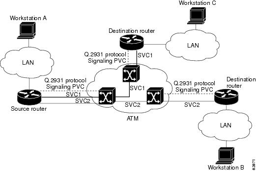
ATM uses out-of-band signaling. There is one dedicated PVC between the router and the ATM switch, over which all SVC call establishment and call termination requests flow. After a call is established, data transfer occurs over the SVC, from router to router. The signaling that accomplishes the call setup and teardown is called Layer 3 signaling or the Q.2931 protocol.
For out-of-band signaling, a signaling PVC must be configured before any SVCs can be set up. Figure 1 shows how a signaling PVC from the source router to the ATM switch is used to set up two SVCs. This is a fully meshed network; workstations A, B, and C can all communicate with each other.
Figure 1 SVCs within a signaling PVC
To configure the signaling PVC for all SVC connections, use the following command in interface configuration mode:
Router(config-if)# pvc [name] vpi/vci qsaal
Example:Router(config-if)# pvc cisco 0/5 qsaal
Configures the signaling PVC for an ATM main interface that uses SVCs.
Note
The VPI and VCI values must be configured consistently with the local switch. The standard values for VPI and VCI are 0 and 5, respectively.
Configuring the NSAP Address
Every ATM interface involved with signaling must be configured with a network service access point (NSAP) address. The NSAP address is the ATM address of the interface and must be unique across the network.
To configure an NSAP address, complete the tasks described in one of the following sections:
Configuring the ESI and Selector Fields
If the switch is capable of delivering the NSAP address prefix to the router by using ILMI, and the router is configured with a PVC for communication with the switch via ILMI, you can configure the end station ID (ESI) and selector fields by using the atm esi-address command. The atm esi-address command allows you to configure the ATM address by entering the ESI (12 hexadecimal characters) and the selector byte (2 hexadecimal characters). The NSAP prefix (26 hexadecimal characters) is provided by the ATM switch.
To configure the router to obtain the NSAP prefix from the switch and use locally entered values for the remaining fields of the address, use the following commands, beginning in interface configuration mode:
SUMMARY STEPS
1.
2.
3.
DETAILED STEPS
The atm nsap-address and atm esi-address commands are mutually exclusive. Configuring the router with the atm nsap-address command negates the atm esi-address setting, and configuring the router with the atm esi-address command negates the atm nsap-address setting. For information about using the atm esi-address command, see the section "Configuring the ESI and Selector Fields"
Creating an SVC
To create an SVC, use the following commands beginning in interface configuration mode:
SUMMARY STEPS
1.
2.
3.
DETAILED STEPS
Once you specify a name for an SVC, you can reenter interface-ATM-VC configuration mode by entering the svc name command. You can remove an SVC configuration by entering the no svc name command.
For a list of AAL types and encapsulations, see the section "Configuring the AAL and Encapsulation Type".
Customizing the ATM T3/E3 Network Module
You can customize the ATM T3/E3 network module. The features you can customize have default values that will probably suit your environment and do not need to be changed. However, you might need to enter configuration commands, depending on the requirements for your system configuration and the protocols you plan to route on the interface. Perform the tasks in the following sections if you need to customize the ATM T3/E3 network module:
Configuring ATM Framing
The ATM T3/E3 network module supports different framing types when it is configured as a T3 connection or an E3 connection. To configure T3 ATM framing on the T3/E3 network module enter the following command in interface configuration mode. The no form of this command removes T3 ATM framing.
To configure E3 ATM framing on the ATM T3/E3 network module, use the following command in interface configuration mode. The no form of this command removes E3 ATM framing.
Note
Setting the Loopback Mode
To loop all packets back to your ATM interface instead of to the network, use the following command in interface configuration mode:
To loop the incoming network packets back to the ATM network, use the following command in interface configuration mode:
Configuration Example
This section gives a basic example of how to configure the MN-1A-T3/E3 network module.
Router# configure terminalRouter(config)# interface ATM2/0Router(config-if)# ip address 10.0.0.2 255.0.0.0Router(config-if)# no atm ilmi-keepaliveRouter(config-if)# pvc 0/32Router(config-if-atm-vc)# cbr 34000Recommendations for Watermark Settings
Table 1 provides recommendations for watermark settings on the ATM T3/E3 module with a single VC.
For information about the traffic pattern used to test the watermark settings recommendations, see Traffic Pattern.
For an example of the router configuration, see Example of the Router Configuration Used for Watermark Testing.
Traffic Pattern
•
packet length - 300 bytes and 1400 bytes:–
350 for 1 Mbps; 700 for 2 Mbps; 1750 for 5 Mbps; and 3500 for 10 Mbps–
150 for 1 Mbps; 300 for 2 Mbps; 750 for 5 Mbps; and 1500 for 10 Mbps•
•
•
•
Example of the Router Configuration Used for Watermark Testing
The following example provides the router configuration that was used for the watermark testing.
Additional References
The following sections provide references related to the ATM T3/E3 network module.
Related Documents
Standards
No new or modified standards are supported by this feature, and support for existing standards have not been modified by this feature.
—
MIBs
RFCs
No new or modified RFCs are supported by this feature, and support for existing RFCs have not been modified by this feature.
—
Technical Assistance
Command Reference
This section documents only commands that are new or modified.
debug atm t3e3
To display debug messages for ATM T3/E3 network modules, use the debug atm t3e3 command in privileged EXEC mode. To disable debugging output, use the no form of this command.
debug atm t3e3 {data | flow | pa | sar | trace}
no debug atm t3e3 {data | flow | pa | sar | trace}
Syntax Description
Command Modes
Privileged EXEC (#)
Command History
Usage Guidelines
debug atm t3e3 data command
Use the debug atm t3e3 data command to display the incoming packet indications. Each incoming packet transferred by direct memory access (DMA) to the host memory by the SAR will cause a packet indication.
debug atm t3e3 flow command
Use the debug atm t3e3 flow command to display flow control indications.
When traffic sent to the SAR exceeds the peak cell rate for a particular virtual circuit (VC), the SAR indicates this to the host by sending flow control indications. These indications inform the host that either the high watermark or the low watermark has been reached for that VC queue.
When a high watermark is received from the SAR, indicating that the VC queue is full, the host will stop sending packets to the SAR until a low watermark indication is received. A low watermark indicates that the VC queue has been drained sufficiently to receive additional packets.
debug atm t3e3 pa command
Use the debug atm t3e3 pa command on those platforms supporting OIR to display the indications generated when the port adapter (the ATM T3/E3 network module) is subjected to OIR. This command is used principally during the port adapter initialization phase.
debug atm t3e3 sar command
Use the debug atm t3e3 sar command to display blocking commands or indications sent to or received from the SAR. This includes commands or indications of the creation or deletion of virtual circuits or virtual paths.
debug atm t3e3 trace command
Use the debug atm t3e3 trace command to display the hexadecimal representation of commands sent to or received from the SAR. To facilitate debugging, use this command in conjunction with the debug atm t3e3 sar command.
Examples
Example for the debug atm t3e3 data command
The following is sample output from the debug atm t3e3 data command:
Router# debug atm t3e3 dataDATA debugging is onRouter#*Jun 27 22:03:17.996: Packet Indication:*Jun 27 22:03:17.996: word 0: 0x00007D24*Jun 27 22:03:17.996: word 1: 0x00002F02*Jun 27 22:03:17.996: word 2: 0xEE323464*Jun 27 22:03:17.996: word 3: 0x006C006DTable 3 describes the significant fields shown in the display.
Example for the debug atm t3e3 flow command
The following example illustrates the output from the debug atm t3e3 flow command:
Router# debug atm t3e3 flowFLOW CNTL INDICATION debugging is onRouter#*Jun 27 15:14:13.123: Flow Indication:*Jun 27 15:14:13.123: word 0: 0x00000001*Jun 27 15:14:13.123: word 1: 0x300012C0*Jun 27 15:14:13.123: word 2: 0x18001060*Jun 27 15:14:13.123: word 3: 0x00080021*Jun 27 15:14:13.456: Flow Indication:*Jun 27 15:14:13.456: word 0: 0x00000001*Jun 27 15:14:13.456: word 1: 0x300012C0*Jun 27 15:14:13.456: word 2: 0x18001060*Jun 27 15:14:13.456: word 3: 0x00090022Table 4 describes the significant fields shown in the display.
Examples for the debug atm t3e3 pa command
The following examples illustrate the output from the debug atm t3e3 pa command.
The first example gives the output when the network module is removed:
Router# debug atm t3e3 paPA debugging is on*Jun 27 22:40:56.110: %OIR-6-REMCARD: Card removed from slot 2, interfaces disabled*Jun 27 22:40:56.122: *** Freed 6146 buffersThe second example gives the output when the network module is inserted, and gives the values of internal registers of the module:
*Jun 27 22:41:08.654: %OIR-6-INSCARD: Card inserted in slot 2, interfaces administratively
shut down
*Jun 27 22:41:11.402: sar_base_addr 0x5C800000*Jun 27 22:41:11.402: PCI_MEMBAR2_REG after configuring:0x5E000008*Jun 27 22:41:11.402: PCI_MEMBAR3_REG after configuring:0x5F000000*Jun 27 22:41:11.402: PCI_COMMAND_REG: Offset= 0x4; value= 0x2A00006*Jun 27 22:41:11.402: FPGA Base address is 0x5C900000*Jun 27 22:41:11.402: FPGA PCI config Reg is 0x02200002Examples for the debug atm t3e3 sar command
The following examples illustrate the output from the debug atm t3e3 sar command.
The first example displays command indications for setting up a VC and opening the reassembly channel and the segmentation channel in the SAR:
Router# debug atm t3e3 sarSAR debugging is onRouter# configure terminalRouter(config)# interface atm 2/0Router(config-if)# pvc 2/2Router(config-if-atm-vc)# exitRouter(config-if)#*Jun 27 22:12:28.816: ATM2/0: Setup_VC: vc:3 vpi:2 vci:2*Jun 27 22:12:28.816: ATM2/0: Open_Channel(RSY): CH (1), VPI (2), VCI (2)*Jun 27 22:12:28.816: ATM2/0: HI/LO watermarks: 526/263; PeakRate: 149760*Jun 27 22:12:28.816: ATM2/0: Open_Channel(SEG): CH (1), VPI (2), VCI (2)*Jun 27 22:12:28.820: ATM2/0: Setup_Cos: vc:3 wred_name:- max_q:0The second example displays the commands sent to the SAR and the acknowledgements returned when the VC is deleted and the segmentation and reassembly channels are closed:
Router(config-if)# no pvc 2/2Router(config-if)#*Jun 27 22:12:59.016: ATM2/0: Sent pending EOP successfully*Jun 27 22:12:59.016: ATM2/0: Close_Channel(RSY): Chan_ID (0x104)*Jun 27 22:12:59.016: ATM2/0: Close_Channel(RSY): Chan_ID (0x104) CLOSE*Jun 27 22:12:59.016: ATM2/0: Close_Channel: CLOSE_PENDING*Jun 27 22:12:59.016: ATM2/0: Close_Channel(SEG): Chan_ID (0x105)*Jun 27 22:12:59.016: ATM2/0: Close_Channel: CLOSEExamples for the debug atm t3e3 trace command
The first example illustrates the output from the debug atm t3e3 trace command when it is run without the debug atm t3e3 sar command being activated:
Router# debug atm t3e3 traceSAR CMD/ACK debugging is onRouter# configure terminalRouter(config)# interface atm 2/0router(config-if)# pvc 2/2Router(config-if-atm-vc)# exitRouter(config-if)#*Jun 27 22:15:09.284: Command Sent:*Jun 27 22:15:09.284: word 0: 0x00000480*Jun 27 22:15:09.284: word 1: 0x00012010*Jun 27 22:15:09.284: word 2: 0x00000000*Jun 27 22:15:09.284: word 3: 0x00000000*Jun 27 22:15:09.284: word 4: 0x00200020*Jun 27 22:15:09.284: word 5: 0x00000000*Jun 27 22:15:09.284: word 6: 0x00000000*Jun 27 22:15:09.284: word 7: 0x00000000*Jun 27 22:15:09.284: word 8: 0x00000000*Jun 27 22:15:09.284: Command Indication:*Jun 27 22:15:09.284: word 0: 0x00000000*Jun 27 22:15:09.284: word 1: 0x01042110*Jun 27 22:15:09.284: word 2: 0x01050000*Jun 27 22:15:09.284: word 3: 0x0000003B*Jun 27 22:15:09.284: ACK received = 200 usecs*Jun 27 22:15:09.284: Command Sent:*Jun 27 22:15:09.284: word 0: 0x01050480*Jun 27 22:15:09.284: word 1: 0x00011010*Jun 27 22:15:09.284: word 2: 0x02000000*Jun 27 22:15:09.284: word 3: 0x00010003*Jun 27 22:15:09.284: word 4: 0x00200020*Jun 27 22:15:09.284: word 5: 0x64B30000*Jun 27 22:15:09.284: word 6: 0x10C00000*Jun 27 22:15:09.284: word 7: 0x86850000*Jun 27 22:15:09.284: word 8: 0x00010040*Jun 27 22:15:09.284: word 9: 0x00000000*Jun 27 22:15:09.284: Command Indication:*Jun 27 22:15:09.284: word 0: 0x00010000*Jun 27 22:15:09.284: word 1: 0x00011110*Jun 27 22:15:09.284: word 2: 0x02000000*Jun 27 22:15:09.284: word 3: 0x0001003D*Jun 27 22:15:09.284: ACK received = 200 usecsTable 5 describes the significant fields shown in the display.
The second example illustrates the output from the debug atm t3e3 trace command run in conjunction with the debug atm t3e3 sar command.
In this example, each command sent to the SAR is displayed by the debug atm t3e3 sar command. Then the hexadecimal representation of the command and its acknowledgement are displayed by the debug atm t3e3 trace command.
Router# debug atm t3e3 traceSAR CMD/ACK debugging is onRouter# debug atm t3e3 sarSAR debugging is onRouter# configure terminalRouter(config)# interface atm 2/0router(config-if)# pvc 2/2Router(config-if-atm-vc)# exitRouter(config-if)#*Jun 27 22:15:09.284: ATM2/0: Setup_VC: vc:4 vpi:2 vci:2*Jun 27 22:15:09.284: ATM2/0: Open_Channel(RSY): CH (1), VPI (2), VCI (2)*Jun 27 22:15:09.284: Command Sent:*Jun 27 22:15:09.284: word 0: 0x00000480*Jun 27 22:15:09.284: word 1: 0x00012010*Jun 27 22:15:09.284: word 2: 0x00000000*Jun 27 22:15:09.284: word 3: 0x00000000*Jun 27 22:15:09.284: word 4: 0x00200020*Jun 27 22:15:09.284: word 5: 0x00000000*Jun 27 22:15:09.284: word 6: 0x00000000*Jun 27 22:15:09.284: word 7: 0x00000000*Jun 27 22:15:09.284: word 8: 0x00000000*Jun 27 22:15:09.284: Command Indication:*Jun 27 22:15:09.284: word 0: 0x00000000*Jun 27 22:15:09.284: word 1: 0x01042110*Jun 27 22:15:09.284: word 2: 0x01050000*Jun 27 22:15:09.284: word 3: 0x0000003B*Jun 27 22:15:09.284: ACK received = 200 usecs*Jun 27 22:15:09.284: ATM2/0: HI/LO watermarks: 526/263; PeakRate: 149760*Jun 27 22:15:09.284: ATM2/0: Open_Channel(SEG): CH (1), VPI (2), VCI (2)*Jun 27 22:15:09.284: Command Sent:*Jun 27 22:15:09.284: word 0: 0x01050480*Jun 27 22:15:09.284: word 1: 0x00011010*Jun 27 22:15:09.284: word 2: 0x02000000*Jun 27 22:15:09.284: word 3: 0x00010003*Jun 27 22:15:09.284: word 4: 0x00200020*Jun 27 22:15:09.284: word 5: 0x64B30000*Jun 27 22:15:09.284: word 6: 0x10C00000*Jun 27 22:15:09.284: word 7: 0x86850000*Jun 27 22:15:09.284: word 8: 0x00010040*Jun 27 22:15:09.284: word 9: 0x00000000*Jun 27 22:15:09.284: Command Indication:*Jun 27 22:15:09.284: word 0: 0x00010000*Jun 27 22:15:09.284: word 1: 0x00011110*Jun 27 22:15:09.284: word 2: 0x02000000*Jun 27 22:15:09.284: word 3: 0x0001003D*Jun 27 22:15:09.284: ACK received = 200 usecs*Jun 27 22:15:09.284: ATM2/0: Setup_Cos: vc:4 wred_name:- max_q:0
Feature Information for the Cisco ATM T3/E3 Network Module
Table 6 lists the release history for this feature.
Not all commands may be available in your Cisco IOS software release. For release information about a specific command, see the command reference documentation.
Use Cisco Feature Navigator to find information about platform support and software image support. Cisco Feature Navigator enables you to determine which Cisco IOS and Catalyst OS software images support a specific software release, feature set, or platform. To access Cisco Feature Navigator, go to http://www.cisco.com/go/cfn. An account on Cisco.com is not required.
Note