Feedback Feedback
|
Table Of Contents
Enhanced MF for FGD and Analog CAMA Trunks
Prerequisites for Enhanced MF for FGD and Analog CAMA Trunks
Restrictions for Enhanced MF for FGD and Analog CAMA Trunks
Information About Enhanced MF for FGD and Analog CAMA Trunks
How to Configure Enhanced MF for FGD and Analog CAMA Trunks
Enabling FGD EMF on Cisco 5x00 Platforms
Verifying and Troubleshooting FGD EMF
Enabling Analog CAMA on Cisco 2x00, and Cisco 3x00 ISRs
Verifying and Troubleshooting Analog CAMA
Enabling Info Digits for FGD EMF
Verifying and Troubleshooting Info Digits for FGD EMF
Verifying and Troubleshooting ESCO Code
Enabling e911 Support on SIP and VoIP Dial Peers
Verifying and Troubleshooting e911 Support on SIP and VoIP Dial Peers
Configuration Examples for Enhanced MF for FGD and Analog CAMA Trunks
FGD EMF on Cisco 5x00 Platforms: Example
Analog CAMA on Cisco 2x00 Platforms: Example
Info Digits for FGD EMF and Analog CAMA EMF: Example
E911 Support on SIP and VoIP Dial Peers: Example
Feature Information for Enhanced MF for FGD and Analog CAMA Trunks
Enhanced MF for FGD and Analog CAMA Trunks
First Published: June 19, 2006 OL-8775-01
Last Updated: May 21, 2010The Enhanced MF for FGD and Analog CAMA Trunks feature enhances the 911 interconnect capabilities of Cisco IOS based gateways. This document describes new E911 support requirements, which includes support for Enhanced Multi-frequency (MF) signaling for Feature Group D (FGD) and Analog Centralized Automated Message Accounting (CAMA) signaling protocols per National Emergency Number Association standards. This feature supports 20-digit ANI requirements and mapping of remote party IDs (RPID) to PANI.
Finding Feature Information in This Module
Your Cisco IOS software release may not support all of the features documented in this module. To reach links to specific feature documentation in this module and to see a list of the releases in which each feature is supported, use the "Feature Information for Enhanced MF for FGD and Analog CAMA Trunks" section.
Finding Support Information for Platforms and Cisco IOS Software Images
Use Cisco Feature Navigator to find information about platform support and Cisco IOS software image support. Access Cisco Feature Navigator at http://www.cisco.com/go/fn. You must have an account on Cisco.com. If you do not have an account or have forgotten your username or password, click Cancel at the login dialog box and follow the instructions that appear.
Contents
•
Prerequisites for Enhanced MF for FGD and Analog CAMA Trunks
•
•
•
•
Prerequisites for Enhanced MF for FGD and Analog CAMA Trunks
The following required hardware, software, and related protocols support the 20-digit ANI requirement and mapping of the remote party ID (RPID) to PANI:
•
•
•
•
•
Restrictions for Enhanced MF for FGD and Analog CAMA Trunks
•
•
•
•
•
•
•
•
Information About Enhanced MF for FGD and Analog CAMA Trunks
The Enhanced MF for FGD and Analog CAMA Trunks feature enhances 911 interconnect capabilities of Cisco IOS based gateways by sending two 10-digit ANIs to an SR using Feature Group D - Operator Services (FGD-OS) and CAMA trunks.
This feature meets FCC requirements for the following:
•
•
The following additional features are supported:
•
•
•
•
•
•
•
•
FCC E911 VoIP
As part of the FCC E911 VoIP order that was released in June, 2005, the FCC mandated that providers of interconnected VoIP services must provide E911 service to all of their customers as a standard feature, rather than as an optional enhancement. It was further required that E911 service be provided from wherever the customer is using the service, whether at home or elsewhere.
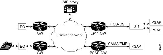
As a result, an advanced E911 solution has been created that includes a method to determine a user's location without assistance from the user. This location information (ALI) is provided along with the identification information (ANI) to the SR or PSAP, where supported. Because part of the connectivity to the SR or PSAP involves FGD-OS and analog CAMA signaling, this signaling has been modified to support sending ALI (sometimes referred to as Pseudo ANI [PANI]) along with the ANI.
Figure 1 shows an E911 network using packet gateways.
Figure 1
E911 Network using Packet Gateways
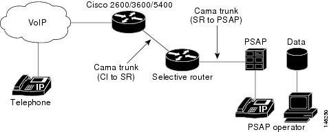
Figure 2 shows the SR interconnect topology (either CAMA or MF trunks can be used).
Figure 2 SR Interconnect Topology
20-Digit ANI
This feature adds 20-digit ANI support (ANI plus ALI) to the following signaling processes and platforms:
•
•
The following sections describe the requirements for 20-digit ANI support.
SIP INVITE to FGD MF/Analog CAMA Signal Conversion
The "FROM" field in SIP INVITE message contains the call back number (CBN) and this is mapped to ANI in FGD-EMF and Analog CAMA. The RPID contains the ESQK.
10- and 20-Digit Support for FGD MF Signaling (POI-T8 interfaces) on Cisco 5x00 Series Gateways
•
•
•
Enhanced MF Support for Analog CAMA on Cisco 3x00 Series Gateways (ISRs)
•
•
•
ANI II Digit Handling at Cisco 3x00 and Cisco 5x00 Gateways
•
–
–
–
ANI Failures for Analog CAMA Interfaces
The ANI/PANI failures adhere to NENA 03 002 Specifications and are described as follows:
•
•
–
–
–
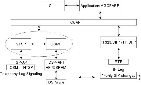
Figure 3 shows the voice software architecture, showing the interaction between various software modules for voice calls.
Figure 3 Software Architecture for Voice Applications
How to Configure Enhanced MF for FGD and Analog CAMA Trunks
TDM trunk configuration for 10-digit or 20-digit CAMA/MF signaling occurs at the trunk level. A gateway can be configured with some trunks supporting 10 digits and some supporting 20 digits. On existing trunks, you can enable this feature on a trunk by trunk basis. If you are setting up trunks for the first time, you must install a VoIP GW and bring trunks up to the SR as each trunk is deployed.
This section contains the following configuration tasks:
•
•
•
•
Enabling FGD EMF on Cisco 5x00 Platforms
The existing dsx1 subsystem in Cisco IOS software handles the configuration and management of the DS-0 timeslots and channels of DS1. It provides mechanisms for allocating timeslots to various signaling schemes and purposes. The ds0-group command in controller configuration mode is used to specify the channels and timeslots for the CAS group and CAS signaling type.
To support the new FGD variation, two new options have been added:
•
•
Prerequisites
Before configuring this feature, you must complete the following tasks:
•
–
•
–
•
SUMMARY STEPS
1.
2.
3.
4.
DETAILED STEPS
Examples
The following examples show the options that are available to configure 20-digit ANI (ANI + PANI)
Router(config-controller)# ds0-group 11 timeslots 11 type fgd-emf ?ani ANI addr info provisionedani-pani ANI and PANI addr info provisionedmf MF tone signalling<cr>Router(config-controller)# ds0-group 11 timeslots 11 type fgd-emf ani?ani ani-paniRouter(config-controller)# ds0-group 11 timeslots 11 type fgd-emf ani-pani ?<cr>Router(config-controller)# ds0-group 11 timeslots 11 type fgd-emf mf ?ani ANI addr info provisionedani-pani ANI and PANI addr info provisioned<cr>Router(config-controller)# ds0-group 11 timeslots 11 type fgd-emf mf aniRouter(config-controller)# ds0-group 11 timeslots 11 type fgd-emf mf ani-paniVerifying and Troubleshooting FGD EMF
To verify your configuration, use the show running-config command in global configuration mode.
To troubleshoot your configuration, use the debug ccsip messages command in global configuration mode.
Enabling Analog CAMA on Cisco 2x00, and Cisco 3x00 ISRs
To configure analog CAMA on Cisco 2x00, and Cisco 3x00 ISRs, use the following steps.
SUMMARY STEPS
1.
2.
3.
4.
DETAILED STEPS
Examples
The following example shows the options that are available to configure analog CAMA:
Router(config)# voice-port 1/0/1Router(config-voiceport)# signal cama ?KP-0-NPA-NXX-XXXX-ST Type 2 CAMA SignalingKP-0-NXX-XXXX-ST Type 1 CAMA SignalingKP-2-ST Type 3 CAMA SignalingKP-NPD-NXX-XXXX-ST Type 4 CAMA SignalingKP-0-NPA-NXX-XXXX-ST-KP-YYY-YYY-YYYY-ST CAMA Signaling with ANI/Pseudo ANI<cr>Verifying and Troubleshooting Analog CAMA
To verify your configuration, use the show running-config command in global configuration mode.
To troubleshoot your configuration, use the debug ccsip messages command in global configuration mode.
Enabling Info Digits for FGD EMF
To configure info digits for FGD EMF on the Cisco AS5x00 voice port, use the following steps. This function is enabled on the FXO interface.
For FGD EMF, the info digits can also be configured under the dial peer.
Restrictions
The following restrictions apply to enabling info digits for GFD EMF:
•
•
SUMMARY STEPS
1.
2.
3.
4.
DETAILED STEPS
Verifying and Troubleshooting Info Digits for FGD EMF
To verify your configuration, use the show running-config command in global configuration mode.
To troubleshoot your configuration, use the debug ccsip messages command in global configuration mode.
Configuring ESCO Code
To configure Emergency Services Central Office (ESCO) code, use the following steps.
SUMMARY STEPS
1.
2.
3.
4.
DETAILED STEPS
Examples
The following example shows options that are available to configure ESCO code:
Router(config)# voice-port 1/0/Router(config-voiceport)# ?Voice-port configuration commands:esco-code ESCO CodeRouter(config-voiceport)# esco-code ?WORD Three to four digit ESCO codeRouter(config-voiceport)# esco-code 111 ?<cr>Verifying and Troubleshooting ESCO Code
To verify your configuration, use the show running-config command in global configuration mode.
To troubleshoot your configuration, use the debug ccsip messages command in global configuration mode.
Enabling e911 Support on SIP and VoIP Dial Peers
In this feature, the user portion of the "FROM" header in the SIP Invite message is mapped to ANI (CBN), and the user portion of the "RPID" header is mapped to pANI. Previously, the behavior was to use RPID as ANI and to use the FROM header in ANI only if the RPID is not present. With this feature, the RPID field is mapped to the p-ANI field and this field is then passed to the VTSP/ Distributed Stream Media Processor (DSMP) layers for mapping into the pANI. To maintain backwards compatibility, this new functionality is enabled with the voice service voip sip e911 or voice-class sip e911 commands. In order for the new CLI to be checked, the following conditions must be true:
•
•
•
When the above is true, the SIP SPI will check if this gateway is configured for e911 support. The global and VoIP dial peer level CLI indicates whether e911 is configured. The global configuration is only checked when no dial peer is matched or if the dial peer setting is sipE911System. The dial peer value can have one of 3 values. They are as follows:
•
•
•
By default, the dial peer setting is set to sipE911System, which means that the global setting will be checked. If no VoIP dial peer is matched, the global CLI will be checked. The global setting will be either true or false where true indicates that e911 is enabled and false indicates that e911 is not enabled. A new boolean (globalE911Config) has been added to the voServiceSipCfg global structure. By default it is set to false, indicating that e911 is not enabled.
After the SIP SPI determines that e911 is enabled (dialpeer or global configuration mode), it will populate the pseudoANI field in ccCallInfo with the user portion of the RPID header and populate callingNumber in ccCallInfo with the user portion of the FROM header. If e911 is not enabled, the current configuration is used.
E911 is enabled with the e911 or voice-class sip e911 commands. To configure E911 on SIP for PANI using global or VoIP dialpeer configuration modes, use the following steps.
SUMMARY STEPS
1.
2.
3.
or
4.
DETAILED STEPS
Examples
The following example enables e911 services on a VoIP dial peer:
Router(config-dial-peer)# voice-class sip e911
The following example enables e911 services in global configuration mode under the voice service VoIP SIP configuration mode:
Router(config-term)# voice service voipRouter(conf-voi-serv)# sipRouter(conf-serv-sip)# e911Verifying and Troubleshooting e911 Support on SIP and VoIP Dial Peers
To verify your configuration, use the show running-config command in global configuration mode.
To troubleshoot your configuration, use the debug ccsip messages command in global configuration mode.
Configuration Examples for Enhanced MF for FGD and Analog CAMA Trunks
This sections contains configuration examples for the Enhanced MF for FGD and Analog CAMA Trunks feature.
•
•
•
•
FGD EMF on Cisco 5x00 Platforms: Example
The following examples configure 20-digit ANI (ANI + PANI)
Router(config-controller)# ds0-group 11 timeslots 11 type fgd-emf mf aniRouter(config-controller)# ds0-group 11 timeslots 11 type fgd-emf mf ani-paniAnalog CAMA on Cisco 2x00 Platforms: Example
The following example configures analog CAMA on a Cisco 2851:
Router(config-voiceport)# signal cama KP-0-NPA-NXX-XXXX-ST-KP-YYY-YYY-YYYY-STInfo Digits for FGD EMF and Analog CAMA EMF: Example
The following example configures info digits for FGD EMF on a Cisco AS5x00 voice port:
Router(voice-port)# info digits 91ESCO Code: Example
The following example configures ESCO code on a Cisco 2851:
Router(config)# voice-port 1/0/Router(config-voiceport)# esco-code 111E911 Support on SIP and VoIP Dial Peers: Example
The following example enables e911 services on a VoIP dial peer:
Router(config-dial-peer)# voice-class sip e911
The following example enables e911 services in global configuration mode under the voice service VoIP SIP configuration mode:
Router(config-term)# voice service voip sip e911Additional References
The Interconnect methodology from BellSouth Corporation is described at the following URL:
http://www.interconnection.bellsouth.com/guides/e911/html/gewcg001/c3_2.htm
Related Documents
Cisco IOS command references.
•
Cisco IOS Voice Configuration Library, including library preface and glossary, other feature documents, and troubleshooting documentation.
Cisco ISR 3303 Router information.
Cisco SIP protocol information.
Cross platform release notes information,
Describes the relationship between routers, gateways, Catalyst switches, and voice network modules and cards.
Standards
J-STD-034.7
Wireless Enhanced Emergency Services: TIA/EIA/IS-93 Modifications
NENA 03 002
NENA Recommendations for Enhanced MF signaling, E911 TANDEM to PSAP
MIBs
RFCs
Technical Assistance
Command Reference
This section documents new and modified commands only:
New Commands
•
Modified Commands
debug csm neat
To turn on debugging for all Call Switching Module (CSM) Voice over IP (VoIP) calls, use the debug csm neat command in privileged EXEC mode. To disable debugging output, use the no form of this command.
debug csm neat [slot | dspm | dsp | dsp-channel]
no debug csm neat [slot | dspm | dsp | dsp-channel]
Syntax Description
slot | dspm | dsp | dsp-channel
(Optional) Identifies the location of a particular digital signal processor (DSP) channel.
Command Modes
Privileged EXEC
Command History
Usage Guidelines
The debug csm neat command turns on debugging for all CSM VoIP calls. If no arguments are specified, debugging is enabled for all voice calls.
Note
The no debug cms neat command turns off debugging information for all voice calls.
If the slot, dspm, dsp, or dsp-channel arguments are specified (if the specified DSP channel is engaged in a CSM call), CSM call-related debugging information is turned on for this channel. The no form of this command turns off debugging for that particular channel.
Examples
The following examples show sample output from the debug csm neat command. The following shows that CSM has received an event from ISDN.
Router# debug csm neatMarch 18 04:05:07.052: EVENT_FROM_ISDN::dchan_idb=0x60D7B6B8, call_id=0xCF, ces=0x1bchan=0x0, event=0x1, cause=0x0Table 1 describes the significant fields shown in the display.
The following example shows that CSM has allocated the CSM voice control block for the DSP device on slot 1 port 10 for this call.
March 18 04:05:07.052: VDEV_ALLOCATE: slot 1 and port 10 is allocated.In this example, CSM must first allocate the CSM voice control block to initiate the state machine. After the voice control block has been allocated, CSM obtains from the DSP Resource Manager the actual DSP channel that will be used for the call. At that point, CSM will switch to the actual logical port number. The slot number in this example refers to the physical slot on the Cisco AS5400 access server. The port number is the logical DSP number interpreted as listed in Table 2.
The following example shows that the function csm_vtsp_init_tdm() has been called with a voice control block of address 0x60B8562C. This function will be called only when the call is treated as a voice call.
March 18 04:05:07.052: csm_vtsp_init_tdm (voice_vdev=0x60B8562C)The following example shows that CSM has obtained a DSP channel from the DSP Resource Manager:
March 18 04:05:07.052: csm_vtsp_init_tdm: dsprm_tdm_allocate: tdm slot 1, dspm 2, dsp 5,
dsp_channel 1csm_vtsp_init_tdm: dsprm_tdm_allocate: tdm stream 5, channel 9, bank 0,
bp_channel 10
Table 3 describes the significant fields shown in the DSP channel initialized TDM display.
The following shows that CSM received an incoming call event from ISDN:
March 18 04:05:07.052: EVENT_FROM_ISDN:(00CF): DEV_INCALL at slot 1 and port 20Slot 1, port 20 means the logical DSP channel 20 (mapped to DSPRM 2, DSP 5, DSP channel 1).
The following shows that the DEV_INCALL message been translated into a CSM_EVENT_ISDN_CALL message:
March 18 04:05:07.052: CSM_PROC_IDLE: CSM_EVENT_ISDN_CALL at slot 1, port 20This message is passed to the CSM central state machine while it is in the CSM_IDLE state and is in the CSM_PROC_IDLE procedure. The logical DSP channel port 20 on slot 1 is used to handle this call.
The following shows that CSM has invoked the vtsp_ic_notify() function with a CSM voice call control block 0x60B8562C.
March 18 04:05:07.052: vtsp_ic_notify : (voice_vdev= 0x60B8562C)Inside this function, CSM will send a SETUP INDICATION message to the VTSP. This function will be invoked only if the call is a voice call.
The following shows that CSM received a SETUP INDICATION RESPONSE message from the VTSP as an acknowledgment.
March 18 04:05:07.056: csm_vtsp_call_setup_resp (vdev_info=0x60B8562C,
vtsp_cdb=0x60FCA114)
This means that the VTSP received the CALL SETUP INDICATION message previously sent and has proceeded to process the call.
•
•
The following shows that CSM received a CALL CONNECT message from the VTSP:
March 18 04:05:07.596: csm_vtsp_call_connect (vtsp_cdb=0x60FCA114, voice_vdev=0x60B8562C)This indicates that the VTSP received a CONNECT message for the call leg initiated to the Internet side.
•
•
The following shows that while CSM is in the CSM_IC2_RING state, it receives a SETUP INDICATION RESPONSE from the VTSP. This message is translated into CSM_EVENT_MODEM_OFFHOOK and passed to the CSM central state machine.
March 18 04:05:07.596: CSM_PROC_IC2_RING: CSM_EVENT_MODEM_OFFHOOK at slot 1, port 20The following shows that CSM received a CONNECT message from ISDN for the call using the logical DSP channel on slot 1 and port 20:
March 18 04:05:07.616: EVENT_FROM_ISDN:(00CF): DEV_CONNECTED at slot 1 and port 20The following shows that CSM translated the CONNECT event from ISDN into the CSM_EVENT_ISDN_CONNECTED message, which is then passed to the CSM central state machine:
March 18 04:05:07.616: CSM_PROC_IC4_WAIT_FOR_CARRIER: CSM_EVENT_ISDN_CONNECTED at slot 1,
port 20
The following shows that CSM received a CALL SETUP REQUEST from the VTSP:
May 16 12:22:27.580: csm_vtsp_call_setup_request (vtsp_cdb=0x60FCFA20,
vtsp_sdb=0x60DFB608)
This represents a request to make an outgoing call to the PSTN.
•
•
The following shows that the physical DSP channel has been allocated for this outgoing call:
May 16 12:22:27.580: csm_vtsp_call_setup_request: tdm slot 1, dspm 5, dsp 4, dsp_channel 1The following shows the on-chip and backplane TDM channel assigned to this DSP channel:
May 16 12:22:27.580: csm_vtsp_call_setup_request: tdm stream 5, channel 25, bank 0,
bp_channel 27
In this sample output, tdm stream 5, channel 25, bank 0, bp_channel 27 indicates the on-chip and backplane TDM channel assigned to this DSP channel. Stream 5, channel 25 gives the on-chip TDM channel mapped to the DSP; bank 0, bp_channel 27 means that the backplane stream 0 and backplane channel 1 are assigned to this DSP.
The following shows the calling number and the called number for this call.
May 16 12:22:27.580: csm_vtsp_call_setup_request: calling number: 10001, called number:
30001
The following shows that the CALL SETUP REQUEST from the VTSP has been translated into the ' CSM_EVENT_MODEM_OFFHOOK message and is passed to the CSM central state machine:
May 16 12:22:27.580: CSM_PROC_IDLE: CSM_EVENT_MODEM_OFFHOOK at slot 1, port 54The logical DSP channel number for the DSP (slot 1, port 54) is now displayed, which maps to the physical DSP channel slot 1, dspm 5, dsp 4, dsp_channel 1.
The following shows that CSM collected all the digits for dialing out:
May 16 12:22:27.580: CSM_PROC_OC3_COLLECT_ALL_DIGIT: CSM_EVENT_GET_ALL_DIGITS at slot 1,
port 54
For PRI and for applications that do not require digit collection of outdialing digits (for example, voice calls), the intermediate digit collection states are omitted and the CSM state machine moves to this state directly, pretending that the digit collection has been done.
The following shows an information message:
March 16 12:22:27.580: CSM_PROC_OC3_COLLECT_ALL_DIGIT: called party num: (30001) at slot
1, port 54
The following shows that CSM attempts to find a free signalling D channel to direct the outgoing call:
March 16 12:22:27.580: csm_vtsp_check_dchan (voice_vdev=0x60B8562C)March 16 12:22:27.580: csm_vtsp_check_dchan (vtsp requested dchan=0x60D7ACB0, dchan_idb=0x60E8ACF0)March 16 12:22:27.580: csm_vtsp_check_dchan (voice_vdev=0x60B8562C)March 16 12:22:27.580: csm_vtsp_check_dchan (vtsp requested dchan=0x60D7ACB0, dchan_idb=0x60D7ACB0)In the case of voice calls, the free signaling D channel must match the voice interface specified inside the signalling data block (vtsp_sdb) passed from the VTSP.
The following shows that CSM has received an event from ISDN:
March 16 12:22:27.624: EVENT_FROM_ISDN::dchan_idb=0x60D7ACB0, call_id=0xA121, ces=0x1
bchan=0x1E, event=0x3, cause=0x0
In this sample output:
•
•
•
•
The following shows that CSM has received a CALL PROCEEDING message from ISDN.
March 16 12:22:27.624: EVENT_FROM_ISDN:(A121): DEV_CALL_PROC at slot 1 and port 54The following shows that the CALL PROCEEDING event received from ISDN has been interpreted as a CSM_EVENT_ISDN_BCHAN_ASSIGNED message:
*March 16 12:22:27.624: CSM_PROC_OC4_DIALING: CSM_EVENT_ISDN_BCHAN_ASSIGNED at slot 1,
port 54
ISDN has assigned a B channel for this outgoing call. This B channel must be on the same PRI span as the signalling D channel allocated previously.
The following shows that the csm_vtsp_setup_for_oc function is called:
March 16 12:22:27.624: csm_vtsp_setup_for_oc (voice_vdev=0x60B8562C)This is invoked when an outgoing call initiated by the VTSP receives a response from the ISDN stack.
The following shows that ISDN has sent a CONNECT message to CSM indicating that the call leg to the PSTN side has been established:
March 16 12:22:28.084: EVENT_FROM_ISDN::dchan_idb=0x60D7ACB0, call_id=0xA121, ces=0x1bchan=0x1E, event=0x4, cause=0x0March 16 12:22:28.084: EVENT_FROM_ISDN:(A121): DEV_CONNECTED at slot 1 and port 54The following shows that while CSM is in the OC5_WAIT_FOR_CARRIER state, it has received the 'CONNECT' message from ISDN and has translated it into the CSM_EVENT_ISDN_CONNECTED message, which is passed to the CSM central state machine:
March 16 12:22:28.084: CSM_PROC_OC5_WAIT_FOR_CARRIER: CSM_EVENT_ISDN_CONNECTED at slot 1,
port 54
The following shows that the function vtsp_confirm_oc() has been called:
March 16 12:22:28.084: vtsp_confirm_oc : (voice_vdev= 0x60B8562C)This is invoked after CSM received the CONNECT message from ISDN. CSM sends a confirmation of the CONNECT to the VTSP.
ds-0 group (T1)
To specify the DS0 time slots that make up a logical voice port on a T1 controller, to specify the signaling type by which the router communicates with the PBX or PSTN, and to define T1 channels for compressed voice calls and the channel-associated signaling (CAS) method by which the router connects to the PBX or PSTN, use the ds0-group command in controller configuration mode. To remove the group and signaling setting, use the no form of this command.
Cisco 2691, Cisco 2600XM Series, Cisco 2800 Series (Except Cisco 2801), Cisco 3660, Cisco 3700 Series, Cisco 3800 Series
ds0-group ds0-group-number timeslots timeslot-list type {e&m-delay-dial | e&m-fgd | e&m-immediate-start | e&m-lmr | e&m-wink-start | ext-sig | fgd-eana | fgd-emf [mf] [ani-pani] [ani] | fxo-ground-start | fxo-loop-start | fxs-ground-start | fxs-loop-start}
no ds0-group ds0-group-number
Cisco AS5300, Cisco AS5350, Cisco AS5400, and Cisco AS5850
ds0-group ds0-group-number timeslots timeslot-list [service service-type] [type [e&m-fgb [dtmf | mf] | e&m-fgd [dtmf | mf [dnis | ani-dnis [info-digits-no-strip] | fgd-emf [ani-pani] [ani] | service service-type] | e&m-immediate-start | fxs-ground-start | fxs-loop-start | fgd-eana [ani-dnis | mf] | fgd-os [dnis-ani | mf] | r1-itu [dnis] | sas-ground-start | sas-loop-start | none]]
no ds0-group ds0-group-number
Syntax Description
ds0-group-number
A value that identifies the DS0 group. Range is 0 to 23.
timeslots timeslot-list
Lists time slots in the DS0 group. The timeslot-list argument is a single time-slot number, a single range of numbers, or multiple ranges of numbers separated by commas. Range is 1 to 24. Examples are as follows:
•
•
•
•
•
Specifies the type of signaling for the DS0 group. The signaling method selection for the type keyword depends on the connection that you are making. The ear and mouth (E&M) interface allows connection for PBX trunk lines (tie lines) and telephone equipment. The Foreign Exchange Station (FXS) interface allows connection of basic telephone equipment and PBX. The Foreign Exchange Office (FXO) interface is for connecting the central office (CO) to a standard PBX interface where permitted by local regulations; it is often used for off-premise extensions (OPXs). Types are as follows:
•
•
•
•
•
•
•
•
•
•
•
•
•
•
•
service service-type
(Optional) Specifies the type of service.
•
•
•
•
•
dtmf
(Optional) Specifies dual tone multifrequency (DTMF) tone signaling.
mf
(Optional) Specifies multifrequency (MF) tone signaling
ani
(Optional) Provisions ANI address information.
ani-dnis
(Optional) Specifies automatic number identification (ANI) and dialed number identification service (DNIS) address information provisioning for FGD OS.
ani-pani
(Optional) Provisions ANI and PANI address information.
dnis-ani
(Optional) Specifies ANI and DNIS address information provisioning for FGD EANA.
dnis
(Optional) Specifies DNIS address information provisioning.
info-digits-no-strip
(Optional) Retains info digits on the Cisco AS5x00 platforms.
1 Used only with the type none keywords on the Cisco AS5x00 platforms.
Defaults
There is no DS0 group. Calls are allowed in both directions.
Command Modes
Controller configuration
Command History
Usage Guidelines
The ds0-group command automatically creates a logical voice port that is numbered as follows:
•
–
•
–
Although only one voice port is created for each group, applicable calls are routed to any channel in the group.
Be sure that you take the following into account when you are configuring DS0 groups:
•
•
•
Note
Examples
The following example enables FGD EMF:
controller T1 1/0ds0-group 11 timeslots 11 type fgd-emf anids0-group 11 timeslots 11 type fgd-emf ani-paniThe following example shows ranges of T1 controller time slots configured for FXS ground-start and FXO loop-start signaling:
controller T1 1/0framing esflinecode b8zsds0-group 1 timeslots 1-10 type fxs-ground-startds0-group 2 timeslots 11-24 type fxo-loop-startThe following example shows ranges of T1 controller time slots configured for FXS ground-start signaling:
controller T1 1/0ds0-group 1 timeslots 1-4 type fxs-ground-startThe following example illustrates setting the T1 channels for Signaling System 7 (SS7) service on any trunking gateway using the mgcp keyword:
ds0-group 0 timeslots 1-24 type none service mgcpIn the following example, the time slot maximum is 12 and the time slot is 1, so two voice-ports are created successfully.
controller T1 0/0ds0-group 0 timeslots 1-4 type e&m-immediate-startds0-group 1 timeslots 6-12 type e&m-immediate-startIf a third DS0 group is added, the voice port is rejected even though the total number of voice channels is less than 16.
ds0-group 2 timeslots 17-18 type e&m-immediate-startIn the following example, the signaling type is set to E&M LMR:
ds0-group 0 timeslots 1-10 type e&m-lmrYou have the option to retain info digits when you are configuring E&M Type II Feature Group D with MF signaling and ANI/DNIS for calls being sent over IP. Info digits denote the subscriber type, and the info-digits keyword prepends info digits to the calling number.
On inbound calls from a T1 FGD voice-port with MF ANI-DNIS, when ANI information is obtained, it is passed unaltered to the next matching dial peer, either POTS or VoIP. The addition of the info-digits-no-strip keyword allows you to retain the info digits portion of the ANI information; the modified ANI is then passed to the next matching dial peer. Normally, info digits are not valid for calls going over IP and are, therefore, stripped off. The ability to retain info digits is particularly useful for calls that are not leaving the PSTN network and are just being hairpinned back.
In the following example, the E&M Type II Feature Group D is configured with MF signaling and ANI/DNIS over IP while retaining info digits:
ds0-group 0 timeslots 1-24 type e&m-fgd mf ani-dnis info-digits-no-stripRelated Commands
e911
To enable E911 system services for SIP on the VoIP dial peer, use the e911 command in voice service VoIP configuration mode. To disable SIP E911 functionality, use the no form of this command.
e911
no e911
Syntax Description
This command has no arguments or keywords.
Command Default
Disabled
Command Modes
Voice service VoIP (dial peer) configuration mode.
Command History
Usage Guidelines
The no form of the command disables E911 functionality from a global perspective. Output from the show running-config command shows whether E911 is configured. See also the voice-class sip e911 and debug csm neat commands.
Examples
The following example enables E911 services in voice service VoIP SIP configuration mode:
Router# configure terminalRouter(config-term)# voice service voipRouter(conf-voi-serv)# sipRouter(conf-serv-sip)# e911The following example disables E911 functionality:
Router(conf-serv-sip)# no e911Related Commands
esco-code
To configure Emergency Services Central Office Code (ESCO) code, use the esco-code command in voice-port configuration mode. To disable ESCO code, use the no form of this command.
esco-code word
no esco-code
Syntax Description
Command Default
The default is 000.
Command Modes
Voice-port configuration
Command History
Examples
The following example configures ESCO services using a three-digit code on a Cisco 2851:
Router(config)# voice-port 1/0/1Router(config-voiceport)# esco-code 111Related Commands
Sets the dial peer configuration to sipE911System on a specific dial peer.
Enables sipE911System services for SIP voice service VoIP.
signal
To specify the type of signaling for a voice port, use the signal command in voice-port configuration mode. To reset to the default, use the no form of this command.
Foreign Exchange Office (FXO) and Foreign Exchange Station (FXS) Voice Ports
signal {loop-start | ground-start}
no signal {loop-start | ground-start}
Ear and mouth (E&M) Voice Ports
signal {wink-start | immediate | delay-dial | lmr}
no signal {wink-start | immediate | delay-dial | lmr}
Centralized Automatic Message Accounting (CAMA) Ports
signal {cama {kp-0-nxx-xxxx-st | kp-0-npa-nxx-xxxx-st | kp-2-st | kp-npd-nxx-xxxx-st | kp-0-npa-nxx-xxxx-st-kp-yyy-yyy-yyyy-st} | groundstart | loopstart}
no signal {cama {kp-0-nxx-xxxx-st | kp-0-npa-nxx-xxxx-st | kp-2-st | kp-npd-nxx-xxxx-st | kp-0-npa-nxx-xxxx-st-kp-yyy-yyy-yyyy-st} | groundstart | loopstart}
Syntax Description
Command Default
FXO and FXS interfaces: loop-start
E&M interfaces: wink-start
CAMA interfaces: loop-startCommand Modes
Voice-port configuration
Command History
Usage Guidelines
This command applies to analog voice ports only.
Using the signal command for an FXO or FXS voice port changes the signal value for both voice ports on a voice port module (VPM) card.
Note
Configuring this command for an E&M voice port changes only the signal value for the selected voice port. In either case, the voice port must be shut down and then activated before the configured values are affective.
Some PBXs miss initial digits if the E&M voice port is configured for immediate start signaling. Use immediate start signaling for dial pulse outpulsing only and only on circuits for which the far end is configured to accept digits within a few milliseconds of seizure. Delay dial signaling, which is intended for use on trunks and not lines, relies on the far end to return an off-hook indication on its M-lead as soon as the circuit is seized. When a receiver is attached, the far end removes the off-hook indication to indicate that it is ready to receive digits. Delay dial must be configured on both ends to work properly. Some devices have a limited number of DTMF receivers. This type of equipment must delay the calling side until a DTMF receiver is available.
To specify which VIC2-2FXO or VIC2-4FXO card ports are designated as dedicated CAMA ports for emergency 911 calls, use the signal cama command. No two service areas in the existing North American telephony infrastructure supporting E911 calls have identical service implementations, and many of the factors that drive the design of emergency call handling are matters of local policy and therefore outside the scope of this document. Local policy determines which ANI format is appropriate for the specified Physical Service Access Point (PSAP) location.
The following four types of ANI transmittal schemes are based on the actual number of digits transmitted toward the E911 tandem. In each instance, the actual calling number is preceded with a key pulse (KP) followed by an information (I) field or a NPD, which is then followed by the ANI calling number, and finally is followed by a start pulse (ST), STP, ST2P, or ST3P, depending on the trunk group type in the PSTN and the traffic mix carried.
The information field is one or two digits, depending on how the circuit was ordered originally. For one-digit information fields, a value of 0 indicates that the calling number is available. A value of 1 indicates that the calling number is not available. A value of 2 indicates an ANI failure. For a complete list of values for two-digit information fields, see SR-2275: Telcordia Notes on the Networks at www.telcordia.com.
•
The calling phone number is transmitted, and the NPA is implied by the trunk group and not transmitted.
•
The I field consists of single-digit NPD-to-NPA mapping. When the calling party number of 415-555-0122 places a 911 call, and the Cisco 2600 series or Cisco 3600 series has an NPD (0)-to-NPA (415) mapping, the NPA signaling format is received by the selective router at the central office (CO).
Note
•
The E.164 number is fully transmitted.
•
Twenty digits support (two 10 digit numbers) on FGD-OS in the following format, KP+II+10 digit ANI+ST+KP+7/10 digit PANI+ ST
•
kp-2-st transmission is used if the PBX is unable to out-pulse the ANI. If the ANI received by the Cisco router is not as per configured values, kp-2-st is transmitted. For example, if the voice port is configured for out-pulsing a ten-digit ANI and the 911 call it receives has a seven-digit calling party number, the router transmits kp-2-st.
Note
Examples
The following example configures ground-start signaling as the signaling type for a voice port, which means that both sides of a connection can place a call and hang up:
Router(config)# voice-port 1/1/1Router(config-voiceport)# signal ground-startThe following example configures a 10-digit ANI transmission:
Router(config)# voice-port 1/0/0Router(config-voiceport)# signal cama kp-0-npa-nxxx-xxxx-stThe following example configures 20-digit CAMA Signaling with ANI/Pseudo ANI:
Router(config-voiceport)# signal cama KP-0-NPA-NXX-XXXX-ST-KP-YYY-YYY-YYYY-STRelated Commands
voice-class sip e911
To enable SIP E911 system services on a dial peer, use the voice-class sip e911 command in VoIP dialpeer configuration mode. To disable SIP E911 services, use the no form of this command.
voice-class sip e911
no voice-class sip e911
Syntax Description
This command has no arguments or keywords.
Command Default
The dial peer uses the global setting.
Command Modes
VoIP dialpeer configuration mode.
Command History
Usage Guidelines
The no form of this command sets the dial peer configuration to disable, which indicates that E911 will not be used for this peer. Because the no version of the command causes non default behavior, it can been seen in the show running-config output. See also the e911 and debug csm neat commands.
Examples
The following examples enable and disable E911 services on a VoIP dial peer:
Router(config)# dial-peer voice 2
Router(config-dial-peer)# voice-class sip e911
*Jun 06 00:47:20.611: setting peer 2 to enableRouter(config-dial-peer)# no voice-class sip e911*Jun 06 00:49:58.931: setting peer 2 to disableRelated Commands
Glossary
ANI: Automatic number identification. SS7 (signaling system 7) feature in which a series of digits, either analog or digital, are included in the call, identifying the telephone number of the calling device. In other words, ANI identifies the number of the calling party.
CAMA: Centralized Automated Message Accounting
CSM: Call Service Module
DNIS: Dialed Number Identification Service. When a call arrives at an ACD or PBX, the carrier sends a digital code on the trunk line. The switch can read this code to determine how it should dispatch the call. Typically, this value is the specific number dialed by the user. By mapping each possible code with an internal extension, the switch can provide direct inward dialing (DID).
DSMP: Distributed Stream Media Processor
DSP: Digital Signal Processor
DTMF: dual tone multifrequency. Tones generated when a button is pressed on a telephone, primarily used in the U.S. and Canada.
E911: Enhanced 911
EMF: Enhanced MF signaling
ESCO: Emergency Services Central Office Code
ESQK: Emergency Services Query Key
ESRD: Emergency Services Routing Digits
ESRK: Emergency Services Routing Key
FGD-OS: Feature Group D - Operator Services
FXS: Foreign Exchange Station. An FXS interface connects directly to a standard telephone and supplies ring, voltage, and dial tone. Cisco's FXS interface is an RJ-11 connector that allows connections to basic telephone service equipment, keysets, and PBXs.
IDB: interface description block
ISR: Intermediate Session Routing. Initial routing algorithm used in APPN. ISR provides node-to-node connection-oriented routing. Network outages cause sessions to fail because ISR cannot provide nondisruptive rerouting around a failure. ISR was replaced by HPR.
KP: Key Pulse, an MF signaling tone (digit)
MF: Multi-frequency, a type of signaling used on analog interoffice and 911 trunks
NENA: National Emergency Number Association
PANI: Pseudo ANI (corresponds to location information)
PSAP: Public Safety Answering Point
RPID: Remote Party Identification
ST: Start, an MF signaling tone (digit)
STP: Start Prime, an MF signaling tone (digit)
VoIP: Voice over IP
VTSP: Voice Telephony Service Provider
Note
Feature Information for Enhanced MF for FGD and Analog CAMA Trunks
Table 4 lists the release history for this feature.
Not all commands may be available in your Cisco IOS software release. For release information about a specific command, see the command reference documentation.
Cisco IOS software images are specific to a Cisco IOS software release, a feature set, and a platform. Use Cisco Feature Navigator to find information about platform support and Cisco IOS software image support. Access Cisco Feature Navigator at http://www.cisco.com/go/fn. You must have an account on Cisco.com. If you do not have an account or have forgotten your username or password, click Cancel at the login dialog box and follow the instructions that appear.
Note
© 2006 Cisco Systems, Inc. All rights reserved.