Feedback
Table Of Contents
Configuring the Cisco ASN Gateway
Network Admission of an Authenticated User
Support of Un-Authenticated User
Configuring AAA for Accounting Types
IP Address Allocation Using DHCP
Configuring IP Address Allocation
Support of Multiple Hosts Behind a SS
Service Flow Creation and Management
Multiple Service Flow Creation
Configuring ASN Gateway Service
Mapping of Service Flows to DiffServ Classes
Configuring Service Flows on the ASN Gateway
Configuring Service Flow Packet Classification
Mobile Subscriber Station De-Registration
AAA Accounting Start-Stop-Interim
Unpredictive Controlled Handoff
Keepalive Support for R6 Interface
ASN Gateway Session Redundancy and High Availability Infrastructure
Configuring Session Redundancy
Load Balancing Configuration Task List
Configuring Cisco IOS SLB for Load Balancing
Configuring the ASN Gateway for Load Balancing
ASN Gateway Configuration Example
Configuring SNMP on the ASN Gateway
SNMP Configuration Examples on the ASN Gateway
Configuring the Cisco ASN Gateway
This feature module explains and discusses the feature set for the Cisco ASN Gateway. Additionally, this feature module explains how to configure those features, and provides sample configurations when appropriate.
This chapter contains information on the following features:
–
Network Admission of an Authenticated User
–
•
–
–
•
–
–
–
–
–
•
–
•
–
–
–
–
–
•
EAP Authentication
The Authenticator function is part of the ASN gateway. This function performs the role of an anchored authenticator for the specific subscriber for the duration of the session. During further mobility events (for example, as a subscriber moves between base stations served by the ASN gateway), the authenticator anchor remains stationary.
ASN Gateway Release 1.0 does not support inter-ASN gateway mobility. If a subscriber moves to a base station served by a new ASN gateway, the anchor authenticator is now hosted at the new ASN Gateway. A full re-authentication of the subscriber is required.
The Radius Client for Authentication and Accounting is collocated with the Authenticator function.
The supported Authentication types in Release 1.0 are EAP-TLS and unauthenticated users.
The ASN Gateway acts as an EAP relay and is agnostic to the EAP method. EAP transport is done between the ASN Gateway and the base station as a control exchange. The base station functions as an EAP-relay, converting from Pair-wise Master Key version 2 (PKMv2) to the EAP messages over to the ASN Gateway. The ASN Gateway is an EAP pass-through, and any key that generates EAP methods is supported in the system.
PKMv2 is used to perform over-the-air user authentication. PKMv2 transfers EAP over the IEEE 802.16 air interface between the MS and the base station. The base station relays the EAP messages to the Authenticator in the ASN Gateway. The AAA client on the Authenticator encapsulates the EAP message in AAA protocol packets, and forwards them through one (or more) AAA proxies to the AAA server in the CSN of the home NSP. In roaming scenarios, one (or more) AAA brokers with AAA proxies may exist between the Authenticator and the AAA server. All AAA sessions always exist between the Authenticator and AAA server, with optional AAA brokers providing a conduit for NAI realm-based routing.
Note
Subscriber Identities
The following three types of subscriber identities are used on the ASN Gateway:
MSID
The MSID is the 802.16 identifier used for all subscriber stations, and is used in all the messages over R6. This identifier associates all requests from a SS/MSS to the ASNGateway. Typically it is the MACID.
EAP Outer Identity
The EAP outer identifier format is pseudo-identity@domain. The domain portion is used to route to the correct home AAA server. The domain portion is also used to access the local configured group configuration on the ASN Gateway.
EAP Inner Identity
The EAP inner identifier is sent directly between the SS/MSS to the AAA server, and is provisioned at the SS/MSS.
Network Admission of an Authenticated User
The following series of events illustrates how the network admits an authenticated user.
1.
2.
3.
4.
5.
6.
7.
8.
9.
10.
11.
12.
13.
14.
Support of Un-Authenticated User
Support of un-authenticated users is required in the following scenarios, and can be used for pre-paid systems, or emergency calls.
•
•
•
Configuring Authentication
This section provides information on how to configure authentication and authorization on the Cisco ASN Gateway. To enable authenticated calls between the ASN Gateway and a subscriber, perform the following tasks on the ASN Gateway:
•
Configuring AAA for Accounting Types
To configure accounting types on the ASN Gateway, perform the following tasks:
Configuring Authorization
To configure authorization on the ASN Gateway, perform the following task:
Configuring Authentication
To configure authentication on the ASN Gateway, perform the following task:
RADIUS Server
To configure the RADIUS server host on the ASN Gateway, perform the following task:
Configuring User Groups
To configure a user group on the ASN Gateway, perform the following tasks:
Note
Verifying the Configuration
The authentication method of a subscriber displays whether the call was authenticated with EAP, or unauthenticated for the respective user group (any, unauthenticated, domain specific).
For an authenticated call, the Auth Policy and AK Context is also displayed.
To verify your authentication configuration, use the following commands:
Step 1
router# show wimax agw subscriber msid
Displays subscriber authentication information.
Configuration Examples
Here is sample output for subscriber information for an unauthenticated call:
Router>sh wimax agw subscriber msid 1000.0003.0000Connection time 000:01:05Auth policy 0X0(0)Number of TIDs 1TID Key 10.1.1.82/2.2.2.2/1000.0003.0000Peer TID 0X2(2)FT MS State Change(9), MT Attachment Request(8)Our TID 0x8001(32769)Subscriber address 2.2.0.9, type IPv4, organization IETFSubscriber address method Dynamic, source DHCP relaySubscriber address assigned on flow downlink ID 17Subscriber address prefix len allocated 32, aggregate 32Subscriber address traffic sent 0 packets, 0 bytesSubscriber address traffic received 0 packets, 0 bytesSubscriber address DHCP XID 2391, server 0.0.0.0, htype 1Subscriber address DHCP client ID 1000.0003.0000, length 6Subscriber address DHCP Refresh time 86400 secondsNumber of sessions 1Session details:FSM in state Ready(7) on last event Rx Attach Ack(14)Authentication method unauthenticatedAssociated user group **unauthenticated**Signalling address local 2.2.2.2, remote 10.1.1.82Signalling UDP port local 2231, remote 2231Idle for inbound 00:01:10, outbound 00:01:10Ingress Address filtering 0 packets, 0 bytesNumber of flows 1Flow details ISF(0)FSM in state SF Ready(4) on last event Up(1)Transaction ID used 0X8001(32769)Data ID local 0x9(9), remote 0x2(2)Data address local 2.2.2.2, remote 10.1.1.82Data traffic sent 2 packets, 656 bytesData traffic received 2 packets, 1208 bytesAccounting last record sent Interim(3)Idle for inbound 00:01:10, outbound 00:01:10Service Flow information Downlink:Identifier 17QoS information:Data-delivery-service real-time-variable-rateMinimum traffic-rate-reserved 4, Maximum latency 1Here is sample output for subscriber information for an authenticated call:
Router>sh wimax agw subscriber msid 1000.0002.0001MSID 1000.0002.0001Connection time 000:01:08Auth policy 0X12(18), Single-EAP, CMACAK Ctx method C-MAC(1), Lifetime 65535AK Ctx Seq No. AK 0, PMK 0AK Ctx C-MAC key count 1Number of TIDs 1TID Key 10.1.1.82/2.2.2.2/1000.0002.0001Peer TID 0X4(4)FT MS State Change(9), MT Attachment Request(8)Our TID 0x8004(32772)Subscriber address 2.2.0.8, type IPv4, organization IETFSubscriber address method Dynamic, source DHCP relay....Subscriber address DHCP Refresh time 86400 secondsNumber of sessions 1Session details:FSM in state Ready(7) on last event Rx Attach Ack(14)Username eap-md5-u@eap-md5.comAuthentication method EAPAAA session-id length 7, 0x30313233414243AAA termination-action 1Reauthentication attempts from subscriber 0, ASNGW 0Associated user group **any**Signalling address local 2.2.2.2, remote 10.1.1.82Signalling UDP port local 2231, remote 2231Idle for inbound 00:01:09, outbound 00:01:09Absolute timeout 1500, remaining 00:23:49Idle timeout 600 (both), remaining 00:08:50Ingress Address filtering 0 packets, 0 bytesNumber of flows 1Flow details ISF(0)FSM in state SF Ready(4) on last event Up(1)Transaction ID used 0X8004(32772)Data ID local 0x8(8), remote 0x1(1)Data address local 2.2.2.2, remote 10.1.1.82Data traffic sent 2 packets, 705 bytesData traffic received 2 packets, 1208 bytesAccounting last record sent Interim(3)Idle for inbound 00:01:09, outbound 00:01:09Service Flow information Downlink:Identifier 15Security Key Exchange
After EAP authentication of the subscriber, the ASN Gateway computes the respective Access Keys (AKs) for each Base-Station. The ASN Gateway also caches the PMK for the duration of the authentication, and recomputes additional AKs when the SS/MSS moves to another BS.
Release 1.0 supports Re-Authentication triggered from the mobile, and generates a new PMK.
IP Address Allocation Using DHCP
Cisco ASN Gateway Release 1.0 supports external Dynamic Host Configuration Protocol (DHCP) server-based address allocation.
Note
The SS/MSS can use DHCP to allocate IP addresses. For Release 1.0 there is no MIP or PMIP, because the ASN Gateway is only targeting fixed and portable. The DHCP relay is resident in the ASN Gateway, and interacts with a DHCP server, provided when the user-groups are on different VRF.
Overlapping of addresses with usergroup is allowed only with VRF.
After successful authentication and setup of the Initial Service Flow, the MS triggers DHCP to acquire an IP address. The DHCP server is configured on the ASN Gateway per user-domain group. The DHCP messages are transported transparently over the R6 data path between the BS and the ASN Gateway. The addresses can be allocated by the corresponding DHCP server pertaining to the user-domain group. Overlapping addresses across different user-groups are supported. using loop back might be the ideal way, however if the "dhcp gateway address" is not configured the IP of Virtual Template will be used as the gi-address
The initial service flow does not permit any data traffic except DHCP packets. After address allocation is successfully completed, the appropriate classifiers are installed that correspond to the IP address assigned to the SS/MSS.
In order to support multiple hosts behind a Subscriber Station, multiple DHCP requests from subscriber stations will be supported. These requests can be received on the same or alternate service flows.
Configuring IP Address Allocation
To configure IP address allocation using an external-based DHCP server, perform the following task:
Here is a sample configuration:
interface Loopback102ip address 102.0.0.1 255.255.255.0!user-group domain eaptls.com2aaa accounting method-list AAA-ACC1aaa authentication method-list AAA-AUTHN1dhcp gateway address 102.0.0.1dhcp server primary 27.0.0.8service-flow pre-defined isf profile sf3service-flow pre-defined secondary 1 profile sf4vrf VRF_2The DHCP server and gateway also can be configured under User Group. If you do not configure DHCP server or gateway address under the user group, the global configuration method is used.
Multiple Host Support
Multiple hosts behind an SS can be supported for IPCS, using DHCP Relay option 82, or option 82 - subscriber ID.
Subscriber-id sub-option of Option 82 could be set to the MSID of the MS/SS and the Circuit-id sub-option can be set to the downlink service flow identifier. A remote ID could be set to the SS/MSS's username for an authenticated user, and the VPNID can be set to the user's VRF name if configured.
For example, the DHCP server can allocate a unique IP address for each MAC, to support a multi-host scenario.
Now, the subscriber ID will have the username and remote ID will have the MACID of the user.
Note
Note
Support of Multiple Hosts Behind a SS
Multiple hosts are also supported over a single SS/MSS
Step 1
Step 2
Step 3
DHCP Option 82
DHCP option 82 is applicable for subscribers as well as host. This is sent in any DHCP messages for any host or subscriber.
Multiple hosts can also be supported using the DHCP option 82. The Relay Agent Information option is inserted by the DHCP relay agent when it forwards client-originated DHCP packets to a DHCP server. Servers that recognize the Relay Agent Information option can use the information to implement IP address, or other parameter assignment policies.
DHCP options 82 appends subscriberid + remote id + circuit id. This is then sent in all DHCP messages toward the server. In case of VRF, VPN ID is also sent. If the DHCP server is not Option 82 aware, and does not echo back the option 82, the ASN Gateway drops the messages from DHCP server.
This feature is valuable because it allows you to do the following:
•
•
•
•
Here is the sequence of events that occur for the DHCP Option 82 feature:
Step 1
Step 2
Step 3
Step 4
Step 5
Table 2-1 lists the DHCP Server Options.
Service Flow Creation and Management
802.16 supports multiple service flows for a given SS. The service flows are identified by mapping a set of classification rules over the packet bearer. Each service flow is a unidirectional flow and can have a different quality of service treatment, both on the airlink and on the network.
In Cisco ASN Gateway Release 1.0, service flow creation is supported only when initiated by the network. This service flow creation will provision the classifiers on the SS/MSS as well.
Additionally, pre-provisioned service flow templates are configured on the ASN Gateway locally. AAA support for downloading the Service Flow Profile ID is not supported on the ASN Gateway.
Service Flows
The ASN Gateway manages the service flows for each SS/MSS. Release 1.0 only supports network triggered service flows. The ASN Gateway allocates SFID for each service flow, and triggers service flow creation. Each service flow also has its respective datapath (for example, GRE key, and the packets corresponding to each service flow are transported accordingly).
All pre-provisioned flows are assumed to be available for the lifetime of the SS/MSS session, and are not deleted.
Multiple Service Flow Creation
When the control plane comes up, the ASN Gateway requests the creation of the Initial Service flow with the base station. Once the initial service is created and an IP address is allocated to the user with the DHCP to the subscriber over the initial service flow, a secondary service flow will be created.
Each secondary service will be created one after the previous. Only after successfully creating one secondary service will the next secondary flow be created.
For Release 1.0, the ASN Gateway supports creating 4 service flows; the initial service flow, and 3 secondary service flow.
If a secondary SF creation fails, then the next flow is attempted and session continues without the failed SF.
Configuring ASN Gateway Service
To enable ASN Gateway services, use the following commands beginning in global configuration mode:
Sample Configuration
Here is a sample configuration to clone the Virtual Address:
#!interface Virtual-Template1ipaddress 2.2.2.2 255.255.0.0encapsulation agwno keepalive!The Gi address is picked from the Virtual Address by default. You can use the user-group configuration to override the Gi address.
Verifying the Configuration
To verify that ASN Gateway services are enabled, and to display MS State Change and Data Path statistics, use the show wimax agw statistics command in privileged EXEC mode:
Message type Deregistration Request(4/0x4)Number of messages sent 1Number of messages received 11Number of messages resent 0Message type Deregistration Response(5/0x5)Number of messages sent 6Number of messages received 1Number of messages resent 10Message type Deregistration Ack(6/0x6)Number of messages sent 1Number of messages received 5Number of messages resent 0Message type Registration Request(12/0xC)Number of messages sent 6Number of messages received 0Number of messages resent 0Message type Registration Response(13/0xD)Number of messages sent 0Number of messages received 6Number of messages resent 0Message type Registration Ack(14/0xE)Number of messages sent 6Number of messages received 0Number of messages resent 0Message function type Context Delivery(4/0x4)Message type Context Delivery Request(1/0x1)Number of messages sent 0Number of messages received 0Number of messages resent 0Message type Context Delivery Report(2/0x2)Number of messages sent 0Number of messages received 0Number of messages resent 0Message function type Auth Relay(8/0x8)Message type EAP Start(1/0x1)Number of messages sent 0Number of messages received 2Number of messages resent 0Message type EAP Transfer(2/0x2)Number of messages sent 56Number of messages received 56Number of messages resent 0Message type Key Change Directive(5/0x5)Number of messages sent 8Number of messages received 0Number of messages resent 0Message type Key Change Confirm(6/0x6)Number of messages sent 0Number of messages received 2Number of messages resent 0Message type Key Change ACK(7/0x7)Number of messages sent 2Number of messages received 8Number of messages resent 0Message type CMAC Key Count Update(8/0x8)Number of messages sent 0Number of messages received 0Number of messages resent 0Message type CMAC Key Count Update Ack(9/0x9)Number of messages sent 0Number of messages received 0Number of messages resent 0Message function type MS State Change(9/0x9)Message type Attachment Response(7/0x7)Number of messages sent 6Number of messages received 0Number of messages resent 0Message type Attachment Request(8/0x8)Number of messages sent 0Number of messages received 6Number of messages resent 0Message type Attachment ACK(9/0x9)Number of messages sent 0Number of messages received 6Number of messages resent 0Message type Pre Attachment Request(15/0xF)Number of messages sent 0Number of messages received 6Number of messages resent 0Message type Pre Attachment Response(16/0x10)Number of messages sent 6Number of messages received 0Number of messages resent 0Message type Pre Attachment ACK(17/0x11)Number of messages sent 0Number of messages received 6Number of messages resent 0Message function type Keepalive(20/0x14)Message type Keepalive Request(1/0x1)Number of messages sent 0Number of messages received 0Number of messages resent 0Message type Keepalive Response(2/0x2)Number of messages sent 0Number of messages received 0Number of messages resent 0Handoff StatisticsMessage type Successful HandoffNumber of messages sent 0Number of messages received 0Number of messages resent 0Message type Handoff Registration RequestNumber of messages sent 0Number of messages received 0Number of messages resent 0Message type Handoff Registration ResponseNumber of messages sent 0Number of messages received 0Number of messages resent 0Message type Handoff Registration AckNumber of messages sent 0Number of messages received 0Number of messages resent 0Message type Handoff Deregistration RequestNumber of messages sent 0Number of messages received 0Number of messages resent 0Message type Handoff Deregistration ResponseNumber of messages sent 0Number of messages received 0Number of messages resent 0Message type Handoff Deregistration AckNumber of messages sent 0Number of messages received 0Number of messages resent 0Undefined Message Function / Message TypeNumber of messages sent 0Number of messages received 0Number of messages resent 0Mapping of Service Flows to DiffServ Classes
The ASN Gateway maps each individual Service flow to a Diffserv Class. The mapping rules are configured on the router. The mapping rules are designated in Table 2-2:
Marking of Packets Corresponding to Service Flows
Each packet is identified and grouped according to the associated service flow. The transport headers corresponding to the packets are then marked with the associated Diffserv Code Point (DSCP) by the ASN Gateway based on the above table.
Configuring Service Flows on the ASN Gateway
To create service flows on the ASN Gateway, perform the following tasks:
Configuration Example
The following are examples of Service Flow configuration commands:
Sample router configuration#!wimax agw service-flow profile isfdirection downlinkpak-classify-rule isf-classifier-downlinkqos-info isf-qos-downlink!direction uplinkpak-classify-rule isf-classifier-uplinkqos-info isf-qos-uplink!!wimax agw service-flow profile 2sfdirection downlinkpak-classify-rule dn-secondary-01qos-info downlink-qos-02set dscp efset precedence immediate!direction uplinkpak-classify-rule up-secondary-01qos-info uplink-qos-02!!Configuring Service Flow Packet Classification
To configure a service-flow packet classification rule profile on the ASN Gateway, perform the following tasks:
Configuration Example
Here is a sample configuration of the Service Flow Packet Classification configuration commands:
#wimax agw service-flow pak-classify-rule profile isf-classifier-uplinkpriority 0 permit ip any any!wimax agw service-flow pak-classify-rule profile isf-classifier-downlinkpriority 0 permit ip any any!wimax agw service-flow pak-classify-rule profile up-secondary-01priority 2 permit ip any any!wimax agw service-flow pak-classify-rule profile dn-secondary-01priority 2 permit ip any any tos 8 24 10!
Note
QoS Support
QoS support refers to both airlink QoS as well as mapping on the network. The ASN Gateway is responsible for sending the QoS parameters to the BS used to create the appropriate service flows.
Certain hosts can be given additional QoS parameters.
A new R6 bearer (service flow) is created that corresponds to the host's IP address. Multiple hosts can use this service flow.
Mapping of the host to the new R6 service flow is created and communicated to the BS/MS through the RR-Request.
ASN Gateway Release 1.0 offers the following support:
•
•
•
•
Configuring QoS
To configure QoS on the ASN Gateway, perform the following tasks:
Configuration Example
Here is a QoS configuration example:
wimax agw service-flow qos-info profile isf-qos-downlinkdata-delivery-service real-time-variable-ratemaximum-latency 1maximum-traffic-burst 2maximum-traffic-rate-sustained 3media-flow-type 012041424344minimum-traffic-rate-reserved 4policy-transmission-request 5sdu-size 6tolerated-jitter 7traffic-priority 1unsolicited-interval-grant 8unsolicited-interval-polling 9wimax agw service-flow qos-info profile isf-qos-uplinkdata-delivery-service unsolicited-grantmaximum-latency 11maximum-traffic-burst 21maximum-traffic-rate-sustained 31minimum-traffic-rate-reserved 41policy-transmission-request 51sdu-size 61tolerated-jitter 71traffic-priority 3unsolicited-interval-grant 81unsolicited-interval-polling 91!wimax agw service-flow qos-info profile downlink-qos-02data-delivery-service real-time-variable-ratemedia-flow-type 05abcdVerifying the Configuration
To verify the QoS values on the ASN Gateway, use the show wimax agw subscriber command. Here is sample output for QoS statistics:
Router>sh wimax agw subscriberMSID 1000.2228.0001Connection time 000:00:14Auth policy 0X0(0)Number of TIDs 1TID Key 10.1.1.70/2.2.2.2/1000.2228.0001Peer TID 0X2(2)FT MS State Change(9), MT Attachment Request(8)Our TID 0x8001(32769)QoS information:Data-delivery-service real-time-variable-rateMinimum traffic-rate-reserved 4, Maximum latency 1Unsolicited interval-polling 9, Traffic-priority 1Maximum traffic-rate-sustained 3, Request/Transmission-policy 5Maximum traffic-burst-rate 2Reduced-resources-code 0Classifier information:priority 0 permit ip host 0.0.0.0 host 0.0.0.0Service Flow information Uplink:Identifier 4QoS information:Data-delivery-service unsolicited-grantMinimum traffic-rate-reserved 41, Maximum latency 11Tolerated-jitter 71, SDU-size 61Unsolicited interval-grant 81, Request/Transmission-policy 51Reduced-resources-code 0Classifier information:priority 0 permit ip host 0.0.0.0 host 0.0.0.0Table 2-3 and Table 2-4 identify the QoS Classes and Service Parameters for 802.16.
DSCP Marking Per Service Flow
Each service flow is mapped uniquely to a Diffserv Code Point (DSCP). This DSCP value is used to mark the outer IP header for downstream packets by the ASN Gateway, and by the BS for upstream packets.
The inner IP header for upstream and downstream packets is set by the ASN Gateway as per the mapping for the service flow, unless explicitly disabled by a CLI.
ACLs
ACLs are supported, and can be configured at a per-user group basis. This applies to all users that connect to the same user-group.
Source IP Address Validation
For all uplink packets, the allocated IP address for the corresponding MS or service flow is validated. If a mismatch is found, those packets are discarded.
To configure this feature, use the security subscriber address-filtering ingress command in gateway user group submode.
Support of Split Control and Data End Points for BS
The BS may have different end point IP addresses for the control and the data plane. Depending on the availability of the Data Path End Point ID TLV (sent in path registration response message from the BS for the flow), the ASN Gateway can create the GRE path taking the ipv4 from the available TLV.
If the specified TLV is not present, the control plane end point address is used as the remote data end point to create GRE path.
The data and control plane split is only supported for BS in Release 1.0. Depending on the requirement, the ASN Gateway may support this feature in future releases.
Bearer Accounting
Bearer volume counts are maintained for all service flows. These include the input and output packets and octet counts.
User Group Management
To configure user groups on the ASN Gateway, perform the following tasks:
Sample Configuration
The following example illustrates how to configure a user group:
#!wimax agw user group-list wimaxuser-group anyaaa accounting method-list agwservice-flow pre-defined isf profile isf!user-group domain eap-tls.comaaa accounting method-list agwservice-flow pre-defined isf profile isfservice-flow pre-defined secondary 1 profile 2sf!user-group unauthenticatedaaa accounting method-list agwservice-flow pre-defined isf profile isfservice-flow pre-defined secondary 1 profile 2sf
Idle Timer Support
An idle timer is configurable on the ASN Gateway for a User group. If there is no data traffic for the duration of the timer, the SS/MSS will be de-registered. Idle timeout can be downloaded from the AAA server during the authentication phase.
Here is a sample configuration:
wimax agw user group-list wimaxuser-group anyaaa accounting method-list agwdhcp server primary 11.1.1.93service-flow pre-defined isf profile isftimeout idle 30timeout session 30!user-group unauthenticatedaaa accounting method-list agwdhcp server primary 11.1.1.93service-flow pre-defined isf profile isfservice-flow pre-defined secondary 1 profile 2sf!!Idle timer support is available for inbound traffic in the ASN.
If an idle timer value is configured in AAA and under an ASN user-group, then AAA is given precedence.
Session Timer Support
A Session or Absolute timer is configurable on the ASN Gateway for a User group. When the timer expires, the subscriber is de-registered. Session timeout can be downloaded from the AAA server during the authentication phase.
Mobile Subscriber Station De-Registration
Cisco ASN Gateway Release 1.0 supports Network Exit as a result of Path Deregistration messaging.
There are two possible ways to deregister a Mobile Subscriber Station:
Mobile Subscriber Station Initiated De-Registration
Step 1
Step 2
Step 3
Step 4
Step 5
Network-Initiated De-Registration
Step 1
Step 2
Step 3
Step 4
Step 5
AAA Accounting Start-Stop-Interim
ASN Gateway supports per service flow accounting information. Only time based Interim accounting updates are supported. The ASN Gateway supports per service flow, and generates a unique set of accounting records for each service-flow tuple (Acct-Session-Id + Acct-Multi-Session-Id + PDFID). Each service flow is uniquely identified by a GRE key. A given MS can have more than one service flow.
Note
For all the accounting records sent by the ASN Gateway, the Framed-IP-Address field is set to the mobile's IP address, irrespective of which host behind the mobile the traffic is sent for.
The ASN Gateway sends the following messages to the AAA server:
•
•
•
The attributes sent in the accounting record are listed in Table 2-5:
[b] NAS-ID MUST appear in the Access-Request. NAS-IP-Address may also appear. NAS-ID may be configured on the CLI using the radius-server attribute 32 include-in-access-req command.
[c] If this attribute is present then the home address assigned to the mobile must be as specified by this attributes. If this attribute is absent then the home address is derived from MIP procedures or other means (for example, DHCP).
[d] Both Session-Timeout and Termination-Action MUST be present. Termination-Action MUST be set to "RADIUS-Request"(1). This causes the NAS to re-authenticate when the Session-Timeout expires.
[f] The attribute must be encrypted using the procedures in section 3.5 of RFC2868
[h] If more then one class attribute is found in an Access-Accept message, the NAS shall store all of them and send them back in the accounting request packets.
[i] Must appear in the Access-Request associated with the User Authentication phase of the Double EAP Device, user authentication procedure. Otherwise, the attribute MUST not be present in the Access-Request message.
[k] Attributes must not appear in the Access Accept sent associated with the Device Authentication phase of double EAP.
[m] If the Framed MTU appears in an Access-Request during Access-Authentication then it indicates the MTU on the link between the NAS and the MS. As per RFC3579, the RADIUS shall not send any subsequent packet in this EAP conversation containing EAP-Message attributes whose values, when concantenated, exceed the length specified by the Framed-MTU value.
[n] Either the BS-ID or NAP-ID SHALL be provided. If both are provided the receiver SHALL ignore the NAP-ID attribute. In Release 1.0, NAP_ID is not sent to AAA. NAP-ID is 24 (MSB) bits of 48 bit BSID (when BS will send it in future).
Configuring AAA Accounting
To enable the accounting feature on the ASN Gateway, perform the following tasks:
Configuration Example
Here is an example of a user group configuration:
wimax agw user group-list wimaxuser-group anyaaa accounting method-list agwaaa authentication method-list agw!user-group domain cisco.comaaa accounting method-list agwaaa authentication method-list agw!user-group unauthenticatedaaa accounting method-list agwHere is an example of a AAA and RADIS configuration:
aaa new-model!aaa accounting update periodic 15aaa accounting network agw start-stop group radiusaaa authorization network default group radiusaaa authentication dot1x agw group radius!radius-server attribute 32 include-in-access-req format %h.%d.%iradius-server attribute 55 access-request includeradius-server attribute 25 accounting prefer-preauthradius-server vsa send accounting wimaxradius-server vsa send authentication wimaxradius-server host 172.19.25.8 auth-port 1645 acct-port 1646 key ciscoradius-server host 1.8.91.8 auth-port 1645 acct-port 1646 key cisco!Verifying the Configuration
Here is an example of the show wimax agw subscriber command, used to verify the accounting configuration:
Router#sh wimax agw subscriber msid 1000.0002.0001Connection time 000:01:08Auth policy 0X12(18), Single-EAP, CMACNumber of TIDs 1TID Key 10.1.1.82/2.2.2.2/1000.0002.0001Peer TID 0X4(4)FT MS State Change(9), MT Attachment Request(8)Our TID 0x8004(32772)Subscriber address 2.2.0.8, type IPv4, organization IETFSubscriber address method Dynamic, source DHCP relaySubscriber address assigned on flow downlink ID 15Subscriber address prefix len allocated 32, aggregate 32Subscriber address traffic sent 0 packets, 0 bytesSubscriber address traffic received 0 packets, 0 bytesSubscriber address DHCP XID 2390, server 0.0.0.0, htype 1Subscriber address DHCP client ID 1000.0002.0001, length 6Subscriber address DHCP Refresh time 86400 secondsNumber of sessions 1Session details:FSM in state Ready(7) on last event Rx Attach Ack(14)Username eap-md5-u@eap-md5.comAuthentication method EAPAAA session-id length 7, 0x30313233414243AAA termination-action 1Reauthentication attempts from subscriber 0, ASNGW 0Associated user group **any**Signalling address local 2.2.2.2, remote 10.1.1.82Signalling UDP port local 2231, remote 2231Idle for inbound 00:01:09, outbound 00:01:09Absolute timeout 1500, remaining 00:23:49Idle timeout 600 (both), remaining 00:08:50Ingress Address filtering 0 packets, 0 bytesNumber of flows 1Flow details ISF(0)FSM in state SF Ready(4) on last event Up(1)Transaction ID used 0X8004(32772)Data ID local 0x8(8), remote 0x1(1)Data address local 2.2.2.2, remote 10.1.1.82Data traffic sent 2 packets, 705 bytesData traffic received 2 packets, 1208 bytesAccounting last record sent Interim(3)Idle for inbound 00:01:09, outbound 00:01:09Service Flow information Downlink: Identifier 15Here is sample RADIUS output for a AAA accounting start:
*Aug 11 02:27:21.143: RADIUS(00000006): Send Accounting-Request to1.8.91.8:1646 id 1646/61, len 165*Aug 11 02:27:21.143: RADIUS: authenticator C4 F4 3F A3 00 1C 01 66 - 78DD A4 B4 68 37 F9 5B*Aug 11 02:27:21.143: RADIUS: Acct-Session-Id [44] 10 "00000006"*Aug 11 02:27:21.143: RADIUS: Framed-Protocol [7] 6 noval0[0]*Aug 11 02:27:21.143: RADIUS: Called-Station-Id [30] 9 "2.2.2.2"*Aug 11 02:27:21.143: RADIUS: Framed-IP-Address [8] 6 2.2.0.76 *Aug 11 02:27:21.143: RADIUS: Calling-Station-Id [31] 19 "10-00-22-25-00-01"*Aug 11 02:27:21.143: RADIUS: Acct-Input-Octets [42] 6 1208 *Aug 11 02:27:21.143: RADIUS: Acct-Output-Octets [43] 6 666 *Aug 11 02:27:21.143: RADIUS: Acct-Input-Packets [47] 6 2 *Aug 11 02:27:21.143: RADIUS: Acct-Output-Packets [48] 6 2 *Aug 11 02:27:21.143: RADIUS: Vendor, Wimax [26] 13*Aug 11 02:27:21.143: RADIUS: GMT-Time-Zone-Offse[3] 7*Aug 11 02:27:21.143: RADIUS: 00 00 00 00 00[?????]*Aug 11 02:27:21.143: RADIUS: Vendor, Wimax [26] 11*Aug 11 02:27:21.143: RADIUS: Packet-Data-Flow-ID[26] 5*Aug 11 02:27:21.143: RADIUS: 00 00 00[???]*Aug 11 02:27:21.143: RADIUS: Acct-Session-Time [46] 6 1630 *Aug 11 02:27:21.143: RADIUS: Acct-Status-Type [40] 6 start[3]*Aug 11 02:27:21.143: RADIUS: NAS-Port-Type [61] 6 802.16e Wimax[27]*Aug 11 02:27:21.143: RADIUS: NAS-Port-Id [87] 11 "WiMAX-AGW"*Aug 11 02:27:21.143: RADIUS: Service-Type [6] 6 Framed[2]*Aug 11 02:27:21.143: RADIUS: NAS-IP-Address [4] 6 2.2.2.2 *Aug 11 02:27:21.143: RADIUS: Acct-Delay-Time [41] 6 0 *Aug 11 02:27:21.175: RADIUS/ENCODE(00000007):Orig. component type = AGW*Aug 11 02:27:21.175: RADIUS/ENCODE: NAS PORT sending disabled*Aug 11 02:27:21.175: RADIUS(00000007): Config NAS IP: 0.0.0.0*Aug 11 02:27:21.175: RADIUS(00000007): sending*Aug 11 02:27:21.175: RADIUS/ENCODE: Best Local IP-Address 2.2.2.2 forRadius-Server 1.8.91.8Here is sample RADIUS output for a AAA accounting stop:
*Feb 18 15:30:29.011: RADIUS(00000006): Send Accounting-Request to172.19.25.8:1646 id 1646/24, len 252*Feb 18 15:30:29.011: RADIUS: authenticator 6D FC 9B 49 59 28 56 41 - 3F 2E A53C 7B 7A 3A B1*Feb 18 15:30:29.011: RADIUS: Acct-Session-Id [44] 10 "00000008"*Feb 18 15:30:29.011: RADIUS: Framed-Protocol [7] 6 noval0[0]*Feb 18 15:30:29.011: RADIUS: Called-Station-Id [30] 9 "2.2.2.2"*Feb 18 15:30:29.011: RADIUS: Framed-IP-Address [8] 6 2.2.0.2 *Feb 18 15:30:29.011: RADIUS: Calling-Station-Id [31] 19 "06-76-22-24-22-22"*Feb 18 15:30:29.011: RADIUS: Vendor, Wimax [26] 10*Feb 18 15:30:29.011: RADIUS: AAA-Session-ID [4] 4*Feb 18 15:30:29.011: RADIUS: 00 00[??]*Feb 18 15:30:29.011: RADIUS: User-Name [1] 23 "eap-md5-u@eap-md5.com"*Feb 18 15:30:29.011: RADIUS: Acct-Input-Octets [42] 6 0 *Feb 18 15:30:29.011: RADIUS: Acct-Output-Octets [43] 6 0 *Feb 18 15:30:29.011: RADIUS: Acct-Input-Packets [47] 6 0 *Feb 18 15:30:29.011: RADIUS: Acct-Output-Packets [48] 6 0 *Feb 18 15:30:29.011: RADIUS: Multilink-Session-ID[50] 10 "30313233"*Feb 18 15:30:29.011: RADIUS: Class [25] 21*Feb 18 15:30:29.011: RADIUS: 63 6C 61 73 73 2D 77 69 6D 61 78 2D 63 68 61 6E [class-wimax-chan]*Feb 18 15:30:29.011: RADIUS: 67 65 64[ged]*Feb 18 15:30:29.011: RADIUS: Vendor, Wimax [26] 13*Feb 18 15:30:29.011: RADIUS: GMT-Time-Zone-Offse[3] 7*Feb 18 15:30:29.011: RADIUS: 00 00 00 00 00[?????]*Feb 18 15:30:29.011: RADIUS: Vendor, Wimax [26] 17*Feb 18 15:30:29.011: RADIUS: BaseStation-ID [46] 11*Feb 18 15:30:29.011: RADIUS: 00 0A 01 01 46 00 00 00 00 [????F????]*Feb 18 15:30:29.011: RADIUS: Vendor, Wimax [26] 11*Feb 18 15:30:29.011: RADIUS: Packet-Data-Flow-ID[26] 5*Feb 18 15:30:29.011: RADIUS: 00 05 01[???]*Feb 18 15:30:29.011: RADIUS: Acct-Session-Time [46] 6 25*Feb 18 15:30:29.011: RADIUS: Acct-Terminate-Cause[49] 6 none[0]*Feb 18 15:30:29.011: RADIUS: Acct-Status-Type [40] 6 Stop[2]*Feb 18 15:30:29.011: RADIUS: NAS-Port-Type [61] 6 802.16e Wimax [27]*Feb 18 15:30:29.011: RADIUS: NAS-Port-Id [87] 11 "WiMAX-AGW"*Feb 18 15:30:29.011: RADIUS: Service-Type [6] 6 Framed[2]*Feb 18 15:30:29.011: RADIUS: NAS-IP-Address [4] 6 172.19.24.88 *Feb 18 15:30:29.011: RADIUS: Acct-Delay-Time [41] 6 0 *Feb 18 15:30:29.019: RADIUS: Received from id 1646/23 172.19.25.8:1646, Accounting-response, len 20*Feb 18 15:30:29.019: RADIUS: authenticator 4D 1A 1B 4D C5 0E 39 FD - 36 6B 90 FF 96 21 66 64*Feb 18 15:30:29.019: RADIUS: Received from id 1646/24 172.19.25.8:1646, Accounting-response, len 20*Feb 18 15:30:29.019: RADIUS: authenticator EB 25 42 F1 48 2C BF 13 - 43 B0 0A 3A 7A 04 F4 1FWiMAX Specific VSAs
The following VSAs are specific to WiMax:
•
•
•
•
•
Handoffs
Multiple forms of handoff are supported for WiMax, both inter-base station and inter-ASN Gateway. However, Release 1.0 of the ASN Gateway only supports inter-base station handoff.
Inter-BS handoff includes both predictive and unpredictive handoff. In the predictive case, the ASN Gateway is informed of the impending move of a mobile device to a new BS before the handoff actually occurs. Unpredictive handoff occurs when the device has already moved from the source BS before the ASN Gateway receives a handoff trigger.
Release 1.0 of the ASN Gateway only supports unpredictive handoff.
Unpredictive handoff includes two variants: controlled and uncontrolled.
Uncontrolled handoffs occur where information exchange between base stations is not possible prior to the target BS triggering a handoff at the ASN Gateway. Uncontrolled handover is treated identically to Initial Network Entry, with the addition that the ASN Gateway ensures that paths registered with the serving base station are deregistered. The only addition being that for Release 1.0, one attempt is made to send the deregistration message to the serving BS, and the handoff takes place regardless of the completion of the deregistration handshake between the ASN and SBS.
For uncontrolled handoffs, the path will not be deregistered if there are already MS available in that path—deregistration is sent to the old BS for the MS. If that is the last MS in the path, then the path is deleted.
Handoffs do not trigger interim accounting updates.
Unpredictive Handoff
An unpredictive controlled handover is signaled from the BS to the ASN Gateway using a Path Registration Request message. This message contains information for each service flow that is already established with the source BS. It also contains the DP-IDs used for downlink flows.
Note
Note
The ASN Gateway initiates the deregistration of the path to the old BS. This deregistration will be scheduled by the ASN Gateway. It does not necessarily occur directly after successful completion of handoff to the new BS.
There is no requirement to buffer bearer path data during handoff. Downlink data received at the ASN Gateway during the handover procedure is discarded.
Any traffic that is "in-flight" through the old path is lost because the device has already moved to the service area of the target BS before to the handoff trigger is received at the ASN Gateway.
It is possible that the device may move to a new BS while the handoff procedures between the target BS and the ASN Gateway are completed. Because the handover is uncontrolled, the handoff to the current target BS is completed (including R6 message retransmissions, if necessary) before the new handoff event is processed.
The handover exchange comprises three messages (applicable only for controlled handoff):
•
–
–
–
•
–
–
–
•
–
If ASNGateway cannot accept the handover, it sends the response with "reject cause code TLV".
If the ASN Gateway accepts the handover for only a subset of the desired Service Flows, the handover is rejected.
Handoff will not be rejected if secondary flow is missing, but if primary flow is missing it will be rejected.
The Deregistration Request and ACK sent to SBS will have the registration type as "Handover" while Deregistration response from SBS will have "Network exit". This is an expected behavior. On receiving this, the ASN Gateway does not send the ACK with "reject cause code TLV".
Unpredictive Controlled Handoff
An unpredictive controlled handoff occurs when the current and target BSs are able to communicate information and exchange details about service flows, classifiers, and other details, prior to the target BS triggering the handoff at the ASN Gateway. This means that the target BS has all relevant information about the mobile device prior to sending the ASN Gateway handoff trigger. This trigger occurs when the mobile device has already been connected to the target BS using 802.16e procedures. You can tell a controlled handoff occurred at the ASN Gateway by the receipt of a Path Registration Request message from the BS without a previous authentication exchange (which would be observed for a Network Entry event).
The following flow sequence illustrates the events that occur during a controlled handoff:
Step 1
Step 2
Step 3
Step 4
Step 5
Step 6
Step 7
Step 8
Step 9
Verifying the Configuration
To view the handoff statistics for the ASN Gateway, use the show wimax agw statistics section handoff command.
Here is a sample configuration:
Router#show wimax agw statistics section handoffMessage type Successful HandoffNumber of messages sent 0Number of messages received 0Number of messages resent 0Message type Handoff Registration RequestNumber of messages sent 0Number of messages received 2Number of messages resent 0Message type Handoff Registration ResponseNumber of messages sent 2Number of messages received 0Number of messages resent 0Message type Handoff Registration AckNumber of messages sent 0Number of messages received 2Number of messages resent 0Message type Handoff Deregistration RequestNumber of messages sent 2Number of messages received 0Number of messages resent 0Message type Handoff Deregistration ResponseNumber of messages sent 0Number of messages received 0Number of messages resent 0Message type Handoff Deregistration AckNumber of messages sent 0Number of messages received 0Number of messages resent 0Security Context Exchange
In order for a BS to secure the airlink, it requires keying material from the ASN Gateway. A handoff cannot be successful from the perspective of the BS and the device until the data path registration has completed, and the BS receives the keying material. The BS is responsible to initiate both procedures. The ASN Gateway treats a context exchange with the BS as an entirely separate event from handover.
A context exchange can occur at any time. The AK transfer protocol is used to transfer the keying material to the BS. This material comprises the AK, AKID, AK Lifetime, AK sequence number and EIK.
If the PMK has expired, then a new PMK must be created.
The security context exchange comprises two messages.
•
–
–
–
•
–
–
–
–
–
–
–
–
Keepalive Support for R6 Interface
The keepalive mechanism is based on the periodic transmission of "keepalive" messages between the BS and the ASN Gateway.
Transmission of the keepalive messaging is configurable at the ASN gateway.
Note
For each R6 instance, ASN gateway maintain the following configurable parameters:
•
•
•
The supported keepalive functionality in this release is as follows:
Step 1
Step 2
Step 3
Step 4
The following two TLVs will be used in this release:
•
•
Configuring Keepalive
To configure the keepalive value on the ASN Gateway, perform the following task:
Configuration Example
Here is a sample configuration of the Keepalive configuration commands:
wimax agw base-station group defaultreference-point r6 keepalive timeout 30reference-point r6 response retransmit 10reference-point r6 response timeout 10Here is a configuration example of the reference-point r6 path purge-timeout command:
Router(config)#wimax agw base-station group defaultRouter(config-wimax-agw-bs)#reference-point r6 ?keepalive Enable AGW-BS keepalive featurepath WiMAX AGW BS R6 reference point base station pathresponse WiMAX AGW BS R6 reference point response configuration commandsRouter(config-wimax-agw-bs)#reference-point r6 path ?purge-timeout WiMAX AGW BS R6 reference point path purge timeoutRouter(config-wimax-agw-bs)#reference-point r6 path purge-timeout ?<1-4320> WiMAX AGW BS R6 reference point path purge timeout in minutesRouter(config-wimax-agw-bs)#reference-point r6 path purge-timeout 30Verifying the Configuration
To verify various ASN Gateway system parameters, perform the following tasks:
Configuration Examples
Here is a sample configuration that identifies the ASN Gateway keepalive statistics:
Router#show wimax agw statistics | section KeepaliveMessage function type Keepalive(20/0x14)Message type Keepalive Request(1/0x1)Number of messages sent 21Number of messages received 0Number of messages resent 0Message type Keepalive Response(2/0x2)Number of messages sent 0Number of messages received 21Number of messages resent 0Here is a sample configuration that identifies generic ASN Gateway statistics:Router#show wimax agwAccess network gateway version 1.0, service is enabledSignaling UDP port 2231Maximum Number of base station 500 allowedMaximum Number of subscriber 20000 allowedCurrent number of signalling paths 1Current number of data paths 1Current number of subscribers 3Current number of sessions 3Current number of flows 6Current number of hosts 0Traffic Sent 6 packets, 1998 bytesTraffic Rcvd 7 packets, 4228 bytesHere is a sample configuration that identifies ASN Gateway base station statistics:
Router#show wimax agw path 10.1.1.70Path type Sig-UDPState current Ready, old IdleNumber of sessions connected 3Number of old sessions connected 0Address local 2.2.2.2(AF_INET), remote 10.1.1.70(AF_INET)UDP port local 2231(0x8B7), remote 2231(0x8B7)Identification, Our 0x02020202Keepalive timer expires in 00:00:25, timeout 30 secsKeepalive consecutive failures max allowed 5, current 0Keepalive Request received valid 0, invalid 0Keepalive Response received valid 11, invalid 0Keepalive Request sent success 11, fail 0Keepalive Response sent success 0, fail 0Traffic sent 29 packets, 3175 bytesTraffic received 28 packets, 2658 bytesPath type Data-GRENumber of flows connected 6Address local 2.2.2.2(AF_INET), remote 10.1.1.70(AF_INET)Traffic sent 6 packets, 2166 bytesTraffic received 7 packets, 4522 bytesHere is a sample configuration that identifies ASN Gateway subscriber statistics:
Router#show wimax agw subscriber briefMSID Address Age Flows Hosts Pkts-Tx Pkts-Rx1000.2223.0001 2.2.0.75 000.22.08 2 0 2 31111.1113.1111 2.2.0.74 000.22.05 2 0 2 21000.2225.0001 2.2.0.76 000.21.56 2 0 2 2Session Redundancy
Note
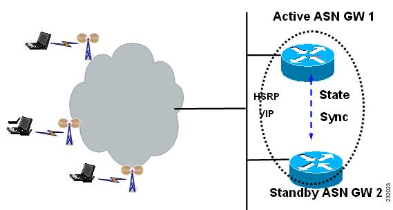
The ASN Gateway Session Redundancy architecture provides user session failover capability in a 1:1 redundancy model, with a standby present for every active ASN Gateway. The active ASN Gateway sends state information to the standby ASN Gateway for state synchronization on a as needed basis. When an active ASN Gateway failure occurs, the standby ASN Gateway has state information needed to provide service to all existing sessions. It then takes over as the active ASN Gateway and begins servicing user sessions, thus providing session redundancy. When the previously active ASN Gateway comes back online, it takes over as standby for the now active ASN Gateway, and obtains state information for all existing sessions from it.
The ASN Gateway is hosted on the SAMI blade, and only card to card redundancy will be supported. In other words, failure of a single processor unit on SAMI will result in the entire card being switched over.
ASN Gateway Session Redundancy and High Availability Infrastructure
The ASN Gateway Session Redundancy is based on the Cisco IOS Hot Standby Routing Protocol (HSRP), the Cisco IOS Check-point Facility (CF) and Redundancy Framework (RF), and Stream Control Transmission Protocol (SCTP) to provide inter-device redundancy and high availability. The Figure 2-1 shows the system view of the ASN Gateway SR with relation to the IOS HA infrastructure.
Figure 2-1
Session Redundancy on the ASN Gateway
Subscriber Management
Subscriber information includes session and flows associated with a subscriber context, and is created, updated, or eventually deleted.
Subscriber information includes the following details:
•
•
•
•
•
•
•
DHCP and AAA
The ASN Gateway supports DHCP relay mode and keeps track of client IP addresses allocated by DHCP servers (and the associated server IP addresses) so that it can relay future DHCP messages from clients to the servers. The client IP address and DHCP server IP address are saved in the subscriber context and are synced to the standby. Once the standby becomes active, it continues to relay DHCP messages from a client to the right server (there can be multiple servers configured: primary/secondary).
IOS AAA is not HA-aware at the moment, so the sync of AAA-related information is part of the session replication.
Bulk Synchronization
Bulk synchronization occurs after the standby is booted up. During this stage, the stateful data of all the established sessions/flows is transferred to the standby. Additionally, all the sessions/flows are recreated to the state that a session/flow is ready to switch user traffic without losing packets (or a very minimal loss) once switchover occurs.
This process can take some time if the number of sessions/flows is big. Sessions/flows are synched to the standby one by one. Once a session/flow is synched to the standby, it is considered bulk-sync complete and is moved to the dynamic queue. It is then ready for dynamic synching upon future events on this session/flow. During this process, sessions/flows continue to be created, modified, or deleted on the active. Thus bulk synching and dynamic synching co-exist until bulk-synching for all sessions/flows is complete. But dynamic synching for a session/flow will not start until its bulk synching is complete first.
Dynamic synching is given priority over bulk synching to maintain consistency and same state for a session/flow between active and standby. This also optimizes the bulk-sync process due to a session/flow state change. For example, a session is established when bulk-sync starts, but is deleted before bulk-sync is initiated for it. As a result, the bulk-sync for this session is not needed anymore as the bulk-sync proceeds.
Dynamic Synchronization
In order for the standby to take over processing from the active in case of a failure, information regarding all sessions and flows on the active are dynamically synchronized to the standby at well defined synchronization points. Separate TLVs are used to synchronize session, flow, and path related information. Dynamic syncing happens for new session/flow events after the standby is at hot-standby state, and after bulk-sync is complete.
The following list identifies current synchronization points:
•
•
•
•
•
•
•
Configuring Session Redundancy
The following configuration tasks are required before you can configure session redundancy:
•
•
•
•
•
To configure session redundancy on the ASN Gateway, perform the following tasks:
Configuration Example
This configuration is for AAA only.
On the Active ASN Gateway
---------------------------------------------------------------
!interface Loopback192ip address 192.168.0.70 255.255.255.255!!aaa group server radius car-sgserver 1.8.70.99 auth-port 1812 acct-port 1813!aaa authentication dot1x car_auth_list group car-sgaaa accounting network car_acct_list start-stop group car-sg!!ip radius source-interface Loopback192radius-server host 1.8.70.99 auth-port 1812 acct-port 1813radius-server key r6AAAradius-server vsa send accounting wimaxradius-server vsa send authentication wimax!On the Standby ASN Gateway
---------------------------------------------------------------
!interface Loopback192ip address 192.168.0.70 255.255.255.255!!aaa new-model!!aaa group server radius car-sgserver 1.8.70.99 auth-port 1812 acct-port 1813!aaa authentication dot1x car_auth_list group car-sgaaa accounting network car_acct_list start-stop group car-sg!!ip radius source-interface Loopback192radius-server host 1.8.70.99 auth-port 1812 acct-port 1813radius-server key r6AAAradius-server vsa send accounting wimaxradius-server vsa send authentication wimaxSample Configuration of ASN Gateway: Active
interface GigabitEthernet0/0.70description to AAA/DHCPencapsulation dot1Q 70ip address 1.8.70.147 255.255.255.0standby 70 ip 1.8.70.70standby 70 follow P7_REDUNDANCY
Note
This configuration example includes information about DHCP:
interface Loopback102ip address 102.0.0.1 255.255.255.0!user-group domain eaptls.com2aaa accounting method-list AAA-ACC1aaa authentication method-list AAA-AUTHN1dhcp gateway address 102.0.0.1dhcp server primary 27.0.0.8service-flow pre-defined isf profile sf3service-flow pre-defined secondary 1 profile sf4vrf VRF_2Authentication
A subscriber is authenticated using EAP on the active before the sessions/flows are recreated on the standby. The associated MSK, AK context and other credentials need to be transferred to the standby, along with the session stateful data. If geographic redundancy is deployed, this data must be protected. If the standby becomes active after a switchover, and if the same subscriber is re-authenticated on the new active, it follows the same authentication procedure as on the previous active.
Accounting
The accounting start, stop and interim update are only sent from the active. The standby never sends accounting records until it becomes active.
As part of the session/flow recreation on the standby, the IOS AAA database is populated with accounting records for each session/flow. For example, the "class" attribute and accounting session ID are synched from the active to the standby, and are saved to the related accounting record. This ensures that once the standby becomes active, it can send accounting records with the right info.
Synchronization of accounting counters is a function of the AAA interim accounting update feature. If the AAA interim accounting update feature is enabled, then the active ASN Gateway sends accounting records to AAA server. And the same event is used as a trigger to initiate a FLOW UPDATE event (which carries accounting counters the same as were sent to AAA server). Conversely, if this feature is disabled on the active, since there is not going to be an accounting update to AAA, there is an absence of triggers to send the accounting update synchronization message to standby. By itself, the ASN Gateway SR feature does not implement triggers to synchronize accounting counters.
The accounting session ID is a key attribute used in accounting events (start, stop, interim) and is used to collaborate records on the AAA server. It is a 4-byte unassigned integer, and is assigned uniquely within a ASNWG and increased sequentially until it rolls over. To ensure the new active can continue to generate unique accounting session IDs upon switchover, the new accounting session ID starts from the latest accounting session ID on the prior active.
Subscriber IP Address
Currently, the subscriber IP address is assigned by the DHCP server and a host route is inserted for it. When the standby recreates the subscriber session, the same host route is also inserted on the standby. The standby will not relay any DHCP messages between the DHCP client and the server until it becomes active.
QoS
For ASN Gateway Release 1.0, after a flow is created and the QoS parameters for the flow are sent to the BS, the ASN Gateway active synchronizes all the QoS parameters to the standby. Out of all of the parameters, the DSCP code for a flow synched to the standby is used to mark the packets once it becomes active.
Statistics and Counters
Statistics and counters are not synched to the standby. Instead, the standby rebuilds them as it processes stateful data from the active to create, modify, and delete sessions/flows. For example, the number of sessions/flows on the standby is updated as the standby processes session/flow creation and deletion. The number of received R6 messages on the standby is accumulated from the moment it becomes active and starts to receive R6 messages.
ASN Gateway Load Balancing
When a load balancer is running, it uses the loading information of all the ASN Gateways to select one of them, and forwards an incoming NetEntry message from the BS (with regard to a SS/MS) to the selected ASN Gateway.
When Dynamic Feedback Protocol (DFP) is configured, an active ASN Gateway periodically sends its loading information to the load balancer. A standby ASN Gateway does not send feedback and does not have accurate loading information because it does not process R6 messages and handle user traffic. Once a standby becomes active, it gradually builds accurate load as it processes R6 messages and handles user traffic. So there is an adjusting period before it can send back feedback about its current accurate load.
Data Path and GRE
The data path for a flow is recreated on the standby. The GRE keys for both the upstream and downstream of a flow are synched to the standby. Upon switchover, the new active ensures that any new GRE key allocated locally must not collide with any in-use GRE keys allocated by the previous active.
Version Control
Upgrading from the immediate lower software version to a higher version is supported. Downgrading of software version is not supported. For example, if a redundant pair of ASN Gateways runs on version A and the next immediate software version is version B, then upgrading from version A to B is supported (but not from B to A). This requires that the higher version understands the stateful data synched from a lower version.
Limitations
The following limitations exist in the Session Redundancy feature on the ASN Gateway:
•
This is configurable, and depends upon the AAA interim accounting update feature to be enabled. If the AAA interim accounting feature is disabled, then the default behavior of ASN Gateway SR is to not synchronize accounting data/payload counters. This may lead to under charging. For example, if a switchover occurs between two consecutive interim updates, the counts accumulated on the active after the previous interim update are lost, since the new interim update sends only the counts that are accumulated on the new active. Additionally, a STOP could be lost right before the switchover.
Note
Note
•
Although SCTP provides reliable transport, the stateful data used to replicate a session can be lost due to congestion or max retrials. In this case, the session is not recreated on the standby. In case there is a switchover, this session is lost.
•
For the same reason as above, if a stateful data for a session deletion is lost, then the session is not deleted from the standby while it's gone on the active.
–
–
•
If a call setup is in progression but before reaching the first synching point and if there is a switchover, the call setup is aborted, and the subscriber has to retry the call.
Switchover
When switchover occurs, a trap is generated and sent to the NMS system to indicate that the active unit has failed, and the standby has taken over as active. The following behavior is expected:
•
•
•
•
•
The following list identifies events which will cause a switchover:
•
•
•
–
This command is used to switch activity from current active to current hot standby. Issuing the command causes the current router to reload, the current hot standby to become active, and when the current active router comes back up it assumes the role of hot standby.
–
This is normal router reload command that causes switchover. The current active router will reload, and the current hot standby will become active.
ASN Gateway Load Balancing
The purpose of load balancing is scalability of the ASN Gateway without distributing intelligence across base stations. This scalability is provided by load balancing across a set of ASN Gateways, while representing the cluster as a single ASN Gateway from the perspective of the BS. Thus, the base station will have a single point of contact. And any new ASN Gateway that is added to the system will not impact the base station provisioning.
Note
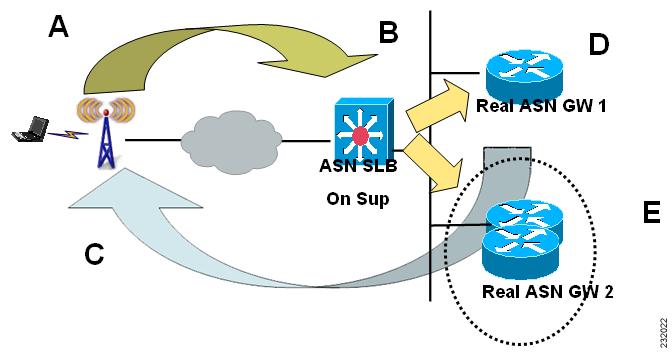
ASN Gateway Load Balancing is based on the IOS Server Load Balancing (SLB) feature. BSs are configured with the virtual IP address of the SLB as the ASN Gateway ID. The ASN Gateway selection flow for load balancing is illustrated below. Both dispatch mode and directed mode are supported. DFP is supported for the SLB to discover the load on the real ASN Gateways.
Note
The session created on SLB, when the initial context request is processed, is maintained for a configurable time period to handle the re-transmission. During this period, if a re-transmission of context request is detected for a given MS/SS, SLB directs the re-transmission request to the same real ASN Gateway, that was selected for the first context request.
DFP is supported for the SLB to discover the load on the real ASN Gateways. Each real ASN Gateway has a limit on the number of maximum sessions it supports. Real ASN Gateway calculated load on itself is based on the existing number of sessions versus the maximum sessions that it can support, memory usage, and bandwidth usage and reports the load to SLB. SLB directs the initial context request to one of the real ASN Gateways based on either the round robin or least connections method. An ASN Gateway will not accept any more sessions if its load as calculated by DFP is 100%. Thus, this mechanism also supports CAC.
Figure 2-2
Server Load Balancing on the ASN Gateway
ASN Gateway Selection
•
•
•
Modes of Operation
There are two operation modes on the ASN Gateway:
•
•
In both modes the selected ASN Gateway sends the pre-attachment response.
Configuring Load Balancing
This section lists configuration details regarding server load balancing. These configuration details are mainly for Directed Mode unless otherwise specified.
Load Balancing Configuration Task List
This section lists the tasks used to configure load balancing. Required and optional tasks
are indicated.
1.
a.
b.
c.
2.
a.
b.
Configuring Cisco IOS SLB for Load Balancing
This section describes how to configure a Server Farm and a Real Server. To configure a Cisco IOS SLB server farm, use the following commands, beginning in global configuration mode:
Sample Configuration
ip slb serverfarm ASNGW-SR-SFnat serverprobe PINGPROBE!real 11.11.11.50weight 0inservice!real 11.11.11.70weight 0inserviceConfiguring Real ASN Gateway
Configuring the ASN Gateway for Load Balancing
To configure load balancing on the ASN Gateway, complete the tasks in the following sections:
•
•
Configuring a Loopback Interface for SLB
To enable load balancing, a loopback interface must be configured with the same IP address as thevirtual server on the Cisco IOS SLB on each ASN Gateway in a farm.
To create a loopback interface, use the following commands, beginning in global configuration mode:
Configuring the ASN Gateway as a DFP Agent
To define the port number to be used by the DFP manager (the Cisco IOS SLB in this instance) to connect to the DFP agent; enter the following commands in order, beginning in global configuration mode:
Sample Configuration
ip dfp agent agwport 5555inserviceTo configure load balancing on the ASN Gateway, perform the following task:
ASN Gateway Configuration Example
Please note that following sample configuration applies only to SAMI platform.
SLB Related Configuration of Supervisor Card
7606-R6-sup720#show running-configuration | section slbip dfp agent slbport 5555ip slb probe PINGPROBE pinginterval 3faildetect 3ip slb serverfarm ASNGW-SR-SFnat serverprobe PINGPROBE!real 11.11.11.50weight 0inservice!real 11.11.11.70weight 0inserviceip slb vserver V-ASNGW-SRvirtual 50.70.80.100 udp 2231 service asn r6serverfarm ASNGW-SR-SFidle asn r6 request 90inserviceip slb dfpagent 11.11.11.50 5555 10 0 5agent 11.11.11.70 7777 10 0 57606-R6-sup720#Sample configuration of real ASN Gateway for above configuration of Supervisor card.
asngw-real-s4p5# show running-configuration | section dfpip dfp agent agwport 5555inserviceasngw-real-s4p5#asngw-real-s4p7#sh runn | section dfpip dfp agent agwport 7777inserviceasngw-real-s4p7#Verifying the Configuration
To verify that load balancing is enabled on the ASN Gateway, perform the following tasks:
Configuration Example
Here is a sample configuration for SLB show commands on the ASN Gateway:
7606-R6-sup720#show ip slb sessions asn r6vserver MSID Base Station real state----------------------------------------------------------------------------7606-R6-sup720#show ip slb sessions asn r6vserver MSID Base Station real state----------------------------------------------------------------------------V-ASNGW-SR 0000AAAAC38ECCCC 50.35.50.1 11.11.11.50 ASNR6_ESTABV-ASNGW-SR 0000AAAAC392CCCC 50.35.50.1 11.11.11.50 ASNR6_ESTABV-ASNGW-SR 0000AAAAC396CCCC 50.35.50.1 11.11.11.50 ASNR6_ESTABV-ASNGW-SR 0000AAAAC39ACCCC 50.35.50.1 11.11.11.50 ASNR6_ESTABV-ASNGW-SR 0000AAAAC39ECCCC 50.35.50.1 11.11.11.50 ASNR6_ESTAB< S N I P P E D >7606-R6-sup720#show ip slb vserver detailV-ASNGW-SR, state = OPERATIONAL, v_index = 7, interface(s) = <any>virtual = 50.70.80.100/32:2231, UDP, service = ASNR6, advertise = TRUEserver farm = ASNGW-SR-SF, delay = 10, idle = 3600asnr6: request idle = 90, Parse error pkt drops= 56,Number of reject responses = 0sticky: <none>sticky: group id = 0synguard counter = 0, synguard period = 0conns = 101, total conns = 509069, syns = 0, syn drops = 0standby group = None7606-R6-sup720#show ip slb realsreal farm name weight state conns-------------------------------------------------------------------11.11.11.50 ASNGW-SR-SF 92 OPERATIONAL 8311.11.11.70 ASNGW-SR-SF 92 OPERATIONAL 187606-R6-sup720#show ip slb serv7606-R6-sup720#show ip slb serverfarmsserver farm predictor nat reals bind id interface(s)--------------------------------------------------------------------------ASNGW-SR-SF ROUNDROBIN S 2 0 <any>7606-R6-sup720#show ip slb sessions asn r6 de7606-R6-sup720#show ip slb sessions asn r6 detailV-ASNGW-SR, client = 50.35.50.1:2231, virtual = 50.70.80.100:2231state = ASNR6_ESTAB, real = 11.11.11.50Key = 0000AAAAC38ECCCC, retry = 1V-ASNGW-SR, client = 50.35.50.1:2231, virtual = 50.70.80.100:2231state = ASNR6_ESTAB, real = 11.11.11.50Key = 0000AAAAC392CCCC, retry = 1V-ASNGW-SR, client = 50.35.50.1:2231, virtual = 50.70.80.100:2231state = ASNR6_ESTAB, real = 11.11.11.50Key = 0000AAAAC396CCCC, retry = 1V-ASNGW-SR, client = 50.35.50.1:2231, virtual = 50.70.80.100:2231state = ASNR6_ESTAB, real = 11.11.11.50Key = 0000AAAAC39ACCCC, retry = 1V-ASNGW-SR, client = 50.35.50.1:2231, virtual = 50.70.80.100:2231state = ASNR6_ESTAB, real = 11.11.11.50Key = 0000AAAAC39ECCCC, retry = 1V-ASNGW-SR, client = 50.35.50.1:2231, virtual = 50.70.80.100:2231state = ASNR6_ESTAB, real = 11.11.11.50< S N I P P E D >7606-R6-sup720#Configuring a Virtual Server
To configure a Cisco IOS SLB virtual server, use the following commands, beginning in global configuration mode:
Sample Configuration
Router-SLB(config)# ip slb vserver V-ASNGW-SRRouter-SLB(config-slb-vserver)# virtual 50.70.80.100 udp 2231 service asn r6Router-SLB(config-slb-vserver)#serverfarm ASNGW-SR-SFRouter-SLB(config-slb-vserver)# idle asn r6 request 90Router-SLB(config-slb-vserver)#inserviceConfiguring DFP Support
You can define Cisco IOS SLB as a DFP manager, as a DFP agent for another DFP manager (such as DistributedDirector), or as both at the same time. Depending on your network configuration, you might enter the commands for configuring Cisco IOS SLB as a DFP manager and the commands for configuring Cisco IOS SLB as a DFP agent on the same device or on different devices.
To configure Cisco IOS SLB as a DFP manager, and to identify a DFP agent with which Cisco IOS SLB can initiate connections, use the following commands, beginning in global configuration mode:
Sample Configuration
Router-SLB(config) # ip slb dfpRouter-SLB(config-slb-dfp)# agent 11.11.11.50 5555 10 0 5Router-SLB(config-slb-dfp)# agent 11.11.11.70 7777 10 0 5Configuring the ASN Gateway
This section describes various other configuration tasks that you need to perform to make the ASN Gateway function properly. It includes the following topics:
•
Configuring SNMP on the ASN Gateway
This section provides information on how to configure Simple Network Management Protocol (SNMP) on the ASN Gateway. It contains the following configuration tasks:
•
•
Configuring SNMP Access in Routers
To set up the community access string to permit access to the Simple Network Management Protocol (SNMP), perform the following tasks:
Configuring SNMP-Server Host
To specify the recipient of an Simple Network Management Protocol notification operation, perform the following tasks:
This command is disabled by default. No notifications are sent. If you enter this command with no keywords, the default is to send all trap types to the host. No informs will be sent to this host.
If no version keyword is present, the default is version 1. The no snmp-server host command with no keywords will disable traps, but not informs, to the host. In order to disable informs, use the no snmp-server host informs command.
Configuring SNMP-Server Trap-Source
To specify the interface (and hence the corresponding IP address) that an Simple Network Management Protocol trap should originate from, perform the following task:
Configuring SNMP Traps
To enable the router to send Simple Network Management Protocol traps or informs (SNMP notifications), perform the following task:
Configuration Examples
The following example enables the router to send all traps to the host specified by the name "myhost.cisco.com", using the community string defined as "public":
snmp-server enable trapssnmp-server host myhost.cisco.com publicThe following example enables the router to send Frame Relay and environmental monitor traps to the host "myhost.cisco.com" using the community string "public":
snmp-server enable traps frame-relaysnmp-server enable traps envmon temperaturesnmp-server host myhost.cisco.com publicThe following example will not send traps to any host. The BGP traps are enabled for all hosts, but the only traps enabled to be sent to a host are ISDN traps (which are not enabled in this example).
snmp-server enable traps bgpsnmp-server host bob public isdnASNGW(config)# [no] logging snmp-authfail
Note
Note
ASNGW(config)# [no] virtual-template snmp
SNMP Configuration Examples on the ASN Gateway
Logging
=========
!logging snmp-authfaillogging queue-limit 100logging buffered 1000000enable password lab!Virtual Template
=============
!no virtual-template snmp!SNMP Traps
==========
snmp-server community private RWsnmp-server trap-source GigabitEthernet0/2snmp-server enable traps snmp authentication linkdown linkup coldstart warmstartsnmp-server enable traps vrrpsnmp-server enable traps ds1snmp-server enable traps ttysnmp-server enable traps eigrpsnmp-server enable traps casasnmp-server enable traps cnpdsnmp-server enable traps pw vcsnmp-server enable traps syslogsnmp-server enable traps isdn call-informationsnmp-server enable traps isdn layer2snmp-server enable traps isdn chan-not-availsnmp-server enable traps isdn ietfsnmp-server enable traps ds3snmp-server enable traps atm subifsnmp-server enable traps channelsnmp-server enable traps imasnmp-server enable traps srpsnmp-server enable traps flash insertion removalsnmp-server enable traps hsrpsnmp-server enable traps configsnmp-server enable traps entitysnmp-server enable traps fru-ctrlsnmp-server enable traps cpu thresholdsnmp-server enable traps config-copysnmp-server enable traps envmonsnmp-server enable traps aaa_serversnmp-server enable traps agwsnmp-server enable traps bgpsnmp-server enable traps ospf state-changesnmp-server enable traps ospf errorssnmp-server enable traps ospf retransmitsnmp-server enable traps ospf lsasnmp-server enable traps ospf cisco-specific state-change nssa-trans-changesnmp-server enable traps ospf cisco-specific state-change shamlink interface-oldsnmp-server enable traps ospf cisco-specific state-change shamlink neighborsnmp-server enable traps ospf cisco-specific errorssnmp-server enable traps ospf cisco-specific retransmitsnmp-server enable traps ospf cisco-specific lsasnmp-server enable traps pim neighbor-change rp-mapping-change invalid-pim-messagesnmp-server enable traps ipmulticastsnmp-server enable traps mvpnsnmp-server enable traps msdpsnmp-server enable traps rsvpsnmp-server enable traps frame-relaysnmp-server enable traps frame-relay subifsnmp-server enable traps ipslasnmp-server enable traps stunsnmp-server enable traps dlswsnmp-server enable traps bstunsnmp-server enable traps pppoesnmp-server enable traps l2tun sessionsnmp-server enable traps l2tun pseudowire statussnmp-server enable traps ipmobilesnmp-server enable traps frame-relay multilink bundle-mismatchsnmp-server enable traps dsp card-statussnmp-server enable traps dsp oper-statesnmp-server enable traps event-managersnmp-server enable traps alarms informationalsnmp-server host 171.71.129.34 publicMIB Support
The ASN Gateway supports a Management Information Base (MIB) that describes objects that enable users and network management to remotely monitor the ASN Gateway using SNMP commands. The ASN Gateway supports two separate MIBs:
One contains global system information and parameters, base-station information, subscriber, flow, traffic and trap notification information.
The second contains information about the R6 signaling protocol information used between the base-station and the ASN Gateway. This includes overall gateway R6 information, and information per base-station.
The ASNGateway MIB variables are not synchronized across a fail-over. Many MIB variables can be recreated on the standby from the synchronized state data. The NMS attempts to handle such a situation, and any inconsistencies in MIB data that result from this approach. The existing RF/CF MIB is also available.
Note
Verifying MIB Support
To display various MIB parameters, perform the following tasks:
Configuration Examples
Here is sample output for the show wimax agw command:
router# show wimax agwAccess network gateway version 0.1, service is enabledAGW listening on UDP control port 2231Maximum Number of base station 500 allowedMaximum Number of subscriber 20000 allowedNumber of signalling paths created 0Number of brearer paths created 0Number of subscribers connected 0Number of sessions created 0Number of flows created 0Traffic Sent 0 packets, 0 bytesTraffic Rcvd 0 packets, 0 bytesHere is samle output for the showwimax agw user-group command:
router# show wimax agw user-groupAGW User-Group-ListThere are 3 user-groups configured in list wimaxUser group domain name anyService mode operationalSessions 0 associatedTraffic Sent 0 packets, 0 bytesTraffic Recevied 0 packets, 0 bytesIngress Address filtering 0 packets, 0 bytesUser group domain name ciscoService mode operationalSessions 0 associatedTraffic Sent 0 packets, 0 bytesTraffic Recevied 0 packets, 0 bytesIngress Address filtering 0 packets, 0 bytesUser group domain name unauthenticatedService mode operationalSessions 0 associatedTraffic Sent 0 packets, 0 bytesTraffic Recevied 0 packets, 0 bytesIngress Address filtering 0 packets, 0 bytesrouter#show wimax agw user-group brief ?Name Sessions Pkts-Tx Bytes-Tx Pkts-Rx Bytes-Rx VRFany 0 0 0 0 0cisco 0 0 0 0 0unauthenticated 0 0 0 0 0router#show wimax agw user-group any ?brief Brief output| Output modifiers<cr>router#show wimax agw user-group anyUser group domain name any--------------------------------------Service mode operationalSessions 0 associatedTraffic Sent 0 packets, 0 bytesTraffic Recevied 0 packets, 0 bytesIngress Address filtering 0 packets, 0 bytesrouter#show wimax agw user-group any briefName Sessions Pkts-Tx Bytes-Tx Pkts-Rx Bytes-Rx VRFany 0 0 0 0 0router#show wimax agw user-group name ?WORD Enter User-group Namerouter#show wimax agw user-group name cisco ?brief Brief output| Output modifiers<cr>router#show wimax agw user-group name ciscoUser group domain name cisco--------------------------------------Service mode operationalSessions 0 associatedTraffic Sent 0 packets, 0 bytesTraffic Recevied 0 packets, 0 bytesIngress Address filtering 0 packets, 0 bytesrouter#show wimax agw user-group name cisco brief ?| Output modifiers<cr>router#show wimax agw user-group name cisco briefName Sessions Pkts-Tx Bytes-Tx Pkts-Rx Bytes-Rx VRFcisco 0 0 0 0 0router#show wimax agw user-group unauthenticated ?brief Brief output| Output modifiers<cr>router#show wimax agw user-group unauthenticatedUser group domain name unauthenticated--------------------------------------Service mode operationalSessions 0 associatedTraffic Sent 0 packets, 0 bytesTraffic Recevied 0 packets, 0 bytesIngress Address filtering 0 packets, 0 bytesasn#sh wimax agw user-group unauthenticated basn#sh wimax agw user-group unauthenticated brief ?| Output modifiers<cr>router#show wimax agw user-group unauthenticated briefName Sessions Pkts-Tx Bytes-Tx Pkts-Rx Bytes-Rx VRFunauthenticated 0 0 0 0 0Here is sample output for the show wimax agw statistics command:
router# show wimax agw statisticsAGW StatisticsMessage function type Undefined(0/0x0)Message function type Data Path(3/0x3)Message type Deregistration Request(4/0x4)Number of messages sent 0Number of messages received 0Number of messages resent 0Message type Deregistration Response(5/0x5)Number of messages sent 0Number of messages received 0Number of messages resent 0Message type Deregistration Ack(6/0x6)Number of messages sent 0Number of messages received 0Number of messages resent 0Message type Registration Request(12/0xC)Number of messages sent 0Number of messages received 0Number of messages resent 0Message type Registration Response(13/0xD)Number of messages sent 0Number of messages received 0...Here is sample output for the show wimax agw statistics dhcp-relay command:
router# show wimax agw statistics dhcp-relayAGW DHCP StatisiticsTx to DHCP server Discover 0, Request 0Tx to DHCP server Release 0, Decline 0Tx to DHCP server Inform 0Rx from DHCP server Offer 0, Ack 0Rx from DHCP server Nak 0, Unknown 0This output gives the statistics of DHCP messages that are relayed through the ASN Gateway. If the ASN GW happened to initiate any DHCP messages, these counters are not incremented.
Here is sample output for the show wimax agw statistics internal command:
Router# show wim agw statistics internalLast clearing of "show wimax agw statistics internal" counters neverSignalling plane related statisticsSignal packets dropped service not ready 0Configuration related statisticsService flow profile not found 0QoS profile not found 0Classifier profile not found 0Handoff related statisticsTotal handoffs succeeded 0Total handoff failed 0Total cmac key update succeeded 0Total cmac key update failed 0Total security key exchange succeeded 0Total security key exchange failed 0Router#Features Not Supported
The following features are not supported in this release:
•
•
•
Data Plane
The data plane is started after successful completion of the EAP authentication phase. GRE tunnel exists between the BS and ASN Gateway, and a unique GRE key is used for the data path corresponding to each service flow. There is a GRE key allocated in each direction.
The following data plane features are supported on the ASN Gateway:
GRE Keying
A GRE key is allocated per service flow in each direction. The GRE keys are exchanged using the RR-Request used to create the Data Path bearer. The GRE keys that correspond to the ASN Gateway are allocated by the ASN Gateway and sent to the BS during creation of the service flow using the RR-Request. Similarly, the GRE key values corresponding to the BS are allocated by the BS and sent to the ASN Gateway using the RR-Response message.
During Inter-BS mobility, new keys are allocated by the Base-station. The ASN Gateway keeps the same GRE keys.
The ASN Gateway allocates the GRE keys such that the values are not assigned immediately upon release.
VRF Support
A user-group can be configured with virtual route forwarding (VRF) support. This allows you to create an internal VRF entity to connect all traffic to/from the specific user-group.
Restrictions
The following restriction apply in Cisco ASN Gateway Release 1.0:
•
–
–
–
!interface Virtual-Template1description ASNGW-VTip unnumbered Loopback0encapsulation agwno logging event link-statusaccess-point-list wimaxend