Downloads |
 Feedback Feedback
|
Table Of Contents
Cisco NM-1A-OC3-POM Network Module
Prerequisites for ATM-OC3-POM Modules
Restrictions for ATM-OC3-POM Modules
Information About ATM-OC3-POM Modules
Classes of Service and Transmit Priority on the ATM-OC3-POM Module
How to Configure ATM-OC3-POM Modules
Mapping a Protocol Address to a PVC
Configuring the AAL and Encapsulation Type
Configuring PVC Traffic Parameters
Configuring Communication with the ILMI
Configuring the PVC That Performs SVC Call Setup
Customizing the ATM-OC3-POM Module
Troubleshooting High Latency and Output Drop Rates in Low Bandwidth PVCs
Configuration Example for ATM-OC3-POM Modules
An Example of the Output of the show controller Command
Explanations of Principal Command Outputs
Feature Information for ATM-OC3-POM Modules
Cisco NM-1A-OC3-POM Network Module
First Published: July 22, 2005Last Updated: April 10, 2008This document provides configuration tasks for the Cisco NM-1A-OC3-POM network module hardware feature supported on Cisco 3800 series integrated services routers.
The Cisco NM-1A-OC3-POM network module is a high performance single-width, single-port ATM network module, utilizing an optical carrier level 3 (OC-3) link. The ATM interface is a small form-factor pluggable (SFP) optical port. Fiber-optic cables to the network are attached to an SFP module that is inserted into the SFP port. The network module has 3 modes of operation. The mode of operation is determined by the SFP module that is used. The modes of operation and usable SFP modules are:
•
Multimode (MM)
–
–
•
–
–
•
–
–
This hardware feature introduces one new IOS debug command.
Contents
The following sections provide information about the Cisco ATM-OC3-POM modules.
•
•
•
•
•
•
Prerequisites for ATM-OC3-POM Modules
The following are prerequisites to configuring Cisco ATM-OC3-POM modules:
•
Restrictions for ATM-OC3-POM Modules
The following restrictions apply to the Cisco ATM-OC3-POM modules.
•
•
–
–
Information About ATM-OC3-POM Modules
To configure the Cisco ATM-OC3-POM modules, you should understand the following concepts:
•
Virtual Circuits
A virtual circuit (VC) is a point-to-point connection between remote hosts and routers. A VC is established for each ATM end node with which the router communicates. The characteristics of the VC are established when the VC is created and include the following:
•
–
–
–
–
–
Note
•
•
–
–
–
–
–
–
–
–
Each VC supports the following router functions:
•
•
•
•
By default, CEF switching is enabled on all OC-3 module interfaces. These switching features can be turned off with interface configuration commands. Flow must be explicitly enabled for each interface.
Permanent Virtual Circuits
To use a permanent virtual circuit (PVC), configure the PVC in both the router and the ATM switch. PVCs remain active until the circuit is removed from either configuration. When a PVC is configured, all of the configuration options are passed on to the OC-3 module. You can write these PVCs into nonvolatile RAM (NVRAM); they are used when the system image is reloaded.
Some ATM switches might have point-to-multipoint PVCs that do the equivalent of broadcasting. If a point-to-multipoint PVC exists, it can be used as the sole broadcast PVC for all multicast requests.
Like Frame Relay, ATM supports two types of interface: point-to-point and multipoint. The one you choose determines whether you need to use the configuration commands that ensure IP to ATM mappings.
Switched Virtual Circuits
ATM switched virtual circuits (SVCs) are created and released dynamically, providing user bandwidth on demand. This service requires a signaling protocol between the router and the switch.
The ATM signaling software provides a method of dynamically establishing, maintaining, and clearing ATM connections at the User-Network Interface (UNI). The ATM signaling software conforms to the ATM Forum UNI 4.1 specification.
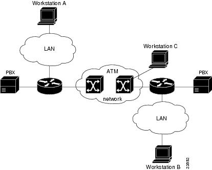
In UNI mode, the user is the router, and the network is an ATM switch. This is an important distinction. The Cisco router does not perform ATM-level call routing. Instead, the ATM switch does the ATM call routing, and the router routes packets through the resulting circuit. The router is viewed as the user and the LAN interconnection device at the end of the circuit, and the ATM switch is viewed as the network.
Figure 1 illustrates the router position in a basic ATM environment. The router is used primarily to interconnect LANs through an ATM network. Workstation C is connected directly to the destination ATM switch. You can connect not only routers to ATM switches, but also any network device with an ATM interface that conforms to the ATM Forum UNI specification.
Figure 1 Basic ATM Environment
Classes of Service and Transmit Priority on the ATM-OC3-POM Module
The transmit priority determines which queued cell is chosen to be transmitted out of an interface during a cell time slot and ensures that real-time ATM service classes, which typically offer more robust QoS and traffic guarantees, have a higher likelihood of access to the next cell time slot. Table 1 lists the ATM service classes and their default transmit priorities on the ATM-OC3-POM module.
Table 1 ATM Classes of Service and Default Transmit Priorities on the ATM-OC3-POM Module
CBR, OAM cells and signaling
0
VBR-rt, VBR-nrt
1
ABR
2
UBR, UBR+
3
How to Configure ATM-OC3-POM Modules
See the following sections for configuration tasks for the Cisco ATM-OC3-POM modules.
•
•
Configuring OC-3
To configure the ATM-OC3-POM module for OC-3 operation, perform the following tasks beginning in privileged EXEC mode.
SUMMARY STEPS
1.
2.
3.
4.
5.
DETAILED STEPS
Configuring PVCs
To use a PVC, you must configure the PVC into both the router and the ATM switch. PVCs remain active until the circuit is removed from either configuration.
To configure a PVC, perform the tasks in the following sections.
•
•
•
Creating a PVC
To create a PVC on the ATM interface and enter interface-ATM-VC configuration mode, use the following command beginning in interface configuration mode:
The range of values for vpi is 0-255. The range of values for vci is 1-65535.
Note
Once you specify a name for a PVC, you can reenter the interface-ATM-VC configuration mode by simply entering pvc name.
Note
Mapping a Protocol Address to a PVC
The ATM interface supports a static mapping scheme that identifies the network address of remote hosts or routers. This section describes how to map a PVC to an address, which is a required task for configuring a PVC.
To map a protocol address to a PVC, use the following command in interface-ATM-VC configuration mode:
Router(config-if-atm-vc)# protocol protocol protocol-address [[no] broadcast]
Maps a protocol address to a PVC.
Note
Configuring the AAL and Encapsulation Type
To configure the ATM adaptation layer (AAL) and encapsulation type, use the following command beginning in interface-ATM-VC configuration mode:
Router(config-if-atm-vc)# encapsulation aal5encap
Configures the ATM adaptation layer (AAL) and encapsulation type.
For a list of AAL types and encapsulations supported for the aal-encap argument, refer to the encapsulation aal5 command in the "ATM Commands" chapter of the Cisco IOS Wide-Area Networking Command Reference. The global default is AAL5 with SNAP encapsulation.
Configuring PVC Traffic Parameters
The supported traffic parameters are part of the following service categories: Available Bit Rate (ABR), Unspecified Bit Rate (UBR), UBR+ (on SVCs only), Constant Bit Rate (CBR), non-realtime Variable Bit Rate (VBR-nrt), and realtime Variable Bit Rate (VBR-rt). Only one of these categories can be specified per PVC connection so if a new one is entered, it will replace the existing one.
To configure PVC traffic parameters, use one of the following commands beginning in interface-ATM-VC configuration mode:
The -pcr and -mcr arguments are the peak cell rate and minimum cell rate, respectively. The -scr and -mbs arguments are the sustainable cell rate and maximum burst size, respectively.
For ABR VCs, you can optionally configure the amount that the cell transmission rate increases or decreases in response to flow control information from the network or destination. To configure this option, use the following command in interface-ATM-VC configuration mode:
Enabling Inverse ARP
Inverse ARP is enabled by default when you create a PVC using the pvc command. Once configured, a protocol mapping between an ATM PVC and a network address is learned dynamically as a result of the exchange of ATM Inverse ARP packets.
Inverse ARP is supported on PVCs running IP or IPX and no static map is configured. If a static map is configured, Inverse ARP will be disabled.
To enable Inverse ARP on an ATM PVC, use the following commands beginning in global configuration mode:
SUMMARY STEPS
1.
2.
3.
4.
DETAILED STEPS
Address mappings learned through Inverse ARP are aged out. However, mappings are refreshed periodically. This period is configurable using the inarp command, which has a default of 15 minutes.
You can also enable Inverse ARP using the protocol command. This is necessary only if you disabled Inverse ARP using the no protocol command. For more information about this command, refer to the "ATM Commands" chapter in the Cisco IOS Wide-Area Networking Command Reference.
Configuring SVCs
To use SVCs, complete the tasks in the following sections:
•
•
Configuring Communication with the ILMI
In an SVC environment, you must configure a PVC for communication with ILMI so the router can receive SNMP traps and new network prefixes. The recommended vpi and vci values for the ILMI PVC are 0 and 16, respectively. To configure ILMI communication, use the following command in interface configuration mode:
Router(config-if)# pvc [name] 0/16 ilmi
Creates an ILMI PVC on an ATM main interface.
Note
Once you have configured an ILMI PVC, you can optionally enable the ILMI keepalive function by using the following command in interface configuration mode:
Router(config-if)# atm ilmi-keepalive [seconds]
Enables ILMI keepalives and sets the interval between keepalives.
No other configuration steps are required.
ILMI address registration for receipt of SNMP traps and new network prefixes is enabled by default. The ILMI keepalive function is disabled by default; when enabled, the default interval between keepalives is 3 seconds.
Configuring the PVC That Performs SVC Call Setup
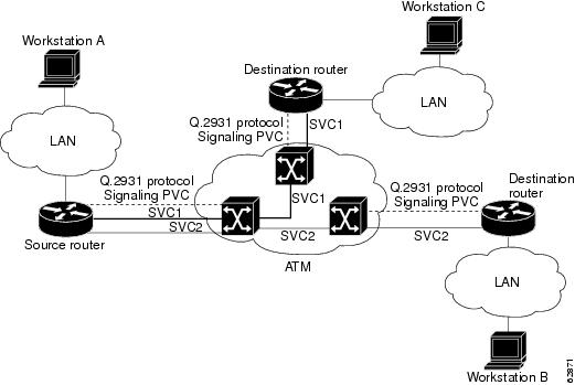
ATM uses out-of-band signalling. One dedicated PVC exists between the router and the ATM switch, over which all SVC call establishment and call termination requests flow. After the call is established, data transfer occurs over the SVC, from router to router. The signalling that accomplishes the call setup and teardown is called Layer 3 signalling or the Q.2931 protocol.
For out-of-band signalling, a signalling PVC must be configured before any SVCs can be set up. Figure 2 illustrates that a signalling PVC from the source router to the ATM switch is used to set up two SVCs. This is a fully meshed network; workstations A, B, and C all can communicate with each other.
Figure 2 One or More SVCs Require a Signalling PVC
To configure the signalling PVC for all SVC connections, use the following command in interface configuration mode:
Router(config-if)# pvc [name] vpi/vci qsaal
Configures the signalling PVC for an ATM main interface that uses SVCs.
Note
The VPI and VCI values must be configured consistently with the local switch. The standard value for VPI and VCI are 0 and 5, respectively.
Configuring the NSAP Address
Every ATM interface involved with signalling must be configured with a network service access point (NSAP) address. The NSAP address is the ATM address of the interface and must be unique across the network.
To configure an NSAP address, complete the tasks described in one of the following sections:
•
•
Configuring the ESI and Selector Fields
If the switch is capable of delivering the NSAP address prefix to the router by using ILMI, and the router is configured with a PVC for communication with the switch via ILMI, you can configure the endstation ID (ESI) and selector fields using the atm esi-address command. The atm esi-address command allows you to configure the ATM address by entering the ESI (12 hexadecimal characters) and the selector byte (2 hexadecimal characters). The NSAP prefix (26 hexadecimal characters) is provided by the ATM switch.
To configure the router to get the NSAP prefix from the switch and use locally entered values for the remaining fields of the address, use the following commands beginning in interface configuration mode:
SUMMARY STEPS
1.
2.
3.
DETAILED STEPS
The recommended vpi and vci values for the ILMI PVC are 0 and 16, respectively.
You can also specify a keepalive interval for the ILMI PVC. See the "Configuring Communication with the ILMI" section earlier in this chapter for more information.
Configuring the Complete NSAP Address
When you configure the ATM NSAP address manually, you must enter the entire address in hexadecimal format because each digit entered represents a hexadecimal digit. To represent the complete NSAP address, you must enter 40 hexadecimal digits in the following format:
XX.XXXX.XX.XXXXXX.XXXX.XXXX.XXXX.XXXX.XXXX.XXXX.XX
Note
Because the interface has no default NSAP address, you must configure the NSAP address for SVCs. To set the ATM interface source NSAP address, use the following command in interface configuration mode:
Router(config-if)# atm nsap-address nsap-address
Configures the ATM NSAP address for an interface.
The atm nsap-address and atm esi-address commands are mutually exclusive. Configuring the router with the atm nsap-address command negates the atm esi-address setting, and vice versa. For information about using the atm esi-address command, see the preceding section "Configuring the ESI and Selector Fields."
Creating an SVC
To create an SVC, use the following commands beginning in interface configuration mode:
SUMMARY STEPS
1.
2.
3.
DETAILED STEPS
Once you specify a name for an SVC, you can reenter interface-ATM-VC configuration mode by simply entering the svc name command; you can remove an SVC configuration by entering the no svc name command.
For a list of AAL types and encapsulations supported for the aal-encap argument, refer to the encapsulation aal5 command in the "ATM Commands" chapter of the Cisco IOS Wide-Area Networking Command Reference. The default is AAL5 with SNAP encapsulation.
Customizing the ATM-OC3-POM Module
You can customize the ATM-OC3-POM module. The features you can customize have default values that will probably suit your environment and not need to be changed. However, you might need to enter configuration commands, depending on the requirements for your system configuration and the protocols you plan to route on the interface. Perform the tasks in the following sections if you need to customize the ATM-OC3-POM module:
Setting the MTU Size
Each interface has a default maximum packet size or maximum transmission unit (MTU) size. For ATM interfaces, this number defaults to 4470 bytes. The maximum is 9188 bytes for the AIP and NPM, 17969 for the ATM port adapter, and 17998 for the ATM-CES port adapter. The MTU can be set on a per-sub-interface basis as long as the interface MTU is as large or larger than the largest subinterface MTU.
To set the maximum MTU size, use the following command in interface configuration mode:
Setting the Loopback Mode
To loop all packets back to your ATM interface instead of to the network, use the following command in interface configuration mode:
To loop the incoming network packets back to the ATM network, use the following command in interface configuration mode:
Troubleshooting High Latency and Output Drop Rates in Low Bandwidth PVCs
When the bandwidth of a PVC is 10 Mbps or less, there may be high latency of large packets going through the interface queue. Bursty packets in a low bandwidth PVC may also exhibit high latency. This problem may be corrected by adjusting the queue depth of the PVC queue within the SAR.
The SAR mechanism has a queue for each PVC. Each PVC queue has two thresholds associated with it called the high watermark and low watermark. These watermarks define the number of cells the queue can hold. The high and low watermark settings define the depth of the PVC interface queue.
The high watermark is a threshold that triggers a flow-off signal and the low watermark is a threshold that triggers a flow-on signal. The high watermark is the maximum number of cells that can be in the PVC queue for the SAR before a flow-off signal is sent to the host.
If packets are being queued at the host because the flow-off signal has been sent, when the number of cells in the PVC queue reaches the low watermark threshold a flow-on signal is sent to the host. The flow-on signal restarts the packet flow from this PVC to the SAR.
For example, after router startup the flow signal defaults to on. If the number of cells in the PVC queue for the SAR is 35, the high watermark is 50, and the low watermark is 10, packets of all classes flow from the PVC to the SAR. If the number of cells increases to 50, the high watermark triggers the flow-off signal, which stops packet flow for all packets. Packet flow is not restarted until the number of cells decreases to 10, when the low watermark triggers the flow-on signal.
Note
If it is necessary to better control queuing latency or obtain better TCP performance for a PVC, modify the watermark values for it by using the queue-depth command. This command will set the high watermark and low watermark levels for the PVC queue.
Note
To configure the queue depth of a PVC, enter the command sequence given below, beginning in the global configuration mode.
Restrictions
Cisco recommends using default values of the watermarks whenever possible, keeping the use of the queue-depth command to an absolute minimum.
Cisco does not recommend altering the default watermark values when sending small time-sensitive high priority packets.
The queue- depth command is to be used only when the PVC has a bandwidth of 10 Mbps or less, for packets experiencing large delays, and in cases where LLQ is not used.
SUMMARY STEPS
1.
2.
3.
DETAILED STEPS
If you decide to use the queue-depth command, Cisco recommends that the high watermark should not exceed 400. The low watermark must be less than the high watermark.
Use the no form of the queue-depth command to restore default values.
Router(config-if-atm-vc)# no queue-depth
Restores default values of watermarks to the SAR for the selected PVC.
•
•
Configuration Example for ATM-OC3-POM Modules
This section shows how to configure the ATM-OC3-POM module.
Router# configure terminalRouter(config)# interface ATM1/0Router(config-if)# ip address 10.1.1.1 255.255.255.0Router(config-if)# load-interval 30Router(config-if-atm-vc)# atm pvp 10 10000Router(config-if-atm-vc)# no atm ilmi-keepaliveRouter(config-if-atm-vc)# pvc 1/1Router(config-if-atm-vc)# protocol ip 10.1.1.2 broadcastRouter(config-if-atm-vc)# exitRouter(config-if)#Verifying the Configuration
Use the show controller command to verify the configuration of the ATM-OC3-POM module. Explanations of principal outputs of the command are given after the example below.
An Example of the Output of the show controller Command
router# show controller atm 1/0Interface ATM1/0 is upHardware is CX27470 ATMOC3hwidb=0x658F2E60, sardb=0x65906B90, interrupts=1500391slot 1, unit 1, subunit 0PM Build Version: Build ID 0x3976, Version 0x11753E31, Password 0xEE8AC1CEPM Running Version: 1.6.0.2.1Current (cx27470_t)sardb:Buffs with Host 0x7Max Buffs with Host 0x4DMax Pkts Hndld 0x0Command Indication Queue (0x2D91B5C0)Queued (0), ExpSeq (0xB7), Sent (0x14C9DA), Acked (0x14C9DA)Cmds Timed Out 0x0, Cmds no buffs 0x0Packet Indication Queue (0x2E706200)NextEntry (0x1CF0), ExpSeq (0x1)Flow Indication Queue (0x2E726240)NextEntry (0x0), ExpSeq (0x1)Count/Event Indication Queue (0x2E72A280)NextEntry (0x3), ExpSeq (0x4)CX27470 Interface Info:RSY Interface No (0x1), Interface ID (0x101), Status (OPEN)SEG Interface No (0x2), Interface ID (0x202), Status (OPEN)PCI Interface ID (0x0), Status (OPEN)UTOPIA Interface ID (0x303), Status (OPEN)CX27470 Port Info:RSY Port ID (0x0), Interface ID (0x101), Status (OPEN)SEG Port ID (0x1), Interface ID (0x202), Status (OPEN)PCI Port ID (0x3F), Interface ID (0x0), Status (OPEN)UTOPIA Port ID (0x40), Interface ID (0x303), Status (OPEN)VC's configured RSY(3) SEG(3)Port CountersTx bytes (157292928), Tx packets (105297)Rx bytes (206868330), Rx packets (138480)CX27470 Tunnel Info:Tunnel Info (0):VPI (0x64) Tunnel_ID (0x1) PCR (9999) Status (OPEN)Dest_Port_ID (0x1) Source_Port_ID (0x40) VC's (2)CX27470 Channel Info:Channel Info (0):Chan_Handle (0x0) Chan_ID RSY/SEG (0x82/0x83)VC (2), VPI/VCI (1/1), Status RSY/SEG (OPEN/OPEN)Tx bytes (145002744), Tx packets (97066), PCR/SCR (150007/0)Inst Queue depth (0), Average Queue depth (0)Rx bytes (187393500), Rx packets (125440)HW Events - 0; LW Events - 0Channel Info (1):Chan_Handle (0x1) Chan_ID RSY/SEG (0x106/0x107)VC (3), VPI/VCI (100/3), Status RSY/SEG (OPEN/OPEN)Tx bytes (0), Tx packets (0), PCR/SCR (149790/0)Inst Queue depth (0), Average Queue depth (0)Rx bytes (0), Rx packets (0)HW Events - 0; LW Events - 0Channel Info (2):Chan_Handle (0x2) Chan_ID RSY/SEG (0x108/0x109)VC (4), VPI/VCI (100/4), Status RSY/SEG (OPEN/OPEN)Tx bytes (0), Tx packets (0), PCR/SCR (149790/0)Inst Queue depth (0), Average Queue depth (0)Rx bytes (0), Rx packets (0)HW Events - 0; LW Events - 0PM5384 info:Framer Chip Type PM5384Framer Chip ID 0x10Framer State RUNNINGLayer Status NO ERRORSLoopback Mode NONEClock Source INTERNALSONET Mode STS3CLine Coding B3ZSTX cells 3173606028Last output time 3d01hRX cells 4430925RX bytes 234839025Last input time 3d00hSection BIP-8 errors 0Line BIP-8 errors 0Line FEBE errors 33Path BIP-8 errors 0Path FEBE errors 41HEC errors 0Section errored secs 0Line errored secs 0Line FEBE error secs 1Path errored secs 0Path FEBE errored secs 1HEC errored secs 0Section error-free secs 264358Line error-free secs 264358Line FEBE error-free secs 264357Path error-free secs 264358Path FEBE error-free secs 264357HEC error-free secs 264368PM5384 registers (base 0x4A180000):mr 0x10, mcfgr 0x12,cmcfg1r 0x10, cmcfg2r 0x0F, crisr 0x00, cmisr 0x00,calrdicr 0x32, caprdicr 0x3C, caeprdicr 0x10, crerdicr 0x13,crlaiscr 0x30, crpaiscr 0xFC, cralmc1r 0x0E, cralmc2r 0x1B,rsop_cier 0x06, rsop_sisr 0x00, rsop_bip80r 0x00, rsop_bip81r 0x00,tsop_ctlr 0x80, tsop_diagr 0x80,rlop_csr 0x00, rlop_ieisr 0x00, rlop_bip8_0r 0x00, rlop_bip8_1r 0x00,rlop_bip8_2r 0x00, rlop_febe0r 0x00, rlop_febe1r 0x00, rlop_febe2r 0x00,tlop_ctlr 0x00, tlop_diagr 0x00,rpop_scr 0x00, rpop_isr 0x00, rpop_pisr 0x00, rpop_ier 0x00,rpop_pier 0x00, rpop_p0r 0xF5, rpop_p1r 0x02, rpop_pslr 0x13,rpop_bip8_0r 0x00, rpop_bip8_1r 0x00, rpop_febe0r 0x00, rpop_febe1r 0x00,rpop_rdir 0x40,tpop_cdr 0x80, tpop_pcr 0x00, tpop_cp0r 0xF5,tpop_cp1r 0x02, tpop_ap0r 0x00, tpop_ap1r 0x90, tpop_ptr 0x00,tpop_pslr 0x13, tpop_psr 0x00,rxcp_cfg1r 0x25, rxcp_cfg2r 0x00, rxcp_fuccr 0x10, rxcp_iecsr 0xC1,rxcp_sisr 0x00, rxcp_lct0r 0x01, rxcp_lct1r 0x68, rxcp_ichpr 0x00,rxcp_ichmr 0xFE, rxcp_hecr 0x00, rxcp_rcc0r 0x00,rxcp_rcc1r 0x00, rxcp_rcc2r 0x00, rxcp_icc0r 0xA6, rxcp_icc1r 0x63,rxcp_icc2r 0x05,txcp_cfg1r 0x04, txcp_cfg2r 0x01, txcp_tccsr 0x68, txcp_iesr 0x08,txcp_ichcr 0x00, txcp_icpcr 0x6A, txcp_tcc0r 0xA1, txcp_tcc1r 0x63,txcp_tcc2r 0x05,tfclk_cfgr 0xC0, tfclk_resr 0x00, tfclk_dllrr 0x70, tfclk_dllcsr 0xD1,rfclk_cfgr 0xC8, rfclk_resr 0x00, rfclk_dllrr 0x6F, rfclk_dllcsr 0xD9,SFP Info:SFP prev_state: 0000 , SFP state: 0000rx_los_cnt=0, tx_fault_cnt=0SFP Serial EEPROM:SFP type is OC3 MMidentifier 0x03 (SFP)connector 0x07 (LC)encoding 0x03 (NRZ)br_nominal(100MHz) 2length_9km(100m) 0 length_9m(100m) 0length_50m(100m) 200 length_62_5m(100m) 200length_cu(10m) 0vendor name CISCO-OCPvendor_oui 0x00 00 00vendor_pn TRP-03BCSvendor_revcc_base 0x000000E5 options[0] 0x00000000br_max(%) 71 br_min(%) 68vendor serial number 2733622date_code 040721 (yymmddvv, v=vendor specific)cc_ext 0x00000094FPGA Info:Revision : 0x42CSR 0x42 CR 0x2 Test Reg 0x0 PLL SCR 0x46 IR 0x0router#Explanations of Principal Command Outputs
The table below defines the parameters in the following lines of output:
Interface ATM1/0 is upHardware is CX27470 ATMOC3hwidb=0x658F2E60, sardb=0x65906B90, interrupts=1500391
The following lines of output give the version of the SAR firmware.
PM Build Version: Build ID 0x3976, Version 0x11753E31, Password 0xEE8AC1CEPM Running Version: 1.6.0.2.1The tables below define parameters in the following lines of output:
Current (cx27470_t)sardb:Buffs with Host 0x7Max Buffs with Host 0x4DMax Pkts Hndld 0x0Command Indication Queue (0x2D91B5C0)Queued (0), ExpSeq (0xB7), Sent (0x14C9DA), Acked (0x14C9DA)Cmds Timed Out 0x0, Cmds no buffs 0x0
Packet Indication Queue (0x2E706200)NextEntry (0x1CF0), ExpSeq (0x1)
Flow Indication Queue (0x2E726240)NextEntry (0x0), ExpSeq (0x1)
Count/Event Indication Queue (0x2E72A280)NextEntry (0x3), ExpSeq (0x4)
The following output gives the port information for the ATM-OC3 module. The status of all the ports must be OPEN for the module to work correctly.
CX27470 Port Info:RSY Port ID (0x0), Interface ID (0x101), Status (OPEN)SEG Port ID (0x1), Interface ID (0x202), Status (OPEN)PCI Port ID (0x3F), Interface ID (0x0), Status (OPEN)UTOPIA Port ID (0x40), Interface ID (0x303), Status (OPEN)The tables below define the parameters for VC configuration, tunnel information, and channel information.
VC's configured RSY(3) SEG(3)Port CountersTx bytes (157292928), Tx packets (105297)Rx bytes (206868330), Rx packets (138480)
CX27470 Tunnel Info:Tunnel Info (0):VPI (0x64) Tunnel_ID (0x1) PCR (9999) Status (OPEN)Dest_Port_ID (0x1) Source_Port_ID (0x40) VC's (2)
PCR
Peak rate of the VP tunnel created
Status
Status of the VP tunnel (must be OPEN for proper operation)
VC's
Number of VCs in the VP tunnel
CX27470 Channel Info:Channel Info (0):Chan_Handle (0x0) Chan_ID RSY/SEG (0x82/0x83)VC (2), VPI/VCI (1/1), Status RSY/SEG (OPEN/OPEN)Tx bytes (145002744), Tx packets (97066), PCR/SCR (150007/0)Inst Queue depth (0), Average Queue depth (0)Rx bytes (187393500), Rx packets (125440)HW Events - 0; LW Events - 0
Additional References
The following sections provide references related to Cisco ATM-OC3-POM modules.
Related Documents
Standards
No new or modified standards are supported by this feature, and support for existing standards have not been modified by this feature.
—
MIBs
RFCs
No new or modified RFCs are supported by this feature, and support for existing RFCs have not been modified by this feature.
—
Technical Assistance
Command Reference
This section documents new commands only.
New Commands
•
debug atm oc3 pom
To display debug messages for ATM-OC3 Provisioning Object Manager (POM) network modules, use the debug atm oc3 pom command in privileged EXEC mode. To disable debugging output, use the no form of this command.
debug atm oc3 pom {data | flow | pa | sar | sfp | trace}
no debug atm oc3 pom {data | flow | pa | sar | sfp | trace}
Syntax Description
Command Modes
Privileged EXEC
Command History
Usage Guidelines
debug atm oc3 pom data command
Use the debug atm oc3 pom data command to display the incoming packet indications. Each incoming packet transferred by direct memory access (DMA) to the host memory by the SAR will cause a packet indication.
debug atm oc3 pom flow command
Use the debug atm oc3 pom flow command to display flow control indications.
When traffic sent to the SAR exceeds the peak cell rate for a particular virtual circuit (VC), the SAR indicates this to the host by sending flow control indications. These indications inform the host that either the high watermark or the low watermark has been reached for that VC queue.
When a high watermark is received from the SAR, indicating that the VC queue is full, the host will stop sending packets to the SAR until a low watermark indication is received. A low watermark indicates that the VC queue has been drained sufficiently to receive additional packets.
debug atm oc3 pom pa command
Use the debug atm oc3 pom pa command on those platforms supporting OIR to display the indications generated when the port adapter (the ATM-OC3 POM network module) is subjected to OIR. This command is used principally during the port adapter initialization phase.
debug atm oc3 pom sar command
Use the debug atm oc3 pom sar command to display blocking commands or indications sent to or received from the SAR. This includes commands or indications of the creation or deletion of virtual circuits or virtual paths.
debug atm oc3 pom sfp command
Use the debug atm oc3 pom sfp command to display the indications generated when a module in the SFP port is subjected to OIR.
debug atm oc3 pom trace command
Use the debug atm oc3 pom trace command to display the hexadecimal representation of commands sent to or received from the SAR. To facilitate debugging, use this command in conjunction with the debug atm oc3 pom sar command.
Examples
Example for the debug atm oc3 pom data command
The following is sample output from the debug atm oc3 pom data command:
Router# debug atm oc3 pom dataDATA debugging is onRouter#*Jun 27 22:03:17.996: Packet Indication:*Jun 27 22:03:17.996: word 0: 0x00007D24*Jun 27 22:03:17.996: word 1: 0x00002F02*Jun 27 22:03:17.996: word 2: 0xEE323464*Jun 27 22:03:17.996: word 3: 0x006C006DTable 2 describes the significant fields shown in the display.
Example for the debug atm oc3 pom flow command
The following example illustrates the output from the debug atm oc3 pom flow command:
Router# debug atm oc3 pom flowFLOW CNTL INDICATION debugging is onRouter#*Jun 27 15:14:13.123: Flow Indication:*Jun 27 15:14:13.123: word 0: 0x00000001*Jun 27 15:14:13.123: word 1: 0x300012C0*Jun 27 15:14:13.123: word 2: 0x18001060*Jun 27 15:14:13.123: word 3: 0x00080021*Jun 27 15:14:13.456: Flow Indication:*Jun 27 15:14:13.456: word 0: 0x00000001*Jun 27 15:14:13.456: word 1: 0x300012C0*Jun 27 15:14:13.456: word 2: 0x18001060*Jun 27 15:14:13.456: word 3: 0x00090022Table 3 describes the significant fields shown in the display.
Examples for the debug atm oc3 pom pa command
The following examples illustrate the output from the debug atm oc3 pom pa command.
The first example gives the output when the network module is removed:
Router# debug atm oc3 pom paPA debugging is on*Jun 27 22:40:56.110: %OIR-6-REMCARD: Card removed from slot 2, interfaces disabled*Jun 27 22:40:56.122: *** Freed 6146 buffersThe second example gives the output when the network module is inserted, and gives the values of internal registers of the module:
*Jun 27 22:41:08.654: %OIR-6-INSCARD: Card inserted in slot 2, interfaces administratively
shut down
*Jun 27 22:41:11.402: sar_base_addr 0x5C800000*Jun 27 22:41:11.402: PCI_MEMBAR2_REG after configuring:0x5E000008*Jun 27 22:41:11.402: PCI_MEMBAR3_REG after configuring:0x5F000000*Jun 27 22:41:11.402: PCI_COMMAND_REG: Offset= 0x4; value= 0x2A00006*Jun 27 22:41:11.402: FPGA Base address is 0x5C900000*Jun 27 22:41:11.402: FPGA PCI config Reg is 0x02200002Examples for the debug atm oc3 pom sar command
The following examples illustrate the output from the debug atm oc3 pom sar command.
The first example displays command indications for setting up a VC and opening the reassembly channel and the segmentation channel in the SAR:
Router# debug atm oc3 pom sarSAR debugging is onRouter# configure terminalRouter(config)# interface atm 2/0Router(config-if)# pvc 2/2Router(config-if-atm-vc)# exitRouter(config-if)#*Jun 27 22:12:28.816: ATM2/0: Setup_VC: vc:3 vpi:2 vci:2*Jun 27 22:12:28.816: ATM2/0: Open_Channel(RSY): CH (1), VPI (2), VCI (2)*Jun 27 22:12:28.816: ATM2/0: HI/LO watermarks: 526/263; PeakRate: 149760*Jun 27 22:12:28.816: ATM2/0: Open_Channel(SEG): CH (1), VPI (2), VCI (2)*Jun 27 22:12:28.820: ATM2/0: Setup_Cos: vc:3 wred_name:- max_q:0The second example displays the commands sent to the SAR and the acknowledgements returned when the VC is deleted and the segmentation and reassembly channels are closed:
Router(config-if)# no pvc 2/2Router(config-if)#*Jun 27 22:12:59.016: ATM2/0: Sent pending EOP successfully*Jun 27 22:12:59.016: ATM2/0: Close_Channel(RSY): Chan_ID (0x104)*Jun 27 22:12:59.016: ATM2/0: Close_Channel(RSY): Chan_ID (0x104) CLOSE*Jun 27 22:12:59.016: ATM2/0: Close_Channel: CLOSE_PENDING*Jun 27 22:12:59.016: ATM2/0: Close_Channel(SEG): Chan_ID (0x105)*Jun 27 22:12:59.016: ATM2/0: Close_Channel: CLOSEExamples for the debug atm oc3 pom sfp command
The following examples illustrate the output from the debug atm oc3 pom sfp command.
The first example gives the output when the module is removed from the SFP port:
Router# debug atm oc3 pom sfpSFP debugging is on*Jun 27 22:27:40.792: SFP TX FAULT detected*Jun 27 22:27:40.808: SFP LOS detected*Jun 27 22:27:40.812: SFP removal detected*Jun 27 22:27:41.464: NM-1A-OC3-POM: SFP 2/0 - Removed unique*Jun 27 22:27:43.464: %LINK-3-UPDOWN: Interface ATM2/0, changed state to down*Jun 27 22:27:44.464: %LINEPROTO-5-UPDOWN: Line protocol on Interface ATM2/0, changed state to downThe second example gives the output when the module is inserted in the SFP port.
*Jun 27 22:27:47.776: SFP LOS cleared*Jun 27 22:27:47.776: SFP TX FAULT detected*Jun 27 22:27:48.276: SFP present detected*Jun 27 22:27:48.276: SFP TX FAULT cleared*Jun 27 22:27:48.496: Set the Container_id to 17*Jun 27 22:27:50.496: %LINK-3-UPDOWN: Interface ATM2/0, changed state to up*Jun 27 22:27:51.496: %LINEPROTO-5-UPDOWN: Line protocol on Interface ATM2/0, changed state to upExamples for the debug atm oc3 pom trace command
The first example illustrates the output from the debug atm oc3 pom trace command when it is run without the debug atm oc3 sar command being activated:
Router# debug atm oc3 pom traceSAR CMD/ACK debugging is onRouter# configure terminalRouter(config)# interface atm 2/0router(config-if)# pvc 2/2Router(config-if-atm-vc)# exitRouter(config-if)#*Jun 27 22:15:09.284: Command Sent:*Jun 27 22:15:09.284: word 0: 0x00000480*Jun 27 22:15:09.284: word 1: 0x00012010*Jun 27 22:15:09.284: word 2: 0x00000000*Jun 27 22:15:09.284: word 3: 0x00000000*Jun 27 22:15:09.284: word 4: 0x00200020*Jun 27 22:15:09.284: word 5: 0x00000000*Jun 27 22:15:09.284: word 6: 0x00000000*Jun 27 22:15:09.284: word 7: 0x00000000*Jun 27 22:15:09.284: word 8: 0x00000000*Jun 27 22:15:09.284: Command Indication:*Jun 27 22:15:09.284: word 0: 0x00000000*Jun 27 22:15:09.284: word 1: 0x01042110*Jun 27 22:15:09.284: word 2: 0x01050000*Jun 27 22:15:09.284: word 3: 0x0000003B*Jun 27 22:15:09.284: ACK received = 200 usecs*Jun 27 22:15:09.284: Command Sent:*Jun 27 22:15:09.284: word 0: 0x01050480*Jun 27 22:15:09.284: word 1: 0x00011010*Jun 27 22:15:09.284: word 2: 0x02000000*Jun 27 22:15:09.284: word 3: 0x00010003*Jun 27 22:15:09.284: word 4: 0x00200020*Jun 27 22:15:09.284: word 5: 0x64B30000*Jun 27 22:15:09.284: word 6: 0x10C00000*Jun 27 22:15:09.284: word 7: 0x86850000*Jun 27 22:15:09.284: word 8: 0x00010040*Jun 27 22:15:09.284: word 9: 0x00000000*Jun 27 22:15:09.284: Command Indication:*Jun 27 22:15:09.284: word 0: 0x00010000*Jun 27 22:15:09.284: word 1: 0x00011110*Jun 27 22:15:09.284: word 2: 0x02000000*Jun 27 22:15:09.284: word 3: 0x0001003D*Jun 27 22:15:09.284: ACK received = 200 usecsTable 4 describes the significant fields shown in the display.
The second example illustrates the output from the debug atm oc3 pom trace command run in conjunction with the debug atm oc3 pom sar command.
In this example, each command sent to the SAR is displayed by the debug atm oc3 pom sar command. Then the hexadecimal representation of the command and its acknowledgement are displayed by the debug atm oc3 pom trace command.
Router# debug atm oc3 pom traceSAR CMD/ACK debugging is onRouter# debug atm oc3 pom sarSAR debugging is onRouter# configure terminalRouter(config)# interface atm 2/0router(config-if)# pvc 2/2Router(config-if-atm-vc)# exitRouter(config-if)#*Jun 27 22:15:09.284: ATM2/0: Setup_VC: vc:4 vpi:2 vci:2*Jun 27 22:15:09.284: ATM2/0: Open_Channel(RSY): CH (1), VPI (2), VCI (2)*Jun 27 22:15:09.284: Command Sent:*Jun 27 22:15:09.284: word 0: 0x00000480*Jun 27 22:15:09.284: word 1: 0x00012010*Jun 27 22:15:09.284: word 2: 0x00000000*Jun 27 22:15:09.284: word 3: 0x00000000*Jun 27 22:15:09.284: word 4: 0x00200020*Jun 27 22:15:09.284: word 5: 0x00000000*Jun 27 22:15:09.284: word 6: 0x00000000*Jun 27 22:15:09.284: word 7: 0x00000000*Jun 27 22:15:09.284: word 8: 0x00000000*Jun 27 22:15:09.284: Command Indication:*Jun 27 22:15:09.284: word 0: 0x00000000*Jun 27 22:15:09.284: word 1: 0x01042110*Jun 27 22:15:09.284: word 2: 0x01050000*Jun 27 22:15:09.284: word 3: 0x0000003B*Jun 27 22:15:09.284: ACK received = 200 usecs*Jun 27 22:15:09.284: ATM2/0: HI/LO watermarks: 526/263; PeakRate: 149760*Jun 27 22:15:09.284: ATM2/0: Open_Channel(SEG): CH (1), VPI (2), VCI (2)*Jun 27 22:15:09.284: Command Sent:*Jun 27 22:15:09.284: word 0: 0x01050480*Jun 27 22:15:09.284: word 1: 0x00011010*Jun 27 22:15:09.284: word 2: 0x02000000*Jun 27 22:15:09.284: word 3: 0x00010003*Jun 27 22:15:09.284: word 4: 0x00200020*Jun 27 22:15:09.284: word 5: 0x64B30000*Jun 27 22:15:09.284: word 6: 0x10C00000*Jun 27 22:15:09.284: word 7: 0x86850000*Jun 27 22:15:09.284: word 8: 0x00010040*Jun 27 22:15:09.284: word 9: 0x00000000*Jun 27 22:15:09.284: Command Indication:*Jun 27 22:15:09.284: word 0: 0x00010000*Jun 27 22:15:09.284: word 1: 0x00011110*Jun 27 22:15:09.284: word 2: 0x02000000*Jun 27 22:15:09.284: word 3: 0x0001003D*Jun 27 22:15:09.284: ACK received = 200 usecs*Jun 27 22:15:09.284: ATM2/0: Setup_Cos: vc:4 wred_name:- max_q:0Feature Information for ATM-OC3-POM Modules
Table 5 lists the release history for this feature.
Not all commands may be available in your Cisco IOS software release. For release information about a specific command, see the command reference documentation.
Cisco IOS software images are specific to a Cisco IOS software release, a feature set, and a platform. Use Cisco Feature Navigator to find information about platform support and Cisco IOS software image support. Access Cisco Feature Navigator at http://www.cisco.com/go/fn. You must have an account on Cisco.com. If you do not have an account or have forgotten your username or password, click Cancel at the login dialog box and follow the instructions that appear.
Note
Any Internet Protocol (IP) addresses used in this document are not intended to be actual addresses. Any examples, command display output, and figures included in the document are shown for illustrative purposes only. Any use of actual IP addresses in illustrative content is unintentional and coincidental.
© 2005, 2006 Cisco Systems, Inc. All rights reserved.