Guest

Cisco IOS Software Releases 12.2 SR

RSVP Fast Local Repair

 Feedback

Table Of Contents

RSVP Fast Local Repair

Contents

Prerequisites for RSVP FLR

Restrictions for RSVP FLR

Information About RSVP FLR

Feature Overview of RSVP FLR

Benefits of RSVP FLR

How to Configure RSVP FLR

Configuring the RSVP FLR Wait Time

Configuring the RSVP FLR Repair Rate

Configuring the RSVP FLR Notifications

Verifying the RSVP FLR Configuration

Configuration Examples for RSVP FLR

Configuring RSVP FLR: Example

Verifying the RSVP FLR Configuration: Example

Additional References

Related Documents

Standards

MIBs

RFCs

Technical Assistance

Command Reference

clear ip rsvp signalling fast-local-repair statistics

ip rsvp signalling fast-local-repair notifications

ip rsvp signalling fast-local-repair rate

ip rsvp signalling fast-local-repair wait-time

show ip rsvp

show ip rsvp interface

show ip rsvp sender

show ip rsvp signalling fast-local-repair

Feature Information for RSVP FLR

Glossary


RSVP Fast Local Repair


First Published: February 19, 2007
Last Updated: February 19, 2007

The RSVP Fast Local Repair feature provides quick adaptation to routing changes without the overhead of the refresh period to guarantee the quality of service (QoS) for data flows. With fast local repair (FLR), Resource Reservation Protocol (RSVP) speeds up its response to routing changes from 30 seconds to a few seconds.

Finding Feature Information in This Module

Your Cisco IOS software release may not support all of the features documented in this module. To reach links to specific feature documentation in this module and to see a list of the releases in which each feature is supported, use the "Feature Information for RSVP FLR" section.

Finding Support Information for Platforms and Cisco IOS and Catalyst OS Software Images

Use Cisco Feature Navigator to find information about platform support and Cisco IOS and Catalyst OS software image support. To access Cisco Feature Navigator, go to http://www.cisco.com/go/cfn. An account on Cisco.com is not required.

Contents

Prerequisites for RSVP FLR

Restrictions for RSVP FLR

Information About RSVP FLR

How to Configure RSVP FLR

Configuration Examples for RSVP FLR

Additional References

Command Reference

show ip rsvp signalling fast-local-repair

Glossary

Prerequisites for RSVP FLR

You must configure RSVP on one or more interfaces on at least two neighboring routers that share a link within the network.

Restrictions for RSVP FLR

RSVP FLR applies only when RSVP is used to set up resource reservations for IPv4 unicast flows; IPv4 multicast flows are not supported.

RSVP FLR does not apply to traffic engineering (TE) tunnels and, therefore, does not affect TE sessions.

RSVP FLR does not support message bundling.

Information About RSVP FLR

To use the RSVP FLR feature, you should understand the following concepts:

Feature Overview of RSVP FLR

Benefits of RSVP FLR

Feature Overview of RSVP FLR

RSVP FLR provides for dynamic adaptation when routing changes occur. When a route changes, the next PATH and RESV message refreshes establish path and reservation states along the new route. Depending on the configured refresh interval, this reroute happens in tens of seconds. However, during this time, the QoS of flows is not guaranteed because congestion may occur while data packets travel over links where reservations are not yet in place.

In order to provide faster adaptation to routing changes, without the overhead of a refresh period, RSVP registers with the routing information base (RIB) and receives notifications when routes change, thereby triggering state refreshes for the affected destinations. These triggered refreshes use the new route information and, as a result, install reservations over the new path.

When routes change, RSVP has to reroute all affected paths and reservations. Without FLR, the reroute happens when refresh timers expire for the path states. With real time applications such as VoIP and VoD, the requirement changes and the reroute must happen quickly, within three seconds from the triggering event such as link down or link up.

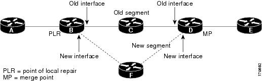
Figure 1 illustrates the FLR process.

Figure 1 Overview of RSVP FLR

Initial RSVP states are installed for an IPv4 unicast flow over Routers A, B, C, D, and E. Router A is the source or headend, while Router E is the destination or tailend. The data packets are destined to an address of Router E. Assume that a route change occurs, and the new path taken by the data packets is from Router A to Router B to Router F to Router D to Router E; therefore, the old and new paths differ on the segments between Routers B and D. The Router B to Router C to Router D segment is the old segment, while the Router B to Router F to Router D segment is the new segment.

A route may change because of a link or node failure, or if a better path becomes available.

RSVP at Router B detects that the route change affects the RSVP flow and initiates the FLR procedure. The node that initiates an FLR repair procedure, Router B in Figure 1, is the point of local repair (PLR). The node where the new and old segments meet, Router D in Figure 1, is the merge point (MP). The interfaces at the PLR and the MP that are part of the old segment are the old interfaces, while the interfaces that are part of the new segment are the new interfaces.

If a route has changed because of a failure, the PLR may not be the node that detects the failure. For example, it is possible that the link from Router C to Router D fails, and although Router C detects the failure, the route change at Router B is the trigger for the FLR procedure. Router C, in this case, is also referred to as the node that detects the failure.

Benefits of RSVP FLR

Faster Response Time to Routing Changes

FLR reduces the time that it takes for RSVP to determine that a physical link has gone down and that the data packets have been rerouted. Without FLR, RSVP may not recognize the link failure for 30 seconds when all of the sessions are impacted by having too much traffic for the available bandwidth. With FLR, this time can be significantly reduced to a few seconds.

After detecting the failure, RSVP recomputes the admission control across the new link. If the rerouted traffic fits on the new link, RSVP reserves the bandwidth and guarantees the QoS of the new traffic.

If admission control fails on the new route, RSVP does not explictly tear down the flow, but instead sends a RESVERROR message towards the receiver. If a proxy receiver is running, then RSVP sends a PATHERROR message towards the headend, in response to the RESVERROR message, indicating the admission failure. In both cases, with and without a proxy receiver, the application tears down the failed session either at the headend or at the final destination.

Until this happens, the data packets belonging to this session still flow over the rerouted segment although admission has failed and QoS is affected.

How to Configure RSVP FLR

You can configure the RSVP FLR parameters in any order that you want.

This section contains the following procedures:

Configuring the RSVP FLR Wait Time (required)

Configuring the RSVP FLR Repair Rate (required)

Configuring the RSVP FLR Notifications (required)

Verifying the RSVP FLR Configuration (optional)

Configuring the RSVP FLR Wait Time

Perform this task to configure the RSVP FLR wait time.

SUMMARY STEPS

1. enable

2. configure terminal

3. interface type number

4. ip rsvp bandwidth [interface-kbps] [single-flow-kbps]

5. ip rsvp signalling fast-local-repair wait-time interval

6. end

DETAILED STEPS

 
Command or Action
Purpose

Step 1 

enable

Example:

Router> enable

Enables privileged EXEC mode.

Enter your password if prompted.

Step 2 

configure terminal

Example:

Router# configure terminal

Enters global configuration mode.

Step 3 

interface type number

Example:

Router(config)# interface Ethernet0/0

Configures the interface type and enters interface configuration mode.

Step 4 

ip rsvp bandwidth [interface-kbps] [single-flow-kbps]

Example:

Router(config-if)# ip rsvp bandwidth 7500 7500

Enables RSVP on an interface.

The optional interface-kbps and single-flow-kbps arguments specify the amount of bandwidth that can be allocated by RSVP flows or to a single flow, respectively. Values are from 1 to 10000000.

Note Repeat this command for each interface on which you want to enable RSVP.

Step 5 

ip rsvp signalling fast-local-repair wait-time interval

Example:
Router(config-if)# ip rsvp signalling 
fast-local-repair wait-time 100

Configures the delay that RSVP uses before starting an FLR procedure.

Values for the interval argument are 0 to 5000 milliseconds (ms); the default is 0.

Step 6 

end

Example:

Router(config-if)# end

(Optional) Returns to privileged EXEC mode.


Configuring the RSVP FLR Repair Rate

Perform this task to configure the RSVP FLR repair rate.

SUMMARY STEPS

1. enable

2. configure terminal

3. ip rsvp signalling fast-local-repair rate rate

4. exit

DETAILED STEPS

 
Command or Action
Purpose

Step 1 

enable

Example:

Router> enable

Enables privileged EXEC mode.

Enter your password if prompted.

Step 2 

configure terminal

Example:

Router# configure terminal

Enters global configuration mode.

Step 3 

ip rsvp signalling fast-local-repair rate rate

Example:
Router(config)# ip rsvp signalling 
fast-local-repair rate 100

Configures the repair rate that RSVP uses for an FLR procedure.

Values for the rate argument are 1 to 2500 messages per second; the default is 400.

Note See the ip rsvp signalling fast-local-repair rate command for more information.

Step 4 

exit

Example:
Router(config)# exit

(Optional) Returns to privileged EXEC mode.

Configuring the RSVP FLR Notifications

Perform this task to configure the number of RSVP FLR notifications.

SUMMARY STEPS

1. enable

2. configure terminal

3. ip rsvp signalling fast-local-repair notifications number

4. exit

DETAILED STEPS

 
Command or Action
Purpose

Step 1 

enable

Example:

Router> enable

Enables privileged EXEC mode.

Enter your password if prompted.

Step 2 

configure terminal

Example:

Router# configure terminal

Enters global configuration mode.

Step 3 

ip rsvp signalling fast-local-repair notifications number

Example:
Router(config)# ip rsvp signalling 
fast-local-repair notifications 100

Configures the number of path state blocks (PSBs) that RSVP processes before it suspends.

Values for the number argument are 10 to 10000; the default is 1000.

Step 4 

exit

Example:
Router(config)# exit

(Optional) Returns to privileged EXEC mode.

Verifying the RSVP FLR Configuration

Perform this task to verify the configuration.


Note You can use the following show commands in user EXEC or privileged EXEC mode.


SUMMARY STEPS

1. enable

2. show ip rsvp signalling fast-local-repair [statistics [detail]]

3. show ip rsvp interface [detail] [interface-type interface-number]

4. show ip rsvp [atm-peak-rate-limit | counters | host | installed | interface | listeners | neighbor | policy | precedence | request | reservation | sbm | sender | signalling | tos]

5. show ip rsvp sender [detail] [filter [destination ip-addr | hostname] [source ip-addr | hostname] [dst-port port] [src-port port]]

6. exit

DETAILED STEPS

 
Command or Action
Purpose

Step 1 

enable

Example:

Router> enable

(Optional) Enables privileged EXEC mode.

Enter your password if prompted.

Note Skip this step if you are using the show commands in user EXEC mode.

Step 2 

show ip rsvp signalling fast-local-repair 
[statistics [detail]]
Example:
Router# show ip rsvp signalling 
fast-local-repair statistics detail

Displays FLR-specific information that RSVP maintains.

The optional statistics and detail keywords display additional information about the FLR parameters.

Step 3 

show ip rsvp interface [detail] [interface-type 
interface-number]
Example:
Router# show ip rsvp interface ethernet 1/0

Displays RSVP-related information.

The optional detail keyword displays additional information including FLR parameters.

Step 4 

show ip rsvp [atm-peak-rate-limit | counters | 
host | installed | interface | listeners | 
neighbor | policy | precedence | request | 
reservation | sbm | sender | signalling | tos]
Example:
Router# show ip rsvp

Displays specific information for RSVP categories.

Step 5 

show ip rsvp sender [detail] [filter 
[destination ip-addr | hostname] [source 
ip-addr | hostname] [dst-port port] [src-port 
port]]
Example:
Router# show ip rsvp sender detail

Displays RSVP PATH-related sender information currently in the database.

The optional detail keyword displays additional output including the FLR parameters.

Note The optional filter keyword is supported in
Cisco IOS Releases 12.0S and 12.2S only.

Step 6 

exit

Example:

Router# exit

(Optional) Exits privileged EXEC mode and returns to user EXEC mode.

Configuration Examples for RSVP FLR

This section provides configuration examples for the RSVP FLR feature.

Configuring RSVP FLR: Example

Verifying the RSVP FLR Configuration: Example

Configuring RSVP FLR: Example

The configuration options for RSVP FLR are the following:

Wait time

Number of notifications

Repair rate


Note You can configure these options in any order.


Configuring the Wait Time

The following example configures Ethernet interface 1/0 with a bandwidth of 200 kbps and a wait time of 1000 msec:

Router# configure terminal
Enter configuration commands, one per line.  End with CNTL/Z.
Router(config)# interface ethernet1/0
Router(config-if)# ip rsvp bandwidth 200
Router(config-if)# ip rsvp signalling fast-local-repair wait-time 1000

Router(config-if)# end

Configuring the Number of Notifications

The following example configures the number of flows that are repaired before suspending to 100:

Router# configure terminal
Enter configuration commands, one per line.  End with CNTL/Z.
Router(config)# ip rsvp signalling fast-local-repair notifications 100

Router(config)# end

Configuring the Repair Rate

The following example configures a repair rate of 100 messages per second:

Router# configure terminal
Enter configuration commands, one per line.  End with CNTL/Z.
Router(config)# ip rsvp signalling fast-local-repair rate 100

Router(config)# end

Verifying the RSVP FLR Configuration: Example

This section contains the following examples:

Verifying the Details for FLR Procedures

Verifying Configuration Details for a Specific Interface

Verifying Configuration Details Before, During, and After an FLR Procedure

Verifying the Details for FLR Procedures

The following example displays detailed information about FLR procedures:

Router# show ip rsvp signalling fast-local-repair statistics detail

Fast Local Repair: enabled
   Max repair rate (paths/sec): 1000
   Max processed   (paths/run): 1000

FLR Statistics:

   FLR 1: DONE
     Start Time: 15:16:32 MET Wed Oct 25 2006
     Number of PSBs repaired:          2496
     Used Repair Rate (msgs/sec):      1000
     RIB notification processing time: 91(ms)
     Time of last PSB refresh:         3111(ms)
     Time of last Resv received:       4355(ms)
     Time of last Perr received:       0(us)
     Suspend count: 2
       Run  Number   Started              Duration
       ID   of ntf.  (time from Start)
       2    498      81(ms)               10(ms)
       1    998      49(ms)               21(ms)
       0    1000     0(us)                22(ms)
     FLR Pacing Unit: 1 msec
     Affected neighbors:
       Nbr Address           Relative Delay Values (msec)
       10.1.0.70             [500   ,..., 2995  ]

Verifying Configuration Details for a Specific Interface

The following example from the show ip rsvp interface detail command displays detailed information, including FLR, for the Ethernet 1/0 interface:

Router# show ip rsvp interface detail ethernet1/0

  Et1/0:
    RSVP: Enabled
    Interface State: Up
    Bandwidth:
      Curr allocated: 9K bits/sec
      Max. allowed (total): 300K bits/sec
      Max. allowed (per flow): 300K bits/sec
      Max. allowed for LSP tunnels using sub-pools (pool 1): 0 bits/sec
      Set aside by policy (total): 0 bits/sec
    Traffic Control:
      RSVP Data Packet Classification is ON via CEF callbacks
    Signalling:
      DSCP value used in RSVP msgs: 0x30
      Number of refresh intervals to enforce blockade state: 4
    FLR Wait Time (IPv4 flows):
      Repair is delayed by 1000 msec.
    Authentication: disabled
      Key chain:   <none>
      Type:        md5
      Window size: 1
      Challenge:   disabled
    Hello Extension:
      State: Disabled

Verifying Configuration Details Before, During, and After an FLR Procedure

The following is sample output from the show ip rsvp sender detail command before an FLR procedure has occurred:

Router# show ip rsvp sender detail

PATH:
   Destination 192.168.101.21, Protocol_Id 17, Don't Police , DstPort 1
   Sender address: 10.10.10.10, port: 1
   Path refreshes:
     arriving: from PHOP 172.3.31.34 on Et0/0 every 30000 msecs
   Traffic params - Rate: 9K bits/sec, Max. burst: 9K bytes
     Min Policed Unit: 0 bytes, Max Pkt Size 2147483647 bytes
   Path ID handle: 01000401.
   Incoming policy: Accepted. Policy source(s): Default
   Status:
   Output on Ethernet1/0. Policy status: Forwarding. Handle: 02000400
     Policy source(s): Default
   Path FLR: Never repaired

The following is sample output from the show ip rsvp sender detail command at the PLR during an FLR procedure:

Router# show ip rsvp sender detail

PATH:
   Destination 192.168.101.21, Protocol_Id 17, Don't Police , DstPort 1
   Sender address: 10.10.10.10, port: 1
   Path refreshes:
     arriving: from PHOP 172.16.31.34 on Et0/0 every 30000 msecs
   Traffic params - Rate: 9K bits/sec, Max. burst: 9K bytes
     Min Policed Unit: 0 bytes, Max Pkt Size 2147483647 bytes
   Path ID handle: 01000401.
   Incoming policy: Accepted. Policy source(s): Default
   Status:
   Path FLR: PSB is currently being repaired...try later
   PLR - Old Segments: 1
    Output on Ethernet1/0, nhop 172.5.36.34
    Time before expiry: 2 refreshes
    Policy status: Forwarding. Handle: 02000400
       Policy source(s): Default

The following is sample output from the show ip rsvp sender detail command at the MP during an FLR procedure:

Router# show ip rsvp sender detail

PATH:
   Destination 192.168.101.21, Protocol_Id 17, Don't Police , DstPort 1
   Sender address: 10.10.10.10, port: 1
   Path refreshes:
     arriving: from PHOP 172.16.37.35 on Et1/0 every 30000 msecs
Traffic params - Rate: 9K bits/sec, Max. burst: 9K bytes
     Min Policed Unit: 0 bytes, Max Pkt Size 2147483647 bytes
   Path ID handle: 09000406.
   Incoming policy: Accepted. Policy source(s): Default
   Status: Proxy-terminated
   Path FLR: Never repaired
   MP - Old Segments: 1
    Input on Serial2/0, phop 172.16.36.35
    Time before expiry: 9 refreshes

The following is sample output from the show ip rsvp sender detail command at the PLR after an FLR procedure:

Router# show ip rsvp sender detail

PATH:
   Destination 192.168.101.21, Protocol_Id 17, Don't Police , DstPort 1
   Sender address: 10.10.10.10, port: 1
   Path refreshes:
     arriving: from PHOP 172.16.31.34 on Et0/0 every 30000 msecs
   Traffic params - Rate: 9K bits/sec, Max. burst: 9K bytes
     Min Policed Unit: 0 bytes, Max Pkt Size 2147483647 bytes
   Path ID handle: 05000401.
   Incoming policy: Accepted. Policy source(s): Default
   Status:
   Output on Serial3/0. Policy status: Forwarding. Handle: 3B000406
     Policy source(s): Default
   Path FLR: Started 12:56:16 EST Thu Nov 16 2006, PSB repaired 532(ms) after.

Resv/Perr: Received 992(ms) after.

Additional References

The following sections provide references related to the RSVP FLR feature.

Related Documents

Related Topic
Document Title

RSVP commands: complete command syntax, command mode, defaults, usage guidelines, and examples

Cisco IOS Quality of Service Solutions Command Reference, Release 12.2SR

QoS features including signaling, classification, and congestion management

Cisco IOS Quality of Service Solutions Configuration Guide, Release 12.4


Standards

Standard
Title

No new or modified standards are supported by this feature, and support for existing standards has not been modified by this feature.


MIBs

MIB
MIBs Link

No new or modified MIBs are supported by this feature, and support for existing MIBs has not been modified by this feature.

To locate and download MIBs for selected platforms, Cisco IOS releases, and feature sets, use Cisco MIB Locator found at the following URL:

http://www.cisco.com/go/mibs


RFCs

RFC
Title

RFC 2205

Resource ReSerVation Protocol (RSVP)—Version 1 Functional Specification

RFC 2209

Resource ReSerVation Protocol (RSVP)—Version 1 Messaging Processing Rules


Technical Assistance

Description
Link

The Cisco Support website provides extensive online resources, including documentation and tools for troubleshooting and resolving technical issues with Cisco products and technologies. Access to most tools on the Cisco Support website requires a Cisco.com user ID and password. If you have a valid service contract but do not have a user ID or password, you can register on Cisco.com.

http://www.cisco.com/techsupport


Command Reference

This section documents only commands that are new or modified.

New Commands

clear ip rsvp signalling fast-local-repair statistics

ip rsvp signalling fast-local-repair notifications

ip rsvp signalling fast-local-repair rate

ip rsvp signalling fast-local-repair wait-time

show ip rsvp signalling fast-local-repair

Modified Commands

show ip rsvp

show ip rsvp interface

show ip rsvp sender

clear ip rsvp signalling fast-local-repair statistics

To clear (set to zero) the Resource Reservation Protocol (RSVP) fast local repair (FLR) counters, use the clear ip rsvp signalling fast-local-repair statistics command in user EXEC or privileged EXEC mode.

clear ip rsvp signalling fast-local-repair statistics

Syntax Description

This command has no keywords or arguments.

Command Default

The default is to clear all the RSVP FLR counters.

Command Modes

User EXEC
Privileged EXEC

Command History

Release
Modification

12.2(33)SRB

This command was introduced.


Usage Guidelines

Use the clear ip rsvp signalling fast-local-repair statistics command to set all the RSVP FLR counters to zero. The statistics include information about FLR procedures such as the current state, the start time, and the repair rate.

Examples

The following example clears all the RSVP FLR counters being maintained in the database:

Router# clear ip rsvp signalling fast-local-repair statistics

Related Commands

Command
Description

show ip rsvp signalling fast-local-repair

Displays FLR-related information.


ip rsvp signalling fast-local-repair notifications

To configure the number of per flow notifications that Resource Reservation Protocol (RSVP) processes during a fast local repair (FLR) procedure before suspending, use the ip rsvp signalling fast-local-repair notifications command in global configuration mode. To set the number of notifications to its default, use the no form of this command.

ip rsvp signalling fast-local-repair notifications number

no ip rsvp signalling fast-local-repair notifications

Syntax Description

number

Total number of notifications to be sent. The range is 10 to 10000. The default is 1000.


Command Default

There are always notifications sent by the routing information base (RIB) and processed by RSVP. If this command is not configured, RSVP processes 1000 notifications, suspends, then resumes processing of another 1000 notifications, and so on.

Command Modes

Global configuration

Command History

Release
Modification

12.2(33)SRB

This command was introduced.


Usage Guidelines

Upon a route change, RIB builds a list of notifications, one per affected flow, and notifies RSVP by sending an event including these notifications. Therefore, these events can contain thousands of elements depending on the number of path state blocks (PSBs) affected.

RSVP processes, by default, 1000 notifications at a time and then suspends if required, to prevent the CPU from being overwhelmed. However, you can configure this number using the ip rsvp signalling fast-local-repair notifications command.

Examples

The following example configures the number of flows that are repaired before RSVP suspends to 100:

Router(config)# ip rsvp signalling fast-local-repair notifications 100

Related Commands

Command
Description

ip rsvp signalling fast-local-repair rate

Configures the repair rate that RSVP uses for an FLR procedure.

ip rsvp signalling fast-local-repair wait-time

Configures the delay that RSVP uses to start an FLR procedure.

show ip rsvp signalling fast-local-repair

Displays FLR-specific information maintained by RSVP.


ip rsvp signalling fast-local-repair rate

To configure the repair rate that Resource Reservation Protocol (RSVP) uses for a fast local repair (FLR) procedure, use the ip rsvp signalling fast-local-repair rate command in global configuration mode. To set the repair rate to its default, use the no form of this command.

ip rsvp signalling fast-local-repair rate rate

no ip rsvp signalling fast-local-repair rate

Syntax Description

rate

FLR rate for PATH state refresh and repair, in messages per second (msg/sec). The range is 0 to 5000. The default is 400.


Command Default

If this command is not configured, the RSVP message pacing rate is used.


Note The RSVP message pacing rate is enabled by default in Cisco IOS Release 12.2 and later.


Command Modes

Global configuration

Command History

Release
Modification

12.2(33)SRB

This command was introduced.


Usage Guidelines

The default repair rate is based on the RSVP message pacing rate.

If you configure the FLR rate by using the ip rsvp signalling fast-local-repair rate command, and RSVP message pacing is enabled, the minimum between the FLR rate and the RSVP message pacing rate takes effect. If you disable the RSVP rate limit by using the no ip rsvp signalling rate-limit command, then the FLR rate is used. However, if you disable the RSVP rate limit and do not configure an FLR rate, then RSVP performs no message pacing and messages are sent back-to-back. This action is not recommended because the point of local repair (PLR) may flood the downstream node with PATH messages causing some of them to be dropped.

The repair rate is determined at notification time, and this same rate is used during the time of the repair even if you change either the RSVP message pacing rate or the FLR rate during this time.

Examples

The following example configures a repair rate of 100 messages per second:

Router(config)# ip rsvp signalling fast-local-repair rate 100

Related Commands

Command
Description

ip rsvp signalling fast-local-repair notifications

Configures the number of notifications that are processed before RSVP suspends.

ip rsvp signalling fast-local-repair wait-time

Configures the delay used to start an FLR procedure.

ip rsvp signalling rate-limit

Controls the transmission rate for RSVP messages sent to a neighboring router during a specified amount of time.


ip rsvp signalling fast-local-repair wait-time

To configure the delay that Resource Reservation Protocol (RSVP) uses before starting a fast local repair (FLR) procedure, use the ip rsvp signalling fast-local-repair wait-time command in interface configuration mode. To set the delay to its default, use the no form of this command.

ip rsvp signalling fast-local-repair wait-time interval

no ip rsvp signalling fast-local-repair wait-time

Syntax Description

interval

Amount of time before an FLR procedure begins, in milliseconds (ms). The range is 0 to 5000 ms. The default is 0.


Command Default

This command is disabled by default; therefore, no delay is configured.

Command Modes

Interface configuration

Command History

Release
Modification

12.2(33)SRB

This command was introduced.


Usage Guidelines

Use the ip rsvp signalling fast-local-repair wait-time command to configure the delay desired in starting an FLR procedure. If you do not configure a delay, then path refreshes are triggered immediately after RSVP receives a route change notification from the routing information base (RIB).

Examples

The following example configures a delay of 100 ms:

Router(config-if)# ip rsvp signalling fast-local-repair wait-time 100

Related Commands

Command
Description

ip rsvp signalling fast-local-repair notifications

Configures the number of notifications that are processed before RSVP suspends.

ip rsvp signalling fast-local-repair rate

Configures the repair rate that RSVP uses for an FLR procedure.


show ip rsvp

To display specific information for Resource Reservation Protocol (RSVP) categories, use the show ip rsvp command in user EXEC or privileged EXEC mode.

show ip rsvp [atm-peak-rate-limit | counters | host | installed | interface | listeners | neighbor | policy | precedence | request | reservation | sbm | sender | signalling | tos]

Syntax Description

atm-peak-rate-limit

(Optional) RSVP peak rate limit.

counters

(Optional) RSVP statistics.

host

(Optional) RSVP endpoint senders and receivers.

installed

(Optional) RSVP installed reservations.

interface

(Optional) RSVP interface information.

listeners

(Optional) RSVP listeners.

neighbor

(Optional) RSVP neighbor information.

policy

(Optional) RSVP policy information.

precedence

(Optional) RSVP precedence settings.

request

(Optional) RSVP reservations from upstream.

reservation

(Optional) RSVP reservation requests from downstream.

sbm

(Optional) RSVP subnet bandwidth manager (SBM) information.

sender

(Optional) RSVP path state information.

signalling

(Optional) RSVP signaling information.

tos

(Optional) RSVP type of service (TOS) settings.


Command Modes

User EXEC
Privileged EXEC

Command History

Release
Modification

12.0(3)T

This command was introduced.

12.2(13)T

The listeners and policy keywords were added, and this command was modified to display RSVP global settings when no keywords or arguments are entered.

12.2(33)SRB

The command output was modified to display fast local repair (FLR) information.


Examples

The following example includes FLR information:

Router# show ip rsvp

RSVP: enabled (on 4 interface(s))

Signalling:
   Refresh interval (msec): 30000
   Refresh misses: 4

Rate Limiting: enabled
   Burst: 8
   Limit: 37
   Maxsize: 2000
   Period (msec): 20
   Max rate (msgs/sec): 400

Refresh Reduction: disabled
   ACK delay (msec): 250
   Initial retransmit delay (msec): 1000
   Local epoch: 0x7C11BE
   Message IDs: in use 0, total allocated 0, total freed 0

Neighbors: 2
   Raw IP encap: 2  UDP encap: 0  Raw IP, UDP encap: 0

Hello:
   Fast-Reroute/Reroute: Disabled
     Statistics: Disabled
   Graceful Restart: Disabled

Graceful Restart: Disabled
   Refresh interval: 10000 msecs
   Refresh misses: 4
   DSCP: 0x30
   Advertised restart time: 5 msecs
   Advertised recovery time: 0 msecs
   Maximum wait for recovery: 3600000 msecs

Fast-Reroute:
   PSBs w/ Local protection desired
     Yes: 0
     No:  0

Fast Local Repair: enabled
   Max repair rate (paths/sec): 400
   Max processed   (paths/run): 1000

Local policy:
COPS:

Generic policy settings:
     Default policy: Accept all
     Preemption:     Disabled

Table 1 describes the significant fields shown in the display.

Table 1 show ip rsvp Field Descriptions 

Field
Description

RSVP: enabled or disabled

The state of RSVP.

Note This field is disabled only if an internal error occurred when registering with RIB.

Signalling

The RSVP signaling parameters in effect are as follows:

Refresh interval—Time, in milliseconds (ms), between sending refreshes for each RSVP state.

Refresh misses—Number of successive refresh messages that can be missed before RSVP considers the state expired and tears it down.

Rate Limiting: enabled or disabled

The RSVP rate-limiting parameters in effect are as follows:

Burst—Maximum number of RSVP messages allowed to be sent to a neighboring router during an interval.

Limit—Maximum number of RSVP messages to send per queue interval.

Maxsize—Maximum size of the message queue, in bytes.

Period—Length of an interval (timeframe), in milliseconds (msec).

Max rate—Maximum number of messages allowed to be sent per second.

Refresh Reduction: enabled or disabled

The RSVP refresh-reduction parameters in effect are as follows:

ACK delay (msec)—How long, in milliseconds, before the receiving router sends an acknowledgment (ACK).

Initial retransmit delay (msec)—How long, in milliseconds, before the router retransmits a message.

Local epoch—The RSVP message identifier (ID); randomly generated each time a node reboots or the RSVP process restarts.

Message IDs—The number of message IDs in use, the total number allocated, and the total number available (freed).

Neighbors

The total number of neighbors and the types of encapsulation in use including RSVP and User Datagram Protocol (UDP).

Hello

Subsequent fields describe the processes for which hello is enabled or disabled. Choices are Fast Reroute, reroute (hello for state timer), and Graceful restart for a node with restart capability.

Statistics

Status of hello statistics. Valid values are as follows:

Enabled—Statistics are configured. Hello packets are time-stamped when they arrive in the hello input queue for the purpose of recording the time it takes until they are processed.

Disabled—Hello statistics are not configured.

Shutdown—Hello statistics are configured, but not operational. The input queue is too long (that is, more than 10,000 packets are queued).

Graceful Restart: enabled or disabled

The RSVP Graceful Restart parameters in effect are as follows:

Refresh interval—Frequency, in milliseconds (msecs), with which a node sends a hello message to its neighbor.

Refresh misses—Number of missed hello messages that trigger a neighbor-down event upon which stateful switchover (SSO) procedures are started.

DSCP—Differentiated services code point (DSCP) value in the IP header of a hello message.

Advertised restart time—Time, in milliseconds (msecs), required for the sender to restart the RSVP-Traffic Engineering (TE) component and exchange hello messages after a failure.

Advertised recovery time—Time, in milliseconds (msecs), within which a recovering node wants its neighbor router to resynchronize the RSVP or Multiprotocol Label Switching (MPLS) forwarding state after SSO. A zero value indicates that the RSVP or MPLS forwarding state is not preserved after SSO.

Maximum wait for recovery—Maximum amount of time, in milliseconds (msecs), that a router waits for a neighbor to recover.

Fast-Reroute

The Fast Reroute parameters in effect are as follows:

PSBs w/ Local protection desired—Yes means that path state blocks (PSBs) are rerouted when a tunnel goes down and packet flow is not interrupted; No means that PSBs are not rerouted.

Fast Local Repair: enabled or disabled

The Fast Local Repair parameters in effect are as follows:

Max repair rate (paths/sec)—Maximum repair rate, in paths per second.

Max processed (paths/run)—Maximum notification elements processed, in paths per run.

Local policy

The local policy currently configured.

COPS

The Common Open Policy Service (COPS) currently in effect.

Generic policy settings

Policy settings that are not specific to COPS or the local policy.

Default policy: Accept all means that all RSVP messages are accepted and forwarded. Reject all means all RSVP messages are rejected.

Preemption: Disabled means that RSVP is not prioritizing reservations and allocating bandwidth accordingly. Enabled means that RSVP is prioritizing reservations and allocating more bandwidth to those with the highest priority.


Related Commands

Command
Description

debug ip rsvp

Displays debug messages for RSVP categories.


show ip rsvp interface

To display Resource Reservation Protocol (RSVP)-related information, use the show ip rsvp interface command in user EXEC or privileged EXEC mode.

show ip rsvp interface [interface-type interface-number] [detail]

Syntax Description

interface-type

(Optional) Type of the interface.

interface-number

(Optional) Number of the interface.

detail

(Optional) Displays additional information about interfaces.


Command Modes

User EXEC
Privileged EXEC

Command History

Release
Modification

11.2

This command was introduced.

12.2(2)T

The optional detail keyword was added.

12.2(4)T

This command was implemented on the Cisco 7500 series and the ATM permanent virtual circuit (PVC) interface.

12.0(22)S

The command output was modified to display hello message information.

12.2(14)S

This command was integrated into Cisco IOS Release 12.2(14)S.

12.2(13)T

The following modifications were made to this command:

Rate-limiting and refresh-reduction information was added to the output display.

RSVP global settings display when no keywords or arguments are entered.

12.2(15)T

The following modifications were made to this command:

The effects of compression on admission control and the RSVP bandwidth limit counter were added to the display.

Cryptographic authentication parameters were added to the display.

12.2(18)SFX2

This command was integrated into Cisco IOS Release 12.2(18)SFX2.

12.2(28)SB

This command was integrated into Cisco IOS Release 12.2(28)SB.

12.2(33)SRA

This command was integrated into Cisco IOS Release 12.2(33)SRA.

12.2(33)SRB

The command output was modified to display fast local repair (FLR) information.


Usage Guidelines

Use the show ip rsvp interface command to display information about interfaces on which RSVP is enabled, including the current allocation budget and maximum available bandwidth. Enter the optional detail keyword for additional information, including bandwidth and signaling parameters and blockade state.

Use the show ip rsvp interface detail command to display information about the RSVP parameters associated with an interface. These parameters include the following:

Total RSVP bandwidth

RSVP bandwidth allocated to existing flows

Maximum RSVP bandwidth that can be allocated to a single flow

The type of admission control supported (header compression methods)

The compression methods supported by RSVP compression prediction

Examples

The following command shows information for each interface on which RSVP is enabled:

Router# show ip rsvp interface

interface    allocated  i/f max  flow max sub max 
PO0/0        0          200M     200M     0   
PO1/0        0          50M      50M      0   
PO1/1        0          50M      50M      0   
PO1/2        0          50M      50M      0   
PO1/3        0          50M      50M      0   
Lo0          0          200M     200M     0   

Table 2 describes the fields shown in the display.

Table 2 show ip rsvp interface Field Descriptions 

Field
Description

interface

Interface name.

allocated

Current allocation budget.

i/f max

Maximum allocatable bandwidth.

flow max

Largest single flow allocatable on this interface.

sub max

Largest subpool value allowed on this interface.


Detailed RSVP Information Example

The following command shows detailed RSVP information for each interface on which RSVP is enabled:

Router# show ip rsvp interface detail

PO0/0:
   Bandwidth:
     Curr allocated:0 bits/sec
     Max. allowed (total):200M bits/sec
     Max. allowed (per flow):200M bits/sec
     Max. allowed for LSP tunnels using sub-pools:0 bits/sec
     Set aside by policy (total):0 bits/sec
   Signalling:
     DSCP value used in RSVP msgs:0x3F
     Number of refresh intervals to enforce blockade state:4
     Number of missed refresh messages:4
     Refresh interval:30

 PO1/0:
   Bandwidth:
     Curr allocated:0 bits/sec
     Max. allowed (total):50M bits/sec
     Max. allowed (per flow):50M bits/sec
     Max. allowed for LSP tunnels using sub-pools:0 bits/sec
     Set aside by policy (total):0 bits/sec
   Signalling:
     DSCP value used in RSVP msgs:0x3F
     Number of refresh intervals to enforce blockade state:4
     Number of missed refresh messages:4
     Refresh interval:30

PO1/1:
   Bandwidth:
     Curr allocated:0 bits/sec
     Max. allowed (total):50M bits/sec
     Max. allowed (per flow):50M bits/sec
     Max. allowed for LSP tunnels using sub-pools:0 bits/sec
     Set aside by policy (total):0 bits/sec
   Signalling:
     DSCP value used in RSVP msgs:0x3F
     Number of refresh intervals to enforce blockade state:4
     Number of missed refresh messages:4
     Refresh interval:30

 PO1/2:
   Bandwidth:
     Curr allocated:0 bits/sec
     Max. allowed (total):50M bits/sec
     Max. allowed (per flow):50M bits/secMax. allowed for LSP tunnels using sub-pools:0 
bits/sec
     Set aside by policy (total):0 bits/sec
   Signalling:
     DSCP value used in RSVP msgs:0x3F
     Number of refresh intervals to enforce blockade state:4
     Number of missed refresh messages:4
     Refresh interval:30

 PO1/3:
   Bandwidth:
     Curr allocated:0 bits/sec
     Max. allowed (total):50M bits/sec
     Max. allowed (per flow):50M bits/sec
     Max. allowed for LSP tunnels using sub-pools:0 bits/sec
     Set aside by policy (total):0 bits/sec
   Signalling:
     DSCP value used in RSVP msgs:0x3F
     Number of refresh intervals to enforce blockade state:4
     Number of missed refresh messages:4
     Refresh interval:30

 Lo0:
   Bandwidth:
     Curr allocated:0 bits/sec
     Max. allowed (total):200M bits/sec
     Max. allowed (per flow):200M bits/sec
     Max. allowed for LSP tunnels using sub-pools:0 bits/sec
     Set aside by policy (total):0 bits/sec
   Signalling:
     DSCP value used in RSVP msgs:0x3F
     Number of refresh intervals to enforce blockade state:4
     Number of missed refresh messages:4
     Refresh interval:30

Table 3 describes the significant fields shown in the detailed display for interface PO0/0. The fields for the other interfaces are similar.

Table 3 show ip rsvp interface detail Field Descriptions—Detailed RSVP Information Example

Field
Description

PO0/0

Interface name.

Bandwidth

The RSVP bandwidth parameters in effect are as follows:

Curr allocated—Amount of bandwidth currently allocated, in bits per second.

Max. allowed (total)—Maximum amount of bandwidth allowed, in bits per second.

Max. allowed (per flow)—Maximum amount of bandwidth allowed per flow, in bits per second.

Max. allowed for LSP tunnels using sub-pools—Maximum amount of bandwidth allowed for label switched path (LSP) tunnels, in bits per second.

Set aside by policy (total)—The amount of bandwidth set aside by the local policy, in bits per second.

Signalling

The RSVP signalling parameters in effect are as follows:

DSCP value used in RSVP msgs—Differentiated services code point (DSCP) used in RSVP messages.

Number of refresh intervals to enforce blockade state—How long, in milliseconds, before the blockade takes effect.

Number of missed refresh messages—How many refresh messages until the router state expires.

Refresh interval—How long, in milliseconds, until a refresh message is sent.


RSVP Compression Method Prediction Example

The following example from the show ip rsvp interface detail command shows the RSVP compression method prediction configuration for each interface on which RSVP is configured:

Router# show ip rsvp interface detail

 Et2/1:
   Bandwidth:
     Curr allocated:0 bits/sec
     Max. allowed (total):1158K bits/sec
     Max. allowed (per flow):128K bits/sec
     Max. allowed for LSP tunnels using sub-pools:0 bits/sec
     Set aside by policy (total):0 bits/sec
   Admission Control:
     Header Compression methods supported:
       rtp (36 bytes-saved), udp (20 bytes-saved)
   Neighbors:
     Using IP encap:0.  Using UDP encap:0
   Signalling:
     Refresh reduction:disabled
   Authentication:disabled 

 Se3/0:
   Bandwidth:
     Curr allocated:0 bits/sec
     Max. allowed (total):1158K bits/sec
     Max. allowed (per flow):128K bits/sec
     Max. allowed for LSP tunnels using sub-pools:0 bits/sec
     Set aside by policy (total):0 bits/sec
   Admission Control:
     Header Compression methods supported:
       rtp (36 bytes-saved), udp (20 bytes-saved)
   Neighbors:
     Using IP encap:1.  Using UDP encap:0
   Signalling:
     Refresh reduction:disabled
   Authentication:disabled 

Table 4 describes the significant fields shown in the display for Ethernet interface 2/1. The fields for serial interface 3/0 are similar.

Table 4 show ip rsvp interface detail Field Descriptions—RSVP Compression Method Prediction Example

Field
Description

Et2/1

Interface name and number.

Bandwidth

The RSVP bandwidth parameters in effect are as follows:

Curr allocated—Amount of bandwidth currently allocated, in bits per second.

Max. allowed (total)—Maximum amount of bandwidth allowed, in bits per second.

Max. allowed (per flow)—Maximum amount of bandwidth allowed per flow, in bits per second.

Max. allowed for LSP tunnels using sub-pools—Maximum amount of bandwidth allowed for LSP tunnels, in bits per second.

Set aside by policy (total)—The amount of bandwidth set aside by the local policy, in bits per second.

Admission Control

The type of admission control in effect is as follows:

Header Compression methods supported:

Real-Time Transport Protocol (RTP) or User Data Protocol (UDP) compression schemes and the number of bytes saved per packet.

Neighbors

The number of neighbors using IP and UDP encapsulation.

Signalling

The type of signaling in effect; Refresh reduction is either enabled (active) or disabled (inactive).

Authentication

Authentication is either enabled (active) or disabled (inactive).


Cryptographic Authentication Example

The following example from the show ip rsvp interface detail command displays detailed information, including the cryptographic authentication parameters, for all RSVP-configured interfaces on the router:

Router# show ip rsvp interface detail

 Et0/0:
   Bandwidth:
    Curr allocated: 0 bits/sec
    Max. allowed (total): 7500K bits/sec
    Max. allowed (per flow): 7500K bits/sec
    Max. allowed for LSP tunnels using sub-pools: 0 bits/sec
    Set aside by policy (total):0 bits/sec
   Neighbors:
    Using IP encap: 0.  Using UDP encap: 0
   Signalling:
    Refresh reduction: disabled
   Authentication: enabled
    Key:           11223344
    Type:          sha-1
    Window size:   2
    Challenge:     enabled

Table 5 describes the significant fields shown in the display.

Table 5 show ip rsvp interface detail Field Descriptions—Cryptograhic
Authentication Example 

Field
Description

Et0/0

Interface name and number.

Bandwidth

The RSVP bandwidth parameters in effect are as follows:

Curr allocated—Amount of bandwidth currently allocated, in bits per second.

Max. allowed (total)—Maximum amount of bandwidth allowed, in bits per second.

Max. allowed (per flow)—Maximum amount of bandwidth allowed per flow, in bits per second.

Max. allowed for LSP tunnels using sub-pools—Maximum amount of bandwidth allowed for LSP tunnels, in bits per second.

Set aside by policy (total)—The amount of bandwidth set aside by the local policy, in bits per second.

Neighbors

The number of neighbors using IP and UDP encapsulation.

Signalling

The type of signaling in effect; Refresh reduction is either enabled (active) or disabled (inactive).

Authentication

Authentication is either enabled (active) or disabled (inactive). The parameters are as follows:

Key—The key (string) for the RSVP authentication algorithm displayed in clear text (for example, 11223344) or encrypted <encrypted>.

Type—The algorithm to generate cryptographic signatures in RSVP messages; possible values are md5 and sha-1.

Window size—Maximum number of RSVP authenticated messages that can be received out of order.

Challenge—The challenge-response handshake performed with any new RSVP neighbors that are discovered on a network; possible values are enabled (active) or disabled (inactive).


RSVP FLR Example

The following example from the show ip rsvp interface detail command displays detailed information, including FLR, for Ethernet interface 1/0:

Router# show ip rsvp interface detail ethernet 1/0

  Et1/0:
    RSVP: Enabled
    Interface State: Up
    Bandwidth:
      Curr allocated: 9K bits/sec
      Max. allowed (total): 300K bits/sec
      Max. allowed (per flow): 300K bits/sec
      Max. allowed for LSP tunnels using sub-pools (pool 1): 0 bits/sec
      Set aside by policy (total): 0 bits/sec
    Traffic Control:
      RSVP Data Packet Classification is ON via CEF callbacks
    Signalling:
      DSCP value used in RSVP msgs: 0x30
      Number of refresh intervals to enforce blockade state: 4
    FLR Wait Time (IPv4 flows):
      Repair is delayed by 500 msec.
    Authentication: disabled
      Key chain:   <none>
      Type:        md5
      Window size: 1
      Challenge:   disabled
    Hello Extension:
      State: Disabled

Table 6 describes the significant fields shown in the display.

Table 6 show ip rsvp interface detail Field Descriptions—FLR Example 

Field
Description

Et1/0

Interface name and number.

RSVP

Enabled means active; disabled means inactive.

Interface State

Up means that the interface is configured; down means that the interface is not configured.

Bandwidth

The RSVP bandwidth parameters in effect are as follows:

Curr allocated—Amount of bandwidth currently allocated, in bits per second.

Max. allowed (total)—Maximum amount of bandwidth allowed, in bits per second.

Max. allowed (per flow)—Maximum amount of bandwidth allowed per flow, in bits per second.

Max. allowed for LSP tunnels using sub-pools—Maximum amount of bandwidth allowed for LSP tunnels, in bits per second.

Set aside by policy (total)—The amount of bandwidth set aside by the local policy, in bits per second.

Traffic Control

RSVP Data Packet Classification is ON via CEF callbacks means that RSVP is not processing every packet; therefore, excess overhead is avoided and network performance is improved.

Signalling

The signaling parameters in effect are as follows:

DSCP value used in RSVP msgs—Differentiated services code point (DSCP) value used in RSVP messages.

Number of refresh intervals to enforce blockade state—How long, in milliseconds, before the blockade takes effect.

FLR Wait Time (IPv4 flows)

Repair is delayed by 500 msec represents the amount of time, in milliseconds, before the FLR procedure begins on the specified interface.

Authentication

Authentication is either enabled (active) or disabled (inactive). The parameters are as follows:

Key—The key (string) for the RSVP authentication algorithm displayed in clear text (for example, 11223344) or encrypted <encrypted>.

Type—The algorithm to generate cryptographic signatures in RSVP messages; possible values are md5 and sha-1.

Window size—Maximum number of RSVP authenticated messages that can be received out of order.

Challenge—The challenge-response handshake performed with any new RSVP neighbors that are discovered on a network; possible values are enabled (active) or disabled (inactive).

Hello Extension

Enables RSVP nodes to detect when a neighboring node is not reachable. The state is either enabled (active) or disabled (inactive).


Related Commands

Command
Description

show ip rsvp installed

Displays RSVP-related installed filters and corresponding bandwidth information.

show ip rsvp neighbor

Displays current RSVP neighbors.


show ip rsvp sender

To display Resource Reservation Protocol (RSVP) PATH-related sender information currently in the database, use the show ip rsvp sender command in user EXEC or privileged EXEC mode.

Syntax for T Releases

show ip rsvp sender [ip-address | hostname] [detail]

Syntax for 12.0S and 12.2S Releases

show ip rsvp sender [detail] [filter [destination ip-address | hostname] [dst-port port-number] [source ip-address | hostname] [src-port port-number]]

Syntax Description

ip-address

(Optional) Destination IP address.

hostname

(Optional) Hostname.

detail

(Optional) Specifies additional sender information.

filter

(Optional) Specifies a subset of the senders to display.

destination ip-address

(Optional) Destination IP address of the sender.

hostname

(Optional) Hostname of the sender.

dst-port port-number

(Optional) Destination port number. The range is from 0 to 65535.

source ip-address

(Optional) Source IP address of the sender.

hostname

(Optional) Hostname of the sender.

src-port port-number

(Optional) Source port number. The range is from 0 to 65535.


Command Modes

User EXEC
Privileged EXEC

Command History

Release
Modification

11.2

This command was introduced.

12.0(22)S

The command output was modified to display Fast Reroute information, and support was introduced for the Cisco 10000 series Edge Services Router (ESR).

12.2(18)SXD1

This command was integrated into Cisco IOS Release 12.2(18)SXD1.

12.4(4)T

The command output was modified to display application ID information.

12.2(33)SRA

This command was integrated into Cisco IOS Release 12.2(33)SRA.

12.2(31)SB2

This command was integrated into Cisco IOS Release 12.2(31)SB2.

12.2(33)SRB

The command output was modified to display fast local repair (FLR) information.


Usage Guidelines

Use the show ip rsvp sender command to display the RSVP sender (PATH) information currently in the database for a specified interface or for all interfaces.

The show ip rsvp sender command is very useful for determining the state of RSVP signaling both before and after a label-switched packet (LSP) has been fast rerouted. The show ip rsvp sender command is especially useful when used at the point of local repair (PLR) or at the merge point (MP).

Limiting the Display

When hundreds or thousands of tunnels exist and you are interested in only a few, you can display output for only a single tunnel or a subset of tunnels. To request a limited display, enter the show ip rsvp sender command with the appropriate keyword (called an output filter): destination, dst-port, source, and src-port. You can enter any or all of the output filters, and you can enter them whether or not you specify the detail keyword.

Fast Local Repair (FLR) Statistics

Use the show ip rsvp sender detail command to display FLR statistics before, during, and after an FLR procedure. This command shows when a path state block (PSB) was repaired and can be used to determine when the cleanup began after the FLR procedure has finished. However, this command does not display old PLR or MP segments.

Examples

show ip rsvp sender Example

The following is sample output from the show ip rsvp sender command:

Router# show ip rsvp sender

To              From            Pro DPort Sport Prev Hop        I/F
172.16.1.49     172.16.4.53     1   0     0     172.16.3.53     Et1
172.16.2.51     172.16.5.54     1   0     0     172.16.3.54     Et1

Table 7 describes the significant fields shown in the display.

Table 7 show ip rsvp sender Field Descriptions 

Field
Description

To

IP address of the receiver.

From

IP address of the sender.

Pro

Protocol code. Code 1 indicates an IP protocol such as TCP or UDP.

DPort

Destination port number.

Sport

Source port number.

Prev Hop

IP address of the previous hop.

I/F

Interface of the previous hop.


show ip rsvp sender detail with Application ID Example

The following is sample output from the show ip rsvp sender detail command with application IDs configured:

Router# show ip rsvp sender detail

PATH Session address: 192.168.104.3, port: 4444. Protocol: UDP
  Sender address: 192.168.104.1, port: 4444
     Inbound from: 192.168.104.1 on interface: 
  Traffic params - Rate: 5K bits/sec, Max. burst: 1K bytes
                   Min Policed Unit: 0 bytes, Max Pkt Size 4294967295 bytes
  Path ID handle: 09000408.
  Incoming policy: Accepted. Policy source(s): Default
    Priorities - preempt: 5, defend: 2
    Application ID: 'GUID=www.cisco.com, VER=10.1.1.2, APP=voice, SAPP=h323'
                    '/usr/local/bin/CallManager'
  Status: Proxied
  Output on ATM1/0.1. Policy status: Forwarding. Handle: 04000409
    Policy source(s): Default

Table 8 describes the significant fields shown in the display.

Table 8 show ip rsvp sender detail Field Descriptions 

Field
Descriptions

PATH Session address

Destination IP address of the PATH message.

port—Number of the destination port.

Protocol—IP protocol used.

Sender address

Source IP address of the PATH message.

port—Number of the source port.

Inbound from

IP address of the sender and the interface name.

Note A blank interface field means that the PATH message originated at the router on which the show command is being executed (the headend router). A specified interface means that the PATH message originated at an upstream router.

Traffic params

Traffic parameters in effect:

Rate—Speed, in kilobits per second.

Max. burst—Largest amount of data allowed, in kilobytes.

Min Policed Unit—Size, in bytes, of the smallest packet generated by the application, including the application data and all protocol headers at or above the IP level.

Max Pkt Size—Largest packet allowed in bytes.

PATH ID handle

Internal database ID assigned to the PATH message by RSVP for bookkeeping purposes.

Incoming policy

State of the incoming policy:

Accepted—RSVP PATH messages are being accepted, but not forwarded.

Not Accepted—RSVP PATH messages are being rejected.

Policy source(s)—Type of policy in effect. Values are the following:

default.

local.

Multiprotocol Label Switching (MPLS)/Traffic Engineering (TE).

Priorities

Preemption priorities in effect:

preempt—The startup priority; values are 0 to 7 for traffic engineering (TE) reservations with 0 being the highest. Values are 0 to 65535 for non-TE reservations with 0 being the lowest.

defend—The hold priority; values are the same as for preempt.

Application ID

A quotable string that identifies the sender application and can be used to match on local policies. The string includes the policy locator in the X.500 Distinguished Name format and the application or filename of the sender application.

Status

Status of the local policy:

Proxied—Head.

Proxy-terminated—Tail.

Blockaded—Tail or midpoint and an RESVERROR message has recently been received; therefore, the PSB enters the blockaded state.

Output on interface

Policy status (on the outbound interface):

Forwarding—Inbound PATH messages are being forwarded.

Not Forwarding—Outbound PATH messages are being rejected.

Handle—Internal database ID assigned to the PATH message by RSVP for bookkeeping purposes.

Policy source(s)

Type of local (outbound) policy in effect:

default.

local.

MPLS/TE.


show ip rsvp sender detail Before FLR Example

The following is sample output from the show ip rsvp sender detail command before FLR has occurred:

Router# show ip rsvp sender detail

PATH:
   Destination 192.168.101.21, Protocol_Id 17, Don't Police , DstPort 1
   Sender address: 10.10.10.10, port: 1
   Path refreshes:
     arriving: from PHOP 172.16.31.34 on Et0/0 every 30000 msecs
   Traffic params - Rate: 9K bits/sec, Max. burst: 9K bytes
     Min Policed Unit: 0 bytes, Max Pkt Size 2147483647 bytes
   Path ID handle: 01000401.
   Incoming policy: Accepted. Policy source(s): Default
   Status:
   Output on Ethernet1/0. Policy status: Forwarding. Handle: 02000400
     Policy source(s): Default
   Path FLR: Never repaired

Table 9 describes the significant fields shown in the display.

Table 9 show ip rsvp sender detail Field Descriptions—Before FLR 

Field
Descriptions

PATH

PATH message information:

Destination IP address.

Protocol ID number.

Policing.

Destination port number.

Sender address

Source IP address of the PATH message.

port—Number of the source port.

Path refreshes

Refresh information:

IP address of the source (previous hop [PHOP]).

Interface name and number.

Frequency, in milliseconds (msec).

Traffic params

Traffic parameters in effect:

Rate—Speed, in kilobits per second.

Max. burst—Largest amount of data allowed, in kilobytes.

Min Policed Unit—Size, in bytes, of the smallest packet generated by the application, including the application data and all protocol headers at or above the IP level.

Max Pkt Size—Largest packet allowed, in bytes.

PATH ID handle

Internal database ID assigned to the PATH message by RSVP for bookkeeping purposes.

Incoming policy

State of the incoming policy:

Accepted—RSVP PATH messages are being accepted, but not forwarded.

Not Accepted—RSVP PATH messages are being rejected.

Policy source(s)—Type of policy in effect. Values are the following:

default.

local.

Multiprotocol Label Switching (MPLS)/Traffic Engineering (TE).

Status

Status of the local policy:

Proxied—Head.

Proxy-terminated—Tail.

Blockaded—Tail or midpoint and an RESVERROR message has recently been received; therefore, the PSB enters the blockaded state.

Note A blank field means none of the above.

Output on interface

Policy status (on the outbound interface):

Forwarding—Inbound PATH messages are being forwarded.

Not Forwarding—Outbound PATH messages are being rejected.

Handle—Internal database ID assigned to the PATH message by RSVP for bookkeeping purposes.

Policy source(s)

Type of local (outbound) policy in effect:

default.

local.

MPLS/TE.

Path FLR

Never repaired—Indicates that the node has never been a point of local repair (PLR) and, therefore, has never repaired the PSB.


show ip rsvp sender detail at the PLR During FLR Example


Note A node that initiates an FLR procedure is the point of local repair or PLR.


The following is sample output from the show ip rsvp sender detail command at the PLR during an FLR procedure:

Router# show ip rsvp sender detail

PATH:
   Destination 192.168.101.21, Protocol_Id 17, Don't Police , DstPort 1
   Sender address: 10.10.10.10, port: 1
   Path refreshes:
     arriving: from PHOP 172.16.31.34 on Et0/0 every 30000 msecs
   Traffic params - Rate: 9K bits/sec, Max. burst: 9K bytes
     Min Policed Unit: 0 bytes, Max Pkt Size 2147483647 bytes
   Path ID handle: 01000401.
   Incoming policy: Accepted. Policy source(s): Default
   Status:
   Path FLR: PSB is currently being repaired...try later
   PLR - Old Segments: 1
    Output on Ethernet1/0, nhop 172.16.36.34
    Time before expiry: 2 refreshes
    Policy status: Forwarding. Handle: 02000400
       Policy source(s): Default

Table 10 describes the significant fields shown in the display.

Table 10 show ip rsvp sender detail Field Descriptions—at the PLR During FLR  

Field
Descriptions

PATH

PATH message information including the following:

Destination IP address.

Protocol ID number.

Policing.

Destination port number.

Sender address

Source IP address of the PATH message.

port—Number of the source port.

Path refreshes

Refresh information:

IP address of the source (previous hop [PHOP]).

Interface name and number.

Frequency, in milliseconds (msec).

Traffic params

Traffic parameters in effect:

Rate—Speed, in kilobits per second.

Max. burst—Largest amount of data allowed, in kilobytes.

Min Policed Unit—Size, in bytes, of the smallest packet generated by the application, including the application data and all protocol headers at or above the IP level.

Max Pkt Size—Largest packet allowed, in bytes.

PATH ID handle

Internal database ID assigned to the PATH message by RSVP for bookkeeping purposes.

Incoming policy

State of the incoming policy:

Accepted—RSVP PATH messages are being accepted, but not forwarded.

Not Accepted—RSVP PATH messages are being rejected.

Policy source(s)—Type of policy in effect. Values are the following:

default.

local.

Multiprotocol Label Switching (MPLS)/Traffic Engineering (TE).

Status

Status of the local policy:

Proxied—Head.

Proxy-terminated—Tail.

Blockaded—Tail or midpoint and an RESVERROR message has recently been received; therefore, the PSB enters the blockaded state.

Note A blank field means none of the above.

Path FLR

PSB is currently being repaired...try later—FLR is in process.

PLR - Old Segments

The number of old segments or interfaces after the PLR initiated the FLR procedure. For each old segment, the following information displays:

Output on interface—Outbound interface after the FLR and the next-hop IP address.

Time before expiry—Number of PATH messages sent on a new segment before the old route (segment) expires.

Policy status (on the outbound interface):

Forwarding—Inbound PATH messages are being forwarded.

Not Forwarding—Outbound PATH messages are being rejected.

Handle—Internal database ID assigned to the PATH message by RSVP for bookkeeping purposes.

Policy source—Type of local (outbound) policy in effect; values are the following:

default.

local.

MPLS/TE.


show ip rsvp sender detail at the MP During an FLR Example


Note The node where the old and new paths (also called segments or interfaces) meet is the merge point (MP).


The following is sample output from the show ip rsvp sender detail command at the MP during an FLR procedure:

Router# show ip rsvp sender detail

PATH:
   Destination 192.168.101.21, Protocol_Id 17, Don't Police , DstPort 1
   Sender address: 10.10.10.10, port: 1
   Path refreshes:
     arriving: from PHOP 172.16.37.35 on Et1/0 every 30000 msecs
Traffic params - Rate: 9K bits/sec, Max. burst: 9K bytes
     Min Policed Unit: 0 bytes, Max Pkt Size 2147483647 bytes
   Path ID handle: 09000406.
   Incoming policy: Accepted. Policy source(s): Default
   Status: Proxy-terminated
   Path FLR: Never repaired
   MP - Old Segments: 1
    Input on Serial2/0, phop 172.16.36.35
    Time before expiry: 9 refreshes

Table 11 describes the significant fields shown in the display.

Table 11 show ip rsvp sender detail Field Descriptions—at the MP During FLR 

Field
Descriptions

PATH

PATH message information:

Destination IP address.

Protocol ID number.

Policing.

Destination port number.

Sender address

Source IP address of the PATH message.

port—Number of the source port.

Path refreshes

Refresh information:

IP address of the source (previous hop [PHOP]).

Interface name and number.

Frequency, in milliseconds (msec).

Traffic params

Traffic parameters in effect:

Rate—Speed, in kilobits per second.

Max. burst—Largest amount of data allowed, in kilobytes.

Min Policed Unit—Size, in bytes, of the smallest packet generated by the application, including the application data and all protocol headers at or above the IP level.

Max Pkt Size—Largest packet allowed, in bytes.

PATH ID handle

Internal database ID assigned to the PATH message by RSVP for bookkeeping purposes.

Incoming policy

State of the incoming policy:

Accepted—RSVP PATH messages are being accepted, but not forwarded.

Not Accepted—RSVP PATH messages are being rejected.

Policy source(s)—type of policy in effect. Values are the following:

default.

local.

Multiprotocol Label Switching (MPLS)/Traffic Engineering (TE).

Status

Status of the local policy:

Proxied—Head.

Proxy-terminated—Tail.

Blockaded—Tail or midpoint and an RESVERROR message has recently been received; therefore, the PSB enters the blockaded state.

Note A blank field means none of the above.

Path FLR

Never repaired—Indicates that the node has never been a PLR and, therefore, has never repaired the PSB.

MP - Old Segments

The number of old segments or interfaces on the MP before the PLR initiated the FLR procedure. For each old segment, the following information displays:

Input on interface—Inbound interface and the previous-hop IP address.

Time before expiry—Number of PATH messages to be received on other segments before this segment expires.


show ip rsvp sender detail at the PLR After an FLR Example

The following is sample output from the show ip rsvp sender detail command at the PLR after an FLR procedure:

Router# show ip rsvp sender detail

PATH:
   Destination 192.168.101.21, Protocol_Id 17, Don't Police , DstPort 1
   Sender address: 10.10.10.10, port: 1
   Path refreshes:
     arriving: from PHOP 172.16.31.34 on Et0/0 every 30000 msecs
   Traffic params - Rate: 9K bits/sec, Max. burst: 9K bytes
     Min Policed Unit: 0 bytes, Max Pkt Size 2147483647 bytes
   Path ID handle: 05000401.
   Incoming policy: Accepted. Policy source(s): Default
   Status:
   Output on Serial3/0. Policy status: Forwarding. Handle: 3B000406
     Policy source(s): Default
   Path FLR: Started 12:56:16 EST Thu Nov 16 2006, PSB repaired 532(ms) after.
           Resv/Perr: Received 992(ms) after.

Table 12 describes the significant fields shown in the display.

Table 12 show ip rsvp sender detail Field Descriptions—at the PLR After FLR 

Field
Descriptions

PATH

PATH message information including the following:

Destination IP address.

Protocol ID number.

Policing.

Destination port number.

Sender address

Source IP address of the PATH message.

port—Number of the source port.

Path refreshes

Refresh information including the following:

IP address of the source (previous hop [PHOP]).

Interface name and number.

Frequency, in milliseconds (msec).

Traffic params

Traffic parameters in effect:

Rate—Speed, in kilobits per second.

Max. burst—Largest amount of data allowed, in kilobytes.

Min Policed Unit—Size, in bytes, of the smallest packet generated by the application, including the application data and all protocol headers at or above the IP level.

Max Pkt Size—Largest packet allowed, in bytes.

Path ID handle

Internal database ID assigned to the PATH message by RSVP for bookkeeping purposes.

Incoming policy

State of the incoming policy:

Accepted—RSVP PATH messages are being accepted, but not forwarded.

Not Accepted—RSVP PATH messages are being rejected.

Policy source(s)—Type of policy in effect:

default.

local.

Multiprotocol Label Switching (MPLS)/Traffic Engineering (TE).

Status

Status of the local policy:

Proxied—Head.

Proxy-terminated—Tail.

Blockaded—Tail or midpoint and an RESVERROR message has recently been received; therefore, the PSB enters the blockaded state.

Note A blank field means none of the above.

Output on interface

Policy status (on the outbound interface):

Forwarding—Inbound PATH messages are being forwarded.

Not Forwarding—Outbound PATH messages are being rejected.

Handle—Internal database ID assigned to the PATH message by RSVP for bookkeeping purposes.

Policy source—Type of local (outbound) policy in effect:

default.

local.

MPLS/TE.

Path FLR

FLR statistics that show when RSVP received the notification from RIB and how long thereafter the PATH message was sent. This delay can result when the interface on which the PATH message was sent had a wait time configured or when other PSBs were processed before this one or a combination of both. The statistics also show when an associated RESV or PATHERROR message was received.

Note This delay tells you the time when QoS was not honored for the specified flow.


show ip rsvp sender detail with PLR and MP Examples

The following is sample output from the show ip rsvp sender detail command under these circumstances:

The command is entered at the point of local repair (PLR) before a failure (Example 1).

The command is entered at the PLR after a failure (Example 2).

The command is entered at the merge point (MP) before a failure (Example 3).

The command is entered at the MP after a failure (Example 4).

The command output shows all senders (Example 5).

The command output shows only senders who have a specific destination (Example 6).

Show more detail about a sender who has a specific destination (Example 7).

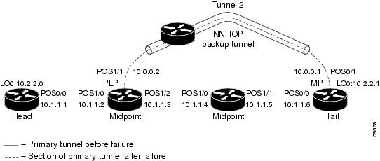
Figure 2 illustrates the network topology for the RSVP configuration example.

Figure 2 Network Topology for the RSVP Configuration Example

Example 1: The command is entered at the PLR before a failure.

The following is sample output from the show ip rsvp sender detail command when it is entered at the PLR before a failure:

Router# show ip rsvp sender detail 

PATH:
   Tun Dest: 10.2.2.1 Tun ID: 1 Ext Tun ID: 10.2.2.0
   Tun Sender: 10.2.2.0, LSP ID: 126
   Path refreshes arriving on POS1/0 from PHOP 10.1.1.1
   Path refreshes being sent to NHOP 10.1.1.4 on POS1/1
   Session Attr::
     Setup Prio: 0, Holding Prio: 0
     Flags: Local Prot desired, Label Recording, SE Style
     Session Name:tagsw4500-23_t1 
   ERO:
     10.1.1.4 (Strict IPv4 Prefix, 8 bytes, /32)
     10.1.1.5 (Strict IPv4 Prefix, 8 bytes, /32)
     10.1.1.6 (Strict IPv4 Prefix, 8 bytes, /32)
     10.2.2.1 (Strict IPv4 Prefix, 8 bytes, /32)
   Traffic params - Rate: 0G bits/sec, Max. burst: 1K bytes
   Fast-Reroute Backup info:
     Inbound  FRR: Not active
     Outbound FRR: Ready -- backup tunnel selected
       Backup Tunnel: Tu2        (label 0)
       Bkup Sender Template: 
         Tun Sender: 10.0.0.0, LSP ID: 126
       Bkup FilerSpec:       
         Tun Sender: 10.0.0.0, LSP ID 126

Table 13 describes the significant fields shown in the display.


Note The Flags field is important for Fast Reroute. For information about flags that must be set, see the Flags field description in Table 13.


Table 13 show ip rsvp sender detail Field Descriptions—on PLR Before Failure 

Field
Description

The first five fields provide information that uniquely identifies the LSP.

The first three fields identify the LSP's session (that is, the contents of the SESSION object in arriving PATH messages).

Tun Dest

IP address of the destination of the tunnel.

Tun ID

Tunnel identification number.

Ext Tun ID

Extended tunnel identification number.

The next two fields identify the LSP's sender (SENDER_TEMPLATE object of arriving PATH messages).

Tun Sender

Tunnel sender.

LSP ID

LSP identification number.

The remaining fields indented under PATH provide additional information about this LSP.

Session Attr—Session attributes. Refers to information included in the SESSION_ATTRIBUTE object of arriving PATH messages, such as the Setup and Holding Priorities, Flags, and the Session Name.

Setup Prio

Setup priority.

Holding Prio

Holding priority.

Flags

An LSP must have the "Local protection desired" flag of the SESSION_ATTRIBUTE object set for the LSP to use a backup tunnel (that is, in order to receive local protection). If this flag is not set, you have not enabled Fast Reroute for this tunnel at its headend (by entering the tunnel mpls traffic-eng fast-reroute command). NNHOP backup tunnels rely on label recording, so LSPs should have the "label recording desired" flag set too. This flag is set if the tunnel was configured for Fast Reroute.

ERO—Refers to the EXPLICIT_ROUTE Object (ERO) of the PATH messages. This field displays the contents of the ERO at this node. As a PATH message travels from the sender (headend) to the receiver (tailend), each node removes its own IP address from the ERO. The displayed value reflects the remainder of hops between this node and the tail.

Fast-Reroute Backup info—Information that is relevant to Fast Reroute for this LSP.

Inbound FRR

If this node is downstream from a rerouted LSP (for example, at a merge point for this LSP), the state is Active.

Outbound FRR

If this node is a PLR for an LSP, there are three possible states:

Active—This LSP is actively using its backup tunnel, presumably because there has been a downstream failure.

No Backup—This LSP does not have local (Fast Reroute) protection. No backup tunnel has been selected for it to use in case of a failure.

Ready—This LSP is ready to use a backup tunnel in case of a downstream link or node failure. A backup tunnel has been selected for it to use.

Backup Tunnel

If the Outbound FRR state is Ready or Active, this field indicates the following:

Which backup tunnel has been selected for this LSP to use in case of a failure.

The inbound label that will be prepended to the LSP's data packets for acceptance at the backup tunnel tail (the merge point).

Bkup Sender Template

If the Outbound FRR state is Ready or Active, SENDER_TEMPLATE and FILTERSPEC objects are shown. These objects will be used in RSVP messages sent by the backup tunnel if the LSP starts actively using the backup tunnel. They differ from the original (prefailure) objects only in that the node (the PLR) substitutes its own IP address for that of the original sender. For example, PATH and PATHTEAR messages will contain the new SENDER_TEMPLATE. RESV and RESVTEAR messages will contain the new FILTERSPEC object. If this LSP begins actively using the backup tunnel, the display changes.

Bkup FilerSpec

If the Outbound FRR state is Ready or Active, SENDER_TEMPLATE and FILTERSPEC objects are shown. These objects will be used in RSVP messages sent by the backup tunnel if the LSP starts actively using the backup tunnel. They differ from the original (prefailure) objects only in that the node (the PLR) substitutes its own IP address for that of the original sender. For example, PATH and PATHTEAR messages will contain the new SENDER_TEMPLATE. RESV and RESVTEAR messages will contain the new FILTERSPEC object. If this LSP begins actively using the backup tunnel, the display changes as shown in Example 2.


Example 2: The command is entered at the PLR after a failure.

If the LSP begins actively using the backup tunnel and the command is entered at the PLR after a failure, the display changes as shown below.

Router# show ip rsvp sender detail

PATH:
   Tun Dest: 10.2.2.1 Tun ID: 1 Ext Tun ID: 10.2.2.0
   Tun Sender: 10.2.2.0, LSP ID: 126
   Path refreshes arriving on POS1/0 from PHOP 10.1.1.1
   Path refreshes being sent to NHOP 10.2.2.1 on Tunnel2
   Session Attr::
     Setup Prio: 0, Holding Prio: 0
     Flags: Local Prot desired, Label Recording, SE Style
     Session Name:tagsw4500-23_t1 
   ERO:
     10.2.2.1 (Strict IPv4 Prefix, 8 bytes, /32)
     10.2.2.1 (Strict IPv4 Prefix, 8 bytes, /32)
   Traffic params - Rate: 0G bits/sec, Max. burst: 1K bytes
   Fast-Reroute Backup info:
     Inbound  FRR: Not active
     Outbound FRR: Active -- using backup tunnel
       Backup Tunnel: Tu2        (label 0)
       Bkup Sender Template: 
         Tun Sender: 10.0.0.0, LSP ID: 126
       Bkup FilerSpec:       
         Tun Sender: 10.0.0.0, LSP ID 126
       Orig Output I/F: Et2
       Orig Output ERO:
         10.1.1.4 (Strict IPv4 Prefix, 8 bytes, /32)
         10.1.1.5 (Strict IPv4 Prefix, 8 bytes, /32)
         10.1.1.6 (Strict IPv4 Prefix, 8 bytes, /32)
         10.2.2.1 (Strict IPv4 Prefix, 8 bytes, /32)

Once an LSP is actively using a backup tunnel, the following changes occur:

PATH refreshes are no longer sent to the original NHOP out the original interface. They are sent through the backup tunnel to the node that is the tail of the backup tunnel (NHOP or NNHOP).

The ERO is modified so that it will be acceptable upon arrival at the NHOP or NNHOP.

The display shows both the original ERO and the new one that is now being used.

The display shows the original output interface (that is, the interface from which PATH messages were sent for this LSP before the failure).

Example 3: The command is entered at the MP before a failure.

If the same show ip rsvp sender command is entered at the merge point (the backup tunnel tail), the display changes from before to after the failure. The following is sample output before a failure:

Router# show ip rsvp sender detail

PATH:
   Tun Dest: 10.2.2.1 Tun ID: 1 Ext Tun ID: 10.2.2.0
   Tun Sender: 10.2.2.0, LSP ID: 126
   Path refreshes arriving on POS0/0 from PHOP 10.1.1.5
   Session Attr::
     Setup Prio: 0, Holding Prio: 0
     Flags: Local Prot desired, Label Recording, SE Style
     Session Name:tagsw4500-23_t1 
   Traffic params - Rate: 0G bits/sec, Max. burst: 1K bytes
   Fast-Reroute Backup info:
     Inbound  FRR: Not active
     Outbound FRR: No backup tunnel selected

Example 4: The command is entered at the MP after a failure.

After a failure, the following changes occur:

The interface and previous hop (PHOP) from which PATH messages are received will change.

The inbound FRR becomes Active.

The original PHOP and the original input interface are displayed as shown below.

The following is sample output after a failure:

Router# show ip rsvp sender detail

PATH:
   Tun Dest: 10.2.2.1 Tun ID: 1 Ext Tun ID: 10.2.2.0
   Tun Sender: 10.2.2.0, LSP ID: 126
   Path refreshes arriving on POS0/1 from PHOP 10.0.0.0 on Loopback0
   Session Attr::
     Setup Prio: 0, Holding Prio: 0
     Flags: Local Prot desired, Label Recording, SE Style
     Session Name:tagsw4500-23_t1 
   Traffic params - Rate: 0G bits/sec, Max. burst: 1K bytes
   Fast-Reroute Backup info:
     Inbound  FRR: Active
       Orig Input I/F: POS0/0
       Orig PHOP: 10.1.1.5
       Now using Bkup Filterspec w/ sender: 10.0.0.0 LSP ID: 126
     Outbound FRR: No backup tunnel selected

Notice the following changes:

After a failure, PATH refreshes arrive on a different interface and from a different PHOP.

The original PHOP and input interface are shown under Fast-Reroute Backup information, along with the FILTERSPEC object that will now be used when sending messages (such as RESV and RESVTEAR).

Example 5: The command output shows all senders.

In the following example, information about all senders is displayed.

Router# show ip rsvp sender

To              From              Pro DPort Sport Prev Hop        I/F  BPS  Bytes
10.2.2.1        10.2.2.0          1   1     59    10.1.1.1        Et1   0G     1K
10.2.2.1        172.31.255.255    1   2     9                           0G     1K
10.2.2.1        10.2.2.0          1   3     12    10.1.1.1        Et1   0G     1K
10.2.2.1        172.31.255.255    1   3     20                          0G     1K
172.16.0.0      172.31.255.255    1   0     23                          0G     1K
172.16.0.0      172.31.255.255    1   1     22                          0G     1K
172.16.0.0      172.31.255.255    1   1000  22                          0G     1K

Table 14 describes the significant fields shown in the display.

Table 14 show ip rsvp sender Field Descriptions 

Field
Description

To

IP address of the receiver.

From

IP address of the sender.

Pro

Protocol code. Code 1 indicates Internet Control Message Protocol (ICMP).

DPort

Destination port number.

Sport

Source port number.

Prev Hop

IP address of the previous hop.

I/F

Interface of the previous hop.

BPS

Reservation rate, in bits per second, that the application is advertising it might achieve.

Bytes

Bytes of burst size that the application is advertising it might achieve.


Example 6: The command output shows only senders having a specific destination.

To show only information about senders having a specific destination, specify the destination filter as shown below. In this example, the destination is 172.16.0.0.

Router# show ip rsvp sender filter destination 172.16.0.0

To          From         Pro DPort Sport Prev Hop    I/F  BPS  Bytes
172.16.0.0  172.31.255   1   0     23                      0G     1K
172.16.0.0  172.31.255   1   1     22                      0G     1K
172.16.0.0  172.31.255   1   1000  22                      0G     1K

Example 7: Show more detail about a sender having a specific destination.

To show more detail about the sender whose destination port is 1000 (as shown in Example 6), specify the command with the destination port filter:

Router# show ip rsvp sender filter detail dst-port 1000

PATH:
  Tun Dest 172.16.0.0 Tun ID 1000 Ext Tun ID 172.31.255.255
  Tun Sender: 172.31.255.255, LSP ID: 22
  Path refreshes being sent to NHOP 10.1.1.4 on Ethernet2
  Session Attr::
    Setup Prio: 7, Holding Prio: 7
    Flags: SE Style
    Session Name:tagsw4500-25_t1000 
  ERO:
    10.1.1.4 (Strict IPv4 Prefix, 8 bytes, /32)
    172.16.0.0 (Strict IPv4 Prefix, 8 bytes, /32)
  Traffic params - Rate: 0G bits/sec, Max. burst: 1K bytes
  Fast-Reroute Backup info:
    Inbound  FRR: Not active
    Outbound FRR: No backup tunnel selected

Related Commands

Command
Description

ip rsvp sender

Enables a router to simulate RSVP PATH message reception from the sender.

show ip rsvp reservation

Displays RSVP PATH-related receiver information currently in the database.


show ip rsvp signalling fast-local-repair

To display fast-local-repair (FLR)-specific information maintained by Resource Reservation Protocol (RSVP), use the show ip rsvp signalling fast-local-repair command in user EXEC or privileged EXEC mode.

show ip rsvp signalling fast-local-repair [statistics [detail]]

Syntax Description

statistics

(Optional) Displays information about FLR procedures.

detail

(Optional) Displays additional information about FLR procedures.


Command Default

Information for the FLR and RSVP message pacing displays.

Command Modes

User EXEC
Privileged EXEC

Command History

Release
Modification

12.2(33)SRB

This command was introduced.


Usage Guidelines

Use the show ip rsvp signalling fast-local-repair command to display the FLR and RSVP message pacing rates that are configured.

Use the show ip rsvp signalling fast-local-repair statistics command to display the FLR procedures and related information including the following:

The process number

The state

The start time

The number of path state blocks (PSBs) repaired

The repair rate

The routing information base (RIB) notification process time

The repair time of the last PSB

Use the show ip rsvp signalling fast-local-repair statistics detail command to display detailed information about FLR procedures including the following:

The time of the routing notification

The elapsed time for processing all notifications in the queue

The rate and pacing unit (the refresh spacing in ms) used

The number of PSBs repaired

The number of times RSVP has suspended

For each run, the following information appears:

The time that the run started relative to the start of the procedure

The time that RSVP suspended again

The number of notifications processed in this run

For each neighbor, the following information appears:

The delay of the first PATH message sent to this neighbor

The delay of the last PATH message sent to this neighbor

Examples

show ip rsvp signalling fast-local-repair Example

The following example displays information about the FLR rate:

Router# show ip rsvp signalling fast-local-repair

Fast Local Repair: enabled
   Max repair rate (paths/sec): 400
   Max processed   (paths/run): 1000

Table 15 describes the significant fields shown in the display.

Table 15 show ip rsvp signalling fast-local-repair Field Descriptions 

Field
Description

Fast Local Repair

FLR state. Values are the following:

Enabled—FLR is configured.

Disabled—FLR is not configured.

Max repair rate (paths/sec)

Maximum repair rate, in paths per second.

Max processed (paths/run)

Maximum notification elements processed, in paths per run.


show ip rsvp signalling fast-local-repair statistics Example

The following example displays information about FLR procedures:

Router# show ip rsvp signalling fast-local-repair statistics

Fast Local Repair: enabled
   Max repair rate (paths/sec): 1000
   Max processed   (paths/run): 1000

FLR Statistics:

  FLR   State    Start                          #PSB   Repair RIB Proc Last
  Proc.          Time                           Repair Rate   Time     PSB
  1     DONE     15:16:32 MET Wed Oct 25 2006   2496   1000   91(ms)   3111(ms)

Table 16 describes the significant fields shown in the display.

Table 16 show ip rsvp signalling fast-local-repair statistics Field Descriptions 

Field
Description

Fast Local Repair

FLR state. Values are the following:

Enabled—FLR is configured.

Disabled—FLR is not configured.

Max repair rate (paths/sec)

Maximum repair rate, in paths per second.

Max processed (paths/run)

Maximum notification elements processed, in paths per run.

FLR Statistics

FLR-related information.

FLR Proc.

FLR procedure number. The last 32 procedures are listed from the most recent to the oldest; they are numbered from 1 to 32.

State

Current state of the FLR procedure. Values are the following:

DONE—The FLR procedure is complete.

IN PROGRESS—The FLR procedure is incomplete.

Start Time

Time when RSVP received the routing notification.

#PSB Repair

Number of PSBs repaired.

Repair Rate

Repair rate used, in paths per second.

RIB Proc Time

Time that RSVP spent to process all RIB notifications and schedule the path refreshes, in microseconds (us), milliseconds (msec or ms), or seconds (sec).

Note The value is converted to fit the column width; however, seconds are rarely used because RSVP RIB notification processing is very fast.

Last PSB

Elapsed time, in microseconds (us), milliseconds (msec or ms), or seconds (sec), between the start of an FLR procedure and when RSVP sent the last PATH message.

Note The value is converted to fit the column width; however, seconds are rarely used because RSVP RIB notification processing is very fast.


show ip rsvp signalling fast-local-repair statistics detail Example

The following example displays detailed information about FLR procedures:

Router# show ip rsvp signalling fast-local-repair statistics detail

Fast Local Repair: enabled
   Max repair rate (paths/sec): 1000
   Max processed   (paths/run): 1000

FLR Statistics:

   FLR 1: DONE
     Start Time: 15:16:32 MET Wed Oct 25 2006
     Number of PSBs repaired:          2496
     Used Repair Rate (msgs/sec):      1000
     RIB notification processing time: 91(ms)
     Time of last PSB refresh:         3111(ms)
     Time of last Resv received:       4355(ms)
     Time of last Perr received:       0(us)
     Suspend count: 2
       Run  Number   Started              Duration
       ID   of ntf.  (time from Start)
       2    498      81(ms)               10(ms)
       1    998      49(ms)               21(ms)
       0    1000     0(us)                22(ms)
     FLR Pacing Unit: 1 msec
     Affected neighbors:
       Nbr Address           Relative Delay Values (msec)
       10.1.0.70             [500   ,..., 2995  ]

Table 17 describes the significant fields shown in the display.

Table 17 show ip rsvp signalling fast-local-repair statistics detail Field Descriptions 

Field
Description

Fast Local Repair

FLR state. Values are the following:

Enabled—FLR is configured.

Disabled—FLR is not configured.

Max repair rate (paths/sec)

Maximum repair rate, in paths per second.

Max processed (paths/run)

Maximum notification elements processed, in paths per run.

FLR Statistics

FLR-related information.

FLR #

FLR procedure number and current state. The last 32 procedures are listed from the most recent to the oldest; they are numbered from 1 to 32. Values for the state are the following:

DONE—The FLR procedure is complete.

IN PROGRESS—The FLR procedure is incomplete.

Start Time

Time when RSVP received the routing notification.

Number of PSBs repaired

Total PSBs repaired.

Used Repair Rate (msgs/sec)

Repair rate used, in messages per second.

RIB notification processing time

Time, in milliseconds (ms), that RSVP spent to process all RIB notifications.

Time of last PSB refresh

Elapsed time, in milliseconds (ms), between the start of an FLR procedure and when RSVP sent the last PATH refresh message.

Time of last Resv received

Elapsed time, in milliseconds (ms), between the start of an FLR procedure and when RSVP received the last RESV message.

Time of last Perr received

Elapsed time, in microseconds (us), between the start of an FLR procedure and when RSVP received the last PATHERROR message.

Suspend count

Number of times that RSVP has suspended during a specific procedure.

Note If this value is non-zero, details for each run are shown.

Run ID

Identifier (number) for each time that RSVP has run.

Number of ntf.

Number of notifications (PSBs) processed in a run.

Started (time from Start)

Time, in milliseconds (ms), that the run began relative to the start of the FLR procedure.

Duration

Length of time, in milliseconds (ms), for the run.

FLR Pacing Unit

Frequency, in milliseconds (msec), for RSVP message pacing; that is, how often a PATH message is sent. The value is rounded down.

Affected neighbors

Neighbors involved in the FLR procedure.

Nbr Address

IP address for each neighbor involved in a procedure.

Relative Delay Values

Times, in milliseconds (msec), when the PSB refreshes were sent.

Note In the sample display, there is a 1-msec pacing unit; therefore, PSBs to 10.1.0.70 have been sent with delays of 1 msec from 500, 501, 502, 503, ... 2995. If a 5-msec pacing unit were used, the delays would be 500, 505, 510,... 2990, 2995.


Related Commands

Command
Description

ip rsvp signalling fast-local-repair notifications

Configures the number of notifications that are processed before RSVP suspends.

ip rsvp signalling fast-local-repair rate

Configures the repair rate that RSVP uses for an FLR procedure.

ip rsvp signalling fast-local-repair wait

Configures the delay used to start an FLR procedure.

ip rsvp signalling rate-limit

Controls the transmission rate for RSVP messages sent to a neighboring router during a specified amount of time.


Feature Information for RSVP FLR

Table 18 lists the release history for this feature.

Not all commands may be available in your Cisco IOS software release. For release information about a specific command, see the command reference documentation.

Use Cisco Feature Navigator to find information about platform support and software image support. Cisco Feature Navigator enables you to determine which Cisco IOS and Catalyst OS software images support a specific software release, feature set, or platform. To access Cisco Feature Navigator, go to http://www.cisco.com/go/cfn. An account on Cisco.com is not required.


Note Table 18 lists only the Cisco IOS software release that introduced support for a given feature in a given Cisco IOS software release train. Unless noted otherwise, subsequent releases of that Cisco IOS software release train also support that feature.


Table 18 Feature Information for RSVP FLR

Feature Name
Releases
Feature Information

RSVP Fast Local Repair

12.2(33)SRB

The RSVP Fast Local Repair feature provides quick adaptation to routing changes without the overhead of the refresh period to guarantee QoS for data flows. With FLR, RSVP speeds up its response to routing changes from 30 seconds to a few seconds.


Glossary

admission control—The process by which an RSVP reservation is accepted or rejected on the basis of end-to-end available network resources.

bandwidth—The difference between the highest and lowest frequencies available for network signals. The term is also used to describe the rated throughput capacity of a given network medium or protocol.

message pacing—A system for managing volume and timing that permits messages from multiple sources to be spaced apart over time. RSVP message pacing maintains, on an outgoing basis, a count of the messages that it has been forced to drop because the output queue for the interface used for the message pacing was full.

MP—merge point. The node where the new and old FLR segments meet.

PLR—point of local repair. The node that initiates an FLR procedure.

QoS—quality of service. A measure of performance for a transmission system that reflects its transmission quality and service availability.

RSVP—Resource Reservation Protocol. A protocol that supports the reservation of resources across an IP network. Applications running on IP end systems can use RSVP to indicate to other nodes the nature (bandwidth, jitter, maximum burst, and so on) of the packet streams that they want to receive.


Note See Internetworking Terms and Acronyms for terms not included in this glossary.