Downloads |
 Feedback Feedback
|
Table Of Contents
Prerequisites for NDE for VRF Interfaces
Restrictions for NDE for VRF Interfaces
Information About NDE for VRF Interfaces
Example of an MPLS VPN Network
Analysis of Traffic Exiting the MPLS VPN Network with NetFlow
More Than 511 Stored MPLS Aggregate Labels
MPLS Aggregate Labels in VPN CAM
MPLS Aggregate Labels Not in VPN CAM
Configuring MPLS VPN Netflow Capture and Export
VRF Name as the Source Interface in the NetFlow Cache
How to Configure NDE for VRF Interfaces for an MPLS VPN
Configuration Examples for NDE for VRF Interfaces
Configurations for the Example Network with One MPLS VPN: Example
Configuring the NDE for VRF Interfaces Feature on a VRF: Example
show ip cache flow aggregation
Feature Information for NDE for VRF Interfaces
NDE for VRF Interfaces
First Published: February 27th, 2007Last Updated: February 27th, 2007The NetFlow data export (NDE) for VRF Interfaces feature enables the creation and export of hardware NetFlow cache entries for traffic entering a router on the last multi-protocol label switching (MPL)S hop of an IPv4 MPLS virtual private network (VPN). The NDE for VRF Interfaces feature also ensures that the data collected in the hardware NetFlow cache for traffic that is received on an IPv4 interface configured for a per-site forwarding table (VRF) contains the routing information specific to the VRF.
Finding Feature Information in This Module
Your Cisco IOS software release may not support all of the features documented in this module. To reach links to specific feature documentation in this module and to see a list of the releases in which each feature is supported, use the "Feature Information for NDE for VRF Interfaces" section.
Finding Support Information for Platforms and Cisco IOS and Catalyst OS Software Images
Use Cisco Feature Navigator to find information about platform support and Cisco IOS and Catalyst OS software image support. To access Cisco Feature Navigator, go to http://www.cisco.com/go/cfn. An account on Cisco.com is not required.
Contents
•
Prerequisites for NDE for VRF Interfaces
•
•
•
•
•
Prerequisites for NDE for VRF Interfaces
Your router must be running Cisco IOS release 12.2(33)SRB or later to configure the NDE for VRF Interfaces feature.
Restrictions for NDE for VRF Interfaces
The NDE for VRF Interfaces feature supports only IPv4 traffic.
When you configure the NDE for VRF Interfaces feature for a MPLS VPN, the router assigns a reserved VLAN ID to the MPLS VPN. This will limit the number of VLAN IDs available for other features that you configure on the router and that require VLAN IDs.
Information About NDE for VRF Interfaces
Before configuring the NDE for VRF Interfaces feature, you should understand the following concepts:
•
•
•
Example of an MPLS VPN Network
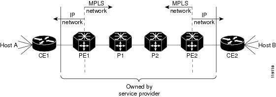
Figure 1 is an example of a simple MPLS virtual private network (VPN). Routers PE1 and PE2 are configured to support an MPLS VPN to carry the customer's traffic between the sites where routers CE1 and CE2 are located. Routers PE1 and PE2 use multi-protocol iBGP peers for routing traffic on the MPLS VPNs. The NDE for VRF Interfaces feature is applicable to routers PE1 and PE2 in this example.
Figure 1 Example of a simple MPLS VPN network
For more information about configuring MPLS on Cisco 7600 series routers, see the "Configuring PFC3BXL and PFC3B Multiprotocol Label Switching (MPLS)" chapter in the Catalyst 7600 Series Cisco IOS Software Configuration Guide, Release 12.2SR.
Analysis of Traffic Exiting the MPLS VPN Network with NetFlow
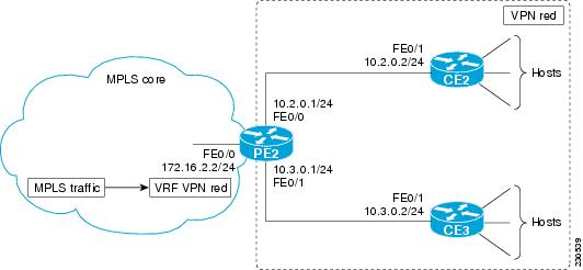
The NDE for VRF Interfaces feature captures traffic received by the router on the MPLS VPN VRF interface as it exits the MPLS network. For example, when you configure the NDE for VRF Interfaces feature on VPN Red on PE2 as shown in Figure 2, and the traffic to and from CE2 is assigned to VRF Red, the traffic is added to the NetFlow cache and shown as being received on VPN Red.
Figure 2 Example of a Router (PE2) Receiving Traffic over a MPLS VPN VRF Interface
MPLS Aggregate Labels
There are two types of VPN MPLS labels:
•
•
When you configure a MPLS VPN on a PE router the router allocates an aggregate MPLS label for the VPN.
Since aggregate MPLS labels correspond to the VRF to which a packet belongs, the router must consult the routing table for a VRF to determine the correct next hop IP address within the VPN domain in order to forward the packet. The next-hop IP address is required before the router can forward the packet because VPN domains are capable of supporting multiple next hop routers. For example, in Figure 2 there are two CE routers: CE2 and CE3. MPLS traffic arriving on VPN Red on PE1 could be destined to hosts attached to either CE2 or CE3. PE2 must perform another lookup to identify the correct CE router to which the traffic must be forwarded. The method that PE2 uses to perform the next-hop IP address lookup depends on the number of MPLS aggregate labels that the router has stored.
Stored MPLS Aggregate Labels
Traffic that uses one of the first 511 aggregate MPLS labels is forwarded by the router based on the entry for the MPLS VPN label in the VPN content addressable memory (CAM).
The following steps are performed by a PE router to forward MPLS traffic that uses one of the first 511 aggregate MPLS labels:
1.
2.
3.
4.
5.
More Than 511 Stored MPLS Aggregate Labels
When the number of MPLS aggregate labels in the network exceeds 511, the router can no longer store some MPLS aggregate labels in its VPN CAM. In this situation the router consults the MPLS FIB, strips off the label to reveal the IPv4 packet encapsulated inside, and recirculates the packet, at which point the VRF FIB determines the next hop.
Note
The following steps are performed by a PE router to forward MPLS traffic when the aggregate MPLS label is not in the VPN CAM:
1.
2.
Note
3.
4.
NetFlow Cache Population
When the NDE for VRF Interfaces feature is configured for an MPLS VPN, a VLAN interface is reserved and NetFlow is enabled on the VLAN interface. The method used by the router to process the MPLS VPN IPv4 traffic and populate the NetFlow cache depends on the number of MLS aggregate labels that the router has stored.
MPLS Aggregate Labels in VPN CAM
When there are fewer than 512 VPN aggregate MPLS labels, the label and associated VPN are programmed in the MPLS VPN CAM, and packet recirculation is not required. The policy feature card (PFC) receives the packet as an IP packet. The PFC NetFlow function sees flows as sourced at the MPLS VPN not at the interface on which the traffic was received.
When there are fewer than 512 VPN aggregate MPLS labels (all MPLS aggregate labels are stored in the VPN CAM), the NetFlow cache is populated for the MPLS traffic that is using the MPLS aggregate labels by enabling NetFlow on the MPLS interface with the ip flow ingress command. For example, to enable NetFlow for the traffic that is being forwarded based on the MPLS aggregation labels in the VPN CAM in router PE2 in Figure 2, you must configure the ip flow ingress command on interface FastEthernet0/0. This is sufficient to populate the cache. To cause the router to export the NetFlow data to a collector, the flow hardware mpls-vpn ip vrf-id command must be issued in global configuration mode.
MPLS Aggregate Labels Not in VPN CAM
When the number of MPLS aggregate labels in the network exceeds 511, the VPN CAM is full. Traffic must be recirculated if it does not use one of the MPLS aggregate labels stored in the VPN CAM. The packets are processed by the policy feature card (PFC) once to strip the MPLS label, and processed by the PFC a second time with the VLAN specified as the reserved VPN VLAN that was assigned when the NDE for VRF Interfaces feature was enabled. The VLAN RAM maps this VLAN to the VPN for use in routing. The PFC netflow function sees flows as sourced at the reserved VRF VLAN. The ternary content addressable memory (TCAM) entry for the reserved VLAN interface provides the flow mask to NetFlow.
Flows for MPLS VPN traffic received with aggregate label that is not in the VPN CAM are populated in the NetFlow cache by configuring the flow hardware mpls-vpn ip vrf-id command for each VPN VRF on the router in global configuration mode.
MPLS-Specific Labels
For the nonaggregate label case, by definition, the router does not need to examine the underlying IP packet to determine where to route the packet. In order to cause the IP flows to populate the cache, the flow hardware mpls-vpn ip vrf-id configuration command must be entered. This causes the specific label flow traffic to be stripped of its label and recirculated to the reserved VPN VLAN prior to being forwarded to the exit interface. This introduces more delay in forwarding the traffic than would otherwise be experienced.
Configuring MPLS VPN Netflow Capture and Export
To ensure that you have enabled the capturing and export of NetFlow data for all of the traffic that you want to analyze, regardless of the MPLS aggregate label it is using, you should configure the ip flow ingress command on the MPLS interface and configure the flow hardware mpls-vpn ip vrf-id command for each VPN VRF on the router in global configuration mode.
Note
VRF Name as the Source Interface in the NetFlow Cache
For traffic received for an MPLS VPN on an MPLS interface, the source interface for the traffic in the NetFlow cache is listed as the VPN name, not the physical interface on which the traffic was received. For example, traffic being received on FastEthernet0/0 on PE2 in Figure 2 will be displayed in the NetFlow cache on the router as being received over VPN Red, not interface FastEthernet0/0.
How to Configure NDE for VRF Interfaces for an MPLS VPN
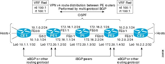
Perform this task to configure the NDE for VRF Interfaces feature on an MPLS VPN. This configuration is appropriate for the router named PE1 in Figure 3. Repeat this task on router PE2 but remember to change the interface references to the appropriate interfaces for PE2.
Note
Figure 3 Example Network with One MPLS VPN
SUMMARY STEPS
1.
2.
3.
4.
5.
6.
7.
8.
9.
10.
11.
12.
13.
14.
15.
16.
17.
18.
19.
20.
21.
22.
23.
DETAILED STEPS
Examples
The following output of the show mls nde command displays the NDE configuration and statistics.
PE1# show mls ndeNetflow Data Export enabledExporting flows to 172.16.2.6 (99)Exporting flows from 172.16.1.2 (51203)Version: 9Layer2 flow creation is disabledLayer2 flow export is disabledInclude Filter not configuredExclude Filter not configuredTotal Netflow Data Export Packets are:4 packets, 0 no packets, 19 recordsTotal Netflow Data Export Send Errors:IPWRITE_NO_FIB = 0IPWRITE_ADJ_FAILED = 0IPWRITE_PROCESS = 0IPWRITE_ENQUEUE_FAILED = 0IPWRITE_IPC_FAILED = 0IPWRITE_OUTPUT_FAILED = 0IPWRITE_MTU_FAILED = 0IPWRITE_ENCAPFIX_FAILED = 0Netflow Aggregation DisabledPE1#The following output of the show mls netflow ip module command displays the Netflow entries in the PFC. The first row of output shows traffic on VPN red.
Note
Router# show mls netflow ip module 5Displaying Netflow entries in module 5DstIP SrcIP Prot:SrcPort:DstPort Src i/f :AdjPtr-----------------------------------------------------------------------------Pkts Bytes Age LastSeen Attributes---------------------------------------------------10.1.1.1 10.2.0.2 0 :0 :0 vpn:red :0x0504 398020 1 23:20:48 L3 - Dynamic224.0.0.5 172.16.1.1 89 :0 :0 Fa1/1 :0x01 84 7 23:20:42 L2 - Dynamic0.0.0.0 0.0.0.0 0 :0 :0 -- :0x02238 1582910 33 23:20:48 L3 - Dynamic224.0.0.2 172.16.1.1 udp :646 :646 Fa1/1 :0x05 310 21 23:20:46 L2 - Dynamic172.16.2.6 172.16.1.2 0 :0 :0 Fa1/1 :0x01 140 22 23:20:27 L2 - DynamicRouter#The following output of the show ip cache flow command displays the data in the NetFlow cache. The last line of data in the output shows that the source interface for this traffic is VPN Red.
PE1# show ip cache flow-------------------------------------------------------------------------------MSFC:IP packet size distribution (3139 total packets):1-32 64 96 128 160 192 224 256 288 320 352 384 416 448 480.000 .685 .309 .000 .000 .000 .000 .003 .000 .000 .000 .000 .000 .000 .000512 544 576 1024 1536 2048 2560 3072 3584 4096 4608.000 .000 .000 .000 .000 .000 .000 .000 .000 .000 .000IP Flow Switching Cache, 278544 bytes2 active, 4094 inactive, 56 added20904 ager polls, 0 flow alloc failuresActive flows timeout in 30 minutesInactive flows timeout in 15 secondsIP Sub Flow Cache, 33992 bytes0 active, 1024 inactive, 4 added, 4 added to flow0 alloc failures, 0 force free1 chunk, 2 chunks addedlast clearing of statistics neverProtocol Total Flows Packets Bytes Packets Active(Sec) Idle(Sec)-------- Flows /Sec /Flow /Pkt /Sec /Flow /FlowTCP-BGP 10 0.0 1 49 0.0 0.0 15.3TCP-other 6 0.0 2 49 0.0 4.5 15.5UDP-other 28 0.0 74 63 0.1 320.5 12.7IP-other 6 0.0 153 80 0.0 1488.3 1.7Total: 50 0.0 60 68 0.2 358.6 12.2SrcIf SrcIPaddress DstIf DstIPaddress Pr SrcP DstP PktsFa1/1 172.16.1.1 Null 224.0.0.2 11 0286 0286 74Fa1/1 172.16.1.1 Null 224.0.0.5 59 0000 0000 33-------------------------------------------------------------------------------PFC:Displaying Hardware entries in Module 5SrcIf SrcIPaddress DstIPaddress Pr SrcP DssFa1/1 172.20.1.2 172.20.1.3 0 0 0Fa1/1 172.20.1.3 172.20.1.2 0 0 0Fa1/1 172.16.1.2 172.16.2.6 0 0 0Fa1/1 172.16.1.1 224.0.0.2 udp 646 64-- 0.0.0.0 0.0.0.0 0 0 0vpn:red 10.2.0.2 10.1.1.1 0 0 0...PE1#Configuration Examples for NDE for VRF Interfaces
The following configuration example shows how to configure a simple network topology with the NDE for VRF Interfaces feature configured on two PE routers.
This section contains the following example configurations:
•
•
Configurations for the Example Network with One MPLS VPN: Example
This section contains the configurations for all of the devices in Figure 3. The NDE for VRF Interfaces feature is configured on routers PE1 and PE2.
CE1
!hostname CE1!ip cef!interface Loopback0no shutdownip address 10.1.1.1 255.255.255.255!interface FastEthernet0/0no shutdownip address 10.1.0.2 255.255.255.0!ip default-network 0.0.0.0ip route 0.0.0.0 0.0.0.0 10.1.0.1!endPE1
!hostname PE1!ip cef distributed!mls nde sendermls flow ip interface-destination-sourceip flow-export destination 172.16.2.6 99ip flow-export version 9!ip vrf redrd 200:2route-target export 200:20route-target import 200:20!flow hardware mpls-vpn ip red!multilink bundle-name authenticatedmpls label protocol ldp!interface Loopback0ip address 172.20.1.2 255.255.255.255!interface gigabitEthernet5/2no shutdownip vrf forwarding redip address 10.1.0.1 255.255.255.0!interface FastEthernet1/1no shutdowninterface FastEthernet1/1ip address 172.16.1.2 255.255.255.0ip flow ingressmpls ip!router ospf 100router-id 172.20.1.2log-adjacency-changesnetwork 172.16.0.0 0.0.255.255 area 0network 172.20.1.2 0.0.0.0 area 0!router bgp 200no synchronizationbgp log-neighbor-changesnetwork 172.0.0.0 mask 255.0.0.0neighbor as200 peer-groupneighbor as200 remote-as 200neighbor as200 description as200neighbor as200 update-source Loopback0neighbor as200 route-reflector-clientneighbor 172.20.1.4 remote-as 200neighbor 172.20.1.4 description iBGP with r4neighbor 172.20.1.4 update-source Loopback0no auto-summary!address-family vpnv4neighbor 172.20.1.4 activateneighbor 172.20.1.4 send-community bothexit-address-family!address-family ipv4 vrf redno synchronizationnetwork 10.1.0.0 mask 255.255.255.0network 10.1.1.1 mask 255.255.255.255exit-address-family!ip route 172.0.0.0 255.0.0.0 Null0ip route vrf red 10.1.1.1 255.255.255.255 10.1.0.2!mpls ldp router-id Loopback0!endP1
!hostname P1!ip cef!no ip domain lookup!mpls label protocol ldp!interface Loopback0no shutdownip address 172.20.1.3 255.255.255.255!interface FastEthernet0/0no shutdownip address 172.16.2.1 255.255.255.0mpls ip!interface FastEthernet0/1no shutdownip address 172.16.1.1 255.255.255.0mpls ip!router ospf 100router-id 172.20.1.3log-adjacency-changesnetwork 172.16.0.0 0.0.255.255 area 0network 172.20.1.3 0.0.0.0 area 0!mpls ldp router-id Loopback0!endPE2
!hostname PE2!ip cef distributed!mls nde sendermls flow ip interface-destination-sourceip flow-export destination 172.16.2.6 99ip flow-export version 9!ip vrf redrd 200:2route-target export 200:20route-target import 200:20!flow hardware mpls-vpn ip red!multilink bundle-name authenticatedmpls label protocol ldp!interface Loopback0no shutdownip address 172.20.1.4 255.255.255.255!interface FastEthernet0/0no shutdownip address 172.16.2.2 255.255.255.0mpls ipip flow ingress!interface FastEthernet0/1no shutdownip vrf forwarding redip address 10.2.0.1 255.255.255.0!router ospf 100router-id 172.20.1.4log-adjacency-changesnetwork 172.16.0.0 0.0.255.255 area 0network 172.20.1.4 0.0.0.0 area 0!router bgp 200no synchronizationbgp log-neighbor-changesnetwork 172.0.0.0 mask 255.0.0.0neighbor as200 peer-groupneighbor as200 remote-as 200neighbor as200 description as200neighbor as200 update-source Loopback0neighbor as200 route-reflector-clientneighbor 172.20.1.2 remote-as 200neighbor 172.20.1.2 description iBGP with r2neighbor 172.20.1.2 update-source Loopback0no auto-summary!address-family vpnv4neighbor 172.20.1.2 activateneighbor 172.20.1.2 send-community bothexit-address-family!address-family ipv4 vrf redno synchronizationnetwork 10.2.0.0 mask 255.255.255.0network 10.2.2.2 mask 255.255.255.255exit-address-family!ip route 172.0.0.0 255.0.0.0 Null0ip route vrf red 10.2.2.2 255.255.255.255 10.2.0.2!mpls ldp router-id Loopback0!endCE2
!hostname CE2!ip cef!interface Loopback0no shutdownip address 10.2.2.2 255.255.255.255!interface FastEthernet0/1no shutdownip address 10.2.0.2 255.255.255.0!ip default-network 0.0.0.0ip route 0.0.0.0 0.0.0.0 10.2.0.1!endConfiguring the NDE for VRF Interfaces Feature on a VRF: Example
This example configuration shows how to configure the NDE for VRF Interfaces feature for a VRF. When you enable NetFlow on interface GigabitEthernet2/3 with the ip flow ingress command, the NetFlow cache will contain information for traffic for VPN vpn1.
PE1
!ip vrf vpn1rd 100:1route-target export 100:1route-target import 100:1!mls flow ip interface-full!interface GigabitEthernet2/3ip vrf forwarding vpn1ip address 10.0.0.1 255.0.0.0ip flow ingress!interface GigabitEthernet2/7ip vrf forwarding vpn1ip address 172.16.20.1 255.255.255.0!ip flow-export version 9ip flow-export destination 192.168.10.2 20000endWhere to Go Next
•
•
Additional References
The following sections provide references related to the NDE for VRF Interfaces feature.
Related Documents
NetFlow commands, complete command syntax, command mode, defaults, command history, usage guidelines, and examples.
Information for configuring NetFlow, MPLS, and other features on Cisco 7600 series routers.
Cisco 7600 Series Cisco IOS Software Configuration Guide, Release 12.2SR
Standards
No new or modified standards are supported by this feature, and support for existing standards has not been modified by this feature.
—
MIBs
RFCs
No new or modified RFCs are supported by this feature, and support for existing RFCs has not been modified by this feature.
—
Technical Assistance
Command Reference
This section documents new and modified commands only.
•
flow hardware mpls-vpn ip
To ensure the creation and export of hardware NetFlow cache entries for traffic entering the router on the last MPLS hop of an IPv4 MPLS VPN network, use the flow hardware mpls-vpn ip command in global configuration mode. To disable the creation and export of hardware NetFlow cache entries for this traffic, use the no form of this command.
flow hardware mpls-vpn ip vrf-id
no flow hardware mpls-vpn ip vrf-id
Syntax Description
Command Default
Creation and export of hardware NetFlow cache entries for traffic entering the router on the last MPLS hop of an IPv4 MPLS VPN network is not enabled.
Command Modes
Global configuration
Command History
Usage Guidelines
NetFlow Aggregation
If you want to include IPV4 MPLS VPN traffic in a NetFlow aggregation scheme on your router, you must configure the flow hardware mpls-vpn ip command.
NetFlow Sampling
If you want to include IPV4 MPLS VPN traffic in the traffic that is analyzed using NetFlow sampling on your router, you must configure the flow hardware mpls-vpn ip command.
Examples
The following example configures NDE for VRF vpn1:
Router(config)# flow hardware mpls-vpn ip vpn1Related Commands
show ip cache flow
To display a summary of the NetFlow accounting statistics, use the show ip cache flow command in user EXEC or privileged EXEC mode.
show ip cache flow
Syntax Description
This command has no keywords or arguments.
Command Modes
User EXEC
Privileged EXECCommand History
Usage Guidelines
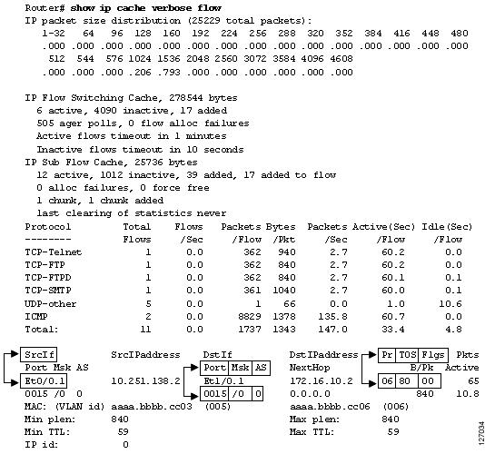
Some of the content in the display of the show ip cache flow command uses multiline headings and multiline data fields. Figure 5 shows how to associate the headings with the correct data fields when there are two lines of headings and two lines of data fields. The first line of the headings is associated with the first line of data fields. The second line of the headings is associated with the second line of data fields.
When other features such as IP Multicast are configured, the number of lines in the headings and data fields increases. The method for associating the headings with the correct data fields remains the same.
Figure 4 How to Use the Multiline Headings and Multiline Data Fields in the Display Output of the show ip cache flow Command
Displaying Detailed NetFlow Cache Information on Platforms Running Distributed Cisco Express Forwarding
On platforms running distributed Cisco Express Forwarding (dCEF), NetFlow cache information is maintained on each line card or Versatile Interface Processor. To display this information on a distributed platform by use of the show ip cache flow command, you must enter the command at a line card prompt.
Cisco 7600 Series Platforms
The module num keyword and argument are supported on DFC-equipped modules only.
The VPN name and ID are shown in the display output in the format VPN:vpn-id.
Cisco 7500 Series Platform
The Cisco 7500 series platorms are not supported by Cisco IOS Release 12.4T and later. Cisco IOS Release 12.4 is the last Cisco IOS release to support the Cisco 7500 series platorms.
To display NetFlow cache information using the show ip cache flow command on a Cisco 7500 series router that is running dCEF, enter the following sequence of commands:
Router# if-con slot-numberLC-slot-number# show ip cache flowFor Cisco IOS Releases 12.3(4)T, 12.3(6), and 12.2(20)S and later, enter the following command to display NetFlow cache information:
Router# execute-on slot-number show ip cache flowCisco 12000 Series Platform
To display NetFlow cache information using the show ip cache flow command on a Cisco 12000 Series Internet Router, enter the following sequence of commands:
Router# attach slot-numberLC-slot-number# show ip cache flowFor Cisco IOS Releases 12.3(4)T, 12.3(6), and 12.2(20)S and later, enter the following command to display NetFlow cache information:
Router# execute-on slot-number show ip cache flowExamples
The following is a sample display of a main cache using the show ip cache flow command:
Router# show ip cache flowIP packet size distribution (2381 total packets):1-32 64 96 128 160 192 224 256 288 320 352 384 416 448 480.092 .000 .003 .000 .141 .048 .000 .000 .000 .093 .000 .000 .000 .000 .000512 544 576 1024 1536 2048 2560 3072 3584 4096 4608.000 .000 .048 .189 .381 .000 .000 .000 .000 .000 .000IP Flow Switching Cache, 278544 bytes22 active, 4074 inactive, 45 added2270 ager polls, 0 flow alloc failuresActive flows timeout in 1 minutesInactive flows timeout in 100 secondsIP Sub Flow Cache, 25736 bytes23 active, 1001 inactive, 47 added, 45 added to flow0 alloc failures, 0 force free1 chunk, 1 chunk addedlast clearing of statistics neverProtocol Total Flows Packets Bytes Packets Active(Sec) Idle(Sec)-------- Flows /Sec /Flow /Pkt /Sec /Flow /FlowTCP-FTP 4 0.0 67 840 2.6 59.4 0.7TCP-SMTP 1 0.0 67 168 0.6 59.4 0.5TCP-BGP 1 0.0 68 1140 0.6 60.3 0.4TCP-NNTP 1 0.0 68 1340 0.6 60.2 0.2TCP-other 7 0.0 68 913 4.7 60.3 0.4UDP-TFTP 1 0.0 68 156 0.6 60.2 0.1UDP-other 4 0.0 36 151 1.4 45.6 14.7ICMP 4 0.0 67 529 2.7 60.0 0.2Total: 23 0.2 62 710 14.3 57.5 2.9SrcIf SrcIPaddress DstIf DstIPaddress Pr SrcP DstP PktsEt2/0 192.168.137.78 Et3/0* 192.168.10.67 06 0041 0041 39Et2/0 172.19.216.196 Et3/0* 192.168.10.38 06 0077 0077 39Et0/0.1 10.56.78.128 Et1/0.1 172.16.30.231 06 00B3 00B3 48Et0/0.1 10.10.18.1 Et1/0.1 172.16.30.112 11 0043 0043 47Et0/0.1 10.162.37.71 Et1/0.1 172.16.30.218 06 027C 027C 48Et0/0.1 172.16.6.1 Null 224.0.0.9 11 0208 0208 1Et0/0.1 10.231.159.251 Et1/0.1 172.16.10.2 06 00DC 00DC 48Et2/0 10.234.53.1 Et3/0* 192.168.10.32 06 0016 0015 39Et2/0 10.210.211.213 Et3/0* 192.168.10.127 06 006E 006E 38Et0/0.1 10.234.53.1 Et1/0.1 172.16.30.222 01 0000 0000 47Et0/0.1 10.90.34.193 Et1/0.1 172.16.10.2 06 0016 0015 48Et0/0.1 10.10.10.2 Et1/0.1 172.16.10.2 06 0016 0015 48Et2/0 10.10.18.1 Et3/0* 192.168.10.162 11 0045 0045 39Et0/0.1 192.168.3.185 Et1/0.1 172.16.10.2 06 0089 0089 48Et0/0.1 10.10.11.1 Et1/0.1 172.16.30.51 06 0019 0019 49Et0/0.1 10.254.254.235 Et1/0.1 172.16.10.2 11 00A1 00A1 48Et2/0 192.168.23.2 Et3/0* 192.168.10.2 01 0000 0000 39Et0/0.1 10.251.10.1 Et1/0.1 172.16.10.2 01 0000 0800 47R3#
Note
The following output of the show ip cache flow command shows the source interface some of the traffic in the NetFlow hardware cache on the PFC is VPN Red.
PE1# show ip cache flow-------------------------------------------------------------------------------MSFC:IP packet size distribution (3139 total packets):1-32 64 96 128 160 192 224 256 288 320 352 384 416 448 480.000 .685 .309 .000 .000 .000 .000 .003 .000 .000 .000 .000 .000 .000 .000512 544 576 1024 1536 2048 2560 3072 3584 4096 4608.000 .000 .000 .000 .000 .000 .000 .000 .000 .000 .000IP Flow Switching Cache, 278544 bytes2 active, 4094 inactive, 56 added20904 ager polls, 0 flow alloc failuresActive flows timeout in 30 minutesInactive flows timeout in 15 secondsIP Sub Flow Cache, 33992 bytes0 active, 1024 inactive, 4 added, 4 added to flow0 alloc failures, 0 force free1 chunk, 2 chunks addedlast clearing of statistics neverProtocol Total Flows Packets Bytes Packets Active(Sec) Idle(Sec)-------- Flows /Sec /Flow /Pkt /Sec /Flow /FlowTCP-BGP 10 0.0 1 49 0.0 0.0 15.3TCP-other 6 0.0 2 49 0.0 4.5 15.5UDP-other 28 0.0 74 63 0.1 320.5 12.7IP-other 6 0.0 153 80 0.0 1488.3 1.7Total: 50 0.0 60 68 0.2 358.6 12.2SrcIf SrcIPaddress DstIf DstIPaddress Pr SrcP DstP PktsFa1/1 172.16.1.1 Null 224.0.0.2 11 0286 0286 74Fa1/1 172.16.1.1 Null 224.0.0.5 59 0000 0000 33-------------------------------------------------------------------------------PFC:Displaying Hardware entries in Module 5SrcIf SrcIPaddress DstIPaddress Pr SrcP DssFa1/1 172.20.1.2 172.20.1.3 0 0 0Fa1/1 172.20.1.3 172.20.1.2 0 0 0Fa1/1 172.16.1.2 172.16.2.6 0 0 0Fa1/1 172.16.1.1 224.0.0.2 udp 646 64-- 0.0.0.0 0.0.0.0 0 0 0vpn:red 10.2.0.2 10.1.1.1 0 0 0...PE1#
Table 1 describes the significant fields shown in the flow switching cache lines of the display.
Table 2 describes the significant fields shown in the activity by protocol lines of the display.
Table 2 show ip cache flow Field Descriptions in Activity by Protocol Display
Protocol
IP protocol and the well-known port number. (Refer to http://www.iana.org, Protocol Assignment Number Services, for the latest RFC values.)
Note
Total Flows
Number of flows in the cache for this protocol since the last time the statistics were cleared.
Flows/Sec
Average number of flows for this protocol per second; equal to the total flows divided by the number of seconds for this summary period.
Packets/Flow
Average number of packets for the flows for this protocol; equal to the total packets for this protocol divided by the number of flows for this protocol for this summary period.
Bytes/Pkt
Average number of bytes for the packets for this protocol; equal to the total bytes for this protocol divided by the total number of packets for this protocol for this summary period.
Packets/Sec
Average number of packets for this protocol per second; equal to the total packets for this protocol divided by the total number of seconds for this summary period.
Active(Sec)/Flow
Number of seconds from the first packet to the last packet of an expired flow divided by the number of total flows for this protocol for this summary period.
Idle(Sec)/Flow
Number of seconds observed from the last packet in each nonexpired flow for this protocol until the time at which the show ip cache verbose flow command was entered divided by the total number of flows for this protocol for this summary period.
Table 3 describes the significant fields in the NetFlow record lines of the display.
Table 3 show ip cache flow Field Descriptions in NetFlow Record Display
SrcIf
Interface on which the packet was received.
SrcIPaddress
IP address of the device that transmitted the packet.
DstIf
Interface from which the packet was transmitted.
Note
DstIPaddress
IP address of the destination device.
Pr
IP protocol "well-known" port number, displayed in hexadecimal format. (Refer to http://www.iana.org, Protocol Assignment Number Services, for the latest RFC values.)
SrcP
The source protocol port number in hexadecimal.
DstP
The destination protocol port number in hexadecimal.
Pkts
Number of packets switched through this flow.
Related Commands
show ip cache flow aggregation
To display the NetFlow accounting aggregation cache statistics, use the show ip cache flow aggregation command in user EXEC or privileged EXEC mode.
show ip cache [prefix mask] [interface-type interface-number] [verbose] flow aggregation {as | as-tos | bgp-nexthop-tos | destination-prefix | destination-prefix-tos | prefix | prefix-port | prefix-tos | protocol-port | protocol-port-tos | source-prefix | source-prefix-tos}
Syntax Description
Command Modes
User EXEC
Privileged EXECCommand History
Usage Guidelines
Some of the content in the display of the show ip cache flow command uses multiline headings and multiline data fields. Figure 5 shows how to associate the headings with the correct data fields when there are two lines of headings and two lines of data fields. The first line of the headings is associated with the first line of data fields. The second line of the headings is associated with the second line of data fields.
When other features such as IP Multicast are configured, the number of lines in the headings and data fields increases. The method for associating the headings with the correct data fields remains the same.
Figure 5 How to Use the Multiline Headings and Multiline Data Fields in the Display Output of the show ip cache flow aggregation Command
Cisco 7600 Series Platforms
If you enter the show ip cache flow aggregation command without the module num, the software-switched aggregation cache on the RP is displayed.
The module num keyword and argument are supported on DFC-equipped modules only.
The VPN name and ID are shown in the display output in the format VPN:vpn-id.
Displaying Detailed NetFlow Cache Information on Platforms Running Distributed Cisco Express Forwarding
On platforms running Distributed Cisco Express Forwarding (dCEF), NetFlow cache information is maintained on each line card or Versatile Interface Processor. To display this information on a distributed platform by use of the show ip cache flow command, you must enter the command at a line card prompt.
Cisco 7500 Series Platform
The Cisco 7500 series platorms are not supported by Cisco IOS Release 12.4T and later. Cisco IOS Release 12.4 is the last Cisco IOS release to support the Cisco 7500 series platorms.
To display NetFlow cache information using the show ip cache flow command on a Cisco 7500 series router that is running dCEF, enter the following sequence of commands:
Router# if-con slot-numberLC-slot-number# show ip cache flowFor Cisco IOS Releases 12.3(4)T, 12.3(6), and 12.2(20)S and later, enter the following command to display NetFlow cache information:
Router# execute-on slot-number show ip cache flowCisco 12000 Series Platform
To display NetFlow cache information using the show ip cache flow command on a Cisco 12000 Series Internet Router, enter the following sequence of commands:
Router# attach slot-numberLC-slot-number# show ip cache flowFor Cisco IOS Releases 12.3(4)T, 12.3(6), and 12.2(20)S and later, enter the following command to display NetFlow cache information:
Router# execute-on slot-number show ip cache flowExamples
The following is a sample display of an autonomous system aggregation cache with the show ip cache flow aggregation as command:
Router# show ip cache flow aggregation asIP Flow Switching Cache, 278544 bytes2 active, 4094 inactive, 13 added178 ager polls, 0 flow alloc failuresSrc If Src AS Dst If Dst AS Flows Pkts B/Pk ActiveFa1/0 0 Null 0 1 2 49 10.2Fa1/0 0 Se2/0 20 1 5 100 0.0The following is a sample display of an autonomous system aggregation cache for the prefix mask 10.0.0.0 255.0.0.0 with the show ip cache flow aggregation as command:
Router# show ip cache 10.0.0.0 255.0.0.0 flow aggregation asIP Flow Switching Cache, 278544 bytes2 active, 4094 inactive, 13 added178 ager polls, 0 flow alloc failuresSrc If Src AS Dst If Dst AS Flows Pkts B/Pk Activee1/2 0 Null 0 1 2 49 10.2e1/2 0 e1/2 20 1 5 100 0.0The following is a sample display of an destination prefix TOS cache with the show ip cache flow aggregation destination-prefix-tos command:
Router# show ip cache flow aggregation destination-prefix-tosIP Flow Switching Cache, 278544 bytes7 active, 4089 inactive, 21 added5970 ager polls, 0 flow alloc failuresActive flows timeout in 5 minutesInactive flows timeout in 15 secondsIP Sub Flow Cache, 25736 bytes7 active, 1017 inactive, 21 added, 21 added to flow0 alloc failures, 0 force free1 chunk, 1 chunk addedDst If Dst Prefix Msk AS TOS Flows Pkts B/Pk ActiveNull 224.0.0.0 /24 0 C0 2 6 72 132.1Et1/0.1 172.16.30.0 /24 0 00 2 134 28 121.1Et1/0.1 172.16.30.0 /24 0 80 12 804 780 124.6Et1/0.1 172.16.10.0 /24 0 00 4 268 1027 121.1Et1/0.1 172.16.10.0 /24 0 80 12 804 735 123.6Et3/0 192.168.10.0 /24 0 80 10 669 755 121.8Et3/0 192.168.10.0 /24 0 00 2 134 28 121.2Router#The following is a sample display of an prefix port aggregation cache with the show ip cache flow aggregation prefix-port command:
Router# show ip cache flow aggregation prefix-portIP Flow Switching Cache, 278544 bytes21 active, 4075 inactive, 84 added26596 ager polls, 0 flow alloc failuresActive flows timeout in 5 minutesInactive flows timeout in 15 secondsIP Sub Flow Cache, 25736 bytes0 active, 1024 inactive, 0 added, 0 added to flow0 alloc failures, 0 force free1 chunk, 1 chunk addedSrc If Src Prefix Msk Dst If Dst Prefix Msk Flows PktsEt0/0.1 0.0.0.0 /0 Et1/0.1 172.16.10.0 /24 2 132Et0/0.1 0.0.0.0 /0 Et1/0.1 172.16.30.0 /24 1 66Et0/0.1 0.0.0.0 /0 Et1/0.1 172.16.30.0 /24 1 67Et0/0.1 0.0.0.0 /0 Et1/0.1 172.16.30.0 /24 1 67Et0/0.1 0.0.0.0 /0 Et1/0.1 172.16.10.0 /24 1 66Et0/0.1 0.0.0.0 /0 Et1/0.1 172.16.30.0 /24 1 66Et2/0 0.0.0.0 /0 Et3/0 192.168.10.0 /24 1 66Et0/0.1 0.0.0.0 /0 Et1/0.1 172.16.30.0 /24 1 66Et0/0.1 0.0.0.0 /0 Et1/0.1 172.16.10.0 /24 1 66Et0/0.1 0.0.0.0 /0 Et1/0.1 172.16.10.0 /24 1 67Et0/0.1 172.16.6.0 /24 Null 224.0.0.0 /24 1 3Et0/0.1 0.0.0.0 /0 Et1/0.1 172.16.10.0 /24 1 66Et2/0 0.0.0.0 /0 Et3/0 192.168.10.0 /24 1 66Et2/0 0.0.0.0 /0 Et3/0 192.168.10.0 /24 1 66Et0/0.1 0.0.0.0 /0 Et1/0.1 172.16.30.0 /24 1 66Et2/0 0.0.0.0 /0 Et3/0 192.168.10.0 /24 1 66Et0/0.1 0.0.0.0 /0 Et1/0.1 172.16.30.0 /24 1 67Et2/0 0.0.0.0 /0 Et3/0 192.168.10.0 /24 1 67Et0/0.1 0.0.0.0 /0 Et1/0.1 172.16.10.0 /24 1 66Et0/0.1 0.0.0.0 /0 Et1/0.1 172.16.10.0 /24 1 66Et2/0 0.0.0.0 /0 Et3/0 192.168.10.0 /24 1 67Router#The following is a sample display of an prefix port aggregation cache for the prefix mask 172.16.0.0 255.255.0.0 with the show ip cache 172.16.0.0 255.255.0.0 flow aggregation prefix-port command:
Router# show ip cache 172.16.0.0 255.255.0.0 flow aggregation prefix-portIP Flow Switching Cache, 278544 bytes21 active, 4075 inactive, 105 added33939 ager polls, 0 flow alloc failuresActive flows timeout in 5 minutesInactive flows timeout in 15 secondsIP Sub Flow Cache, 25736 bytes0 active, 1024 inactive, 0 added, 0 added to flow0 alloc failures, 0 force free1 chunk, 1 chunk addedSrc If Src Prefix Msk Dst If Dst Prefix Msk Flows PktsEt0/0.1 0.0.0.0 /0 Et1/0.1 172.16.10.0 /24 6 404Et0/0.1 0.0.0.0 /0 Et1/0.1 172.16.30.0 /24 3 203Et0/0.1 0.0.0.0 /0 Et1/0.1 172.16.30.0 /24 3 203Et0/0.1 0.0.0.0 /0 Et1/0.1 172.16.30.0 /24 3 202Et0/0.1 0.0.0.0 /0 Et1/0.1 172.16.10.0 /24 3 203Et0/0.1 0.0.0.0 /0 Et1/0.1 172.16.30.0 /24 3 201Et0/0.1 0.0.0.0 /0 Et1/0.1 172.16.30.0 /24 3 202Et0/0.1 0.0.0.0 /0 Et1/0.1 172.16.10.0 /24 3 202Et0/0.1 0.0.0.0 /0 Et1/0.1 172.16.10.0 /24 3 202Et0/0.1 172.16.6.0 /24 Null 224.0.0.0 /24 2 6Et0/0.1 0.0.0.0 /0 Et1/0.1 172.16.10.0 /24 3 203Et0/0.1 0.0.0.0 /0 Et1/0.1 172.16.30.0 /24 3 203Et0/0.1 0.0.0.0 /0 Et1/0.1 172.16.30.0 /24 3 203Et0/0.1 0.0.0.0 /0 Et1/0.1 172.16.10.0 /24 3 202Et0/0.1 0.0.0.0 /0 Et1/0.1 172.16.10.0 /24 3 203Router#The following is a sample display of an protocol port aggregation cache with the show ip cache flow aggregation protocol-port command:
Router# show ip cache flow aggregation protocol-portIP Flow Switching Cache, 278544 bytes19 active, 4077 inactive, 627 added150070 ager polls, 0 flow alloc failuresActive flows timeout in 5 minutesInactive flows timeout in 300 secondsIP Sub Flow Cache, 25736 bytes0 active, 1024 inactive, 0 added, 0 added to flow0 alloc failures, 0 force free1 chunk, 2 chunks addedProtocol Source Port Dest Port Flows Packets Bytes/Packet Active0x01 0x0000 0x0000 4 270 28 242.40x01 0x0000 0x0000 8 541 290 244.40x06 0x0041 0x0041 4 271 1140 243.30x06 0x0041 0x0041 4 271 1140 243.40x11 0x00A1 0x00A1 4 271 156 243.40x11 0x0043 0x0043 4 271 156 243.40x06 0x00B3 0x00B3 4 271 1140 243.40x06 0x0035 0x0035 4 270 1140 242.50x11 0x0045 0x0045 4 271 156 243.30x06 0x0016 0x0015 4 270 840 242.50x06 0x0016 0x0015 12 810 840 244.50x06 0x0077 0x0077 4 271 1340 243.30x01 0x0000 0x0800 4 270 1500 242.50x06 0x0019 0x0019 4 271 168 243.40x06 0x0089 0x0089 4 271 296 243.40x11 0x0208 0x0208 3 9 72 222.10x06 0x00DC 0x00DC 4 271 1140 243.40x06 0x006E 0x006E 4 271 296 243.40x06 0x027C 0x027C 4 271 1240 243.4Router#Table 4 describes the significant fields shown in the output of the show ip cache flow aggregation command.
Table 4 Field Descriptions for the show ip cache flow aggregation command
bytes
Number of bytes of memory used by the NetFlow cache.
active
Number of active flows in the NetFlow cache at the time this command was entered.
inactive
Number of flow buffers that are allocated in the NetFlow cache, but are not currently assigned to a specific flow at the time this command is entered.
added
Number of flows created since the start of the summary period.
ager polls
Number of times the NetFlow code looked at the cache to cause entries to expire. (Used by Cisco for diagnostics only.)
Src If
Specifies the source interface.
Src AS
Specifies the source autonomous system.
Src Prefix
The prefix for the source IP addresses.
Msk
The numbers of bits in the source or destination prefix mask.
Dst If
Specifies the destination interface.
AS
Autonomous system. This is the source or destination AS number as appropriate for the keyword used. For example, if you enter the show ip cache flow aggregation destination-prefix-tos command, this is the destination AS number.
TOS
The value in the type of service (ToS) field in the packets.
Dst AS
Specifies the destination autonomous system.
Dst Prefix
The prefix for the destination IP addresses
Flows
Number of flows.
Pkts
Number of packets.
B/Pk
Average number of bytes observed for the packets seen for this protocol (total bytes for this protocol or the total number of flows for this protocol for this summary period).
Active
The length of time that this flow has been active. This is measured from the time that the flow to the time the show ip cache verbose flow aggregation command was entered.
Protocol
IP protocol "well-known" port number, displayed in hexadecimal format. (Refer to http://www.iana.org, Protocol Assignment Number Services, for the latest RFC values.)
Source Port
The source port value in hexadecimal.
Dest Port
The destination port value in hexadecimal.
Packets
The number of packets sene in the aggregated flow.
Bytes/Packet
The average size of packets sene in the aggregated flow.
Related Commands
show mls netflow ip
To display information about the hardware NetFlow IP in the EXEC command mode, use the show mls netflow ip command.
show mls netflow ip any
show mls netflow ip count [module number]
show mls netflow ip destination {hostname | ip-address}[/ip-mask] [count [module number] | detail | dynamic | flow {icmp | tcp | udp} | module number | nowrap | qos | source {hostname | ip-address}[/ip-mask]] | sw-installed [non-static | static]]
show mls netflow ip detail [module number | nowrap [module number]]
show mls netflow ip dynamic [count [module number]] [detail] [module number] [nowrap [module number] [qos [module number] [nowrap [module number]]]
show mls netflow ip flow {icmp | tcp | udp} [count [module number] | destination {hostname | ip-address}[/ip-mask] | detail | dynamic | flow {icmp | tcp | udp} | module number | nowrap | qos | source {hostname | ip-address} | sw-installed [non-static | static]]
show mls netflow ip module number
show mls netflow ip qos [module number | nowrap [module number]]
show mls netflow ip source {hostname | ip-address}[/ip-mask] [count [module number]] | detail | dynamic | flow {icmp | tcp | udp} | module number | nowrap | qos | sw-installed [non-static | static]
Syntax Description
Defaults
This command has no default settings.
Command Modes
EXEC
Command History
Usage Guidelines
If you enter the show mls netflow ip command with no arguments, the output of the show mls netflow ip sw-installed and show mls netflow ip dynamic commands are displayed.
When you view the output, note that a colon (:) is used to separate the fields.
The multicast keyword appears on systems that are not configured with a Supervisor Engine 720.
Examples
This example shows how to display information about any MLS NetFlow IP:
Router# show mls netflow ipDisplaying Netflow entries in Supervisor EarlDstIP SrcIP Prot:SrcPort:DstPort Src i/f:AdjPtr-----------------------------------------------------------------------------Pkts Bytes Age LastSeen Attributes---------------------------------------------------10.1.1.2 11.1.1.2 tcp :3 :5 Fa5/11 :0x0459983 21159218 6 07:45:13 L3 - Dynamic10.1.1.2 11.1.1.3 tcp :3 :5 Fa5/11 :0x0459984 21159264 6 07:45:13 L3 - DynamicRouter#This example shows how to display detailed NetFlow table-entry information:
Router# show mls netflow ip detailDisplaying Netflow entries in Supervisor EarlDstIP SrcIP Prot:SrcPort:DstPort Src i/f:AdjPtr--------------------------------------------------------------------Pkts Bytes Age LastSeen Attributes---------------------------------------------------Mask Pi R CR Xt Prio Dsc IP_EN OP_EN Pattern Rpf FIN_RDT FIN/RST----+--+-+--+--+----+---+-----+-----+-------+---+-------+-------Ig/acli Ig/aclo Ig/qosi Ig/qoso Fpkt Gemini MC-hit Dirty Diags-------+-------+-------+-------+----+------+------+-----+------QoS Police Count Threshold Leak Drop Bucket Use-Tbl Use-Enable-----------+------------+---------+-----------+----+-------+-------+----------+172.30.46.2 172.30.45.2 4 :0 :0 Gi7/1: 0x0140063 6442898 15 01:42:52 L3 - Dynamic1 1 0 0 1 0 0 1 1 0 0 0 00 0 0 0 0 0 0 0 00x0 672645504 0 0 NO 31784 NO NORouter#This example shows how to display NetFlow table-entry information with no test wrap:
Router# show mls netflow ip nowrapDisplaying Netflow entries in Supervisor EarlDstIP SrcIP Prot:SrcPort:DstPort Src i/f:AdjPtr Pkts Bytes Age LastSeen Attributes------------------------------------------------------------------------------------------------------------------------------------------10.1.1.2 11.1.1.92 udp :63 :63 Fa5/11:0x0 176339 8111594 912 22:31:15 L3 - Dynamic10.1.1.2 11.1.1.93 udp :63 :63 Fa5/11:0x0 176338 8111548 912 22:31:15 L3 - Dynamic10.1.1.2 11.1.1.94 udp :63 :63 Fa5/11:0x0 176338 8111548 912 22:31:15 L3 - Dynamic10.1.1.2 11.1.1.95 udp :63 :63 Fa5/11:0x0 176338 8111548 912 22:31:15 L3 - Dynamic10.1.1.2 11.1.1.96 udp :63 :63 Fa5/11:0x0 176338 8111548 912 22:31:15 L3 - Dynamic10.1.1.2 11.1.1.97 udp :63 :63 Fa5/11:0x0 176337 8111502 912 22:31:15 L3 - Dynamic10.1.1.2 11.1.1.98 udp :63 :63 Fa5/11:0x0 176337 8111502 912 22:31:15 L3 - Dynamic10.1.1.2 11.1.1.99 udp :63 :63 Fa5/11:0x0 176337 8111502 912 22:31:15 L3 - Dynamic10.1.1.2 11.1.1.100 udp :63 :63 Fa5/11:0x0 176337 8111502 912 22:31:15 L3 - DynamicRouter#This example shows how to display information about the MLS NetFlow on a specific interface:
Router# show mls netflow ip interface FastEthernet 3/1Displaying Netflow entries in Supervisor EarlDstIP SrcIP Prot:SrcPort:DstPort Src i/f:AdjPtr--------------------------------------------------------------------Pkts Bytes Age LastSeen Attributes---------------------------------------------------172.20.52.19 0.0.0.0 0 :0 :0 0 : 00 0 1635 11:05:26 L3 - DynamicRouter#This example shows how to display information about the MLS NetFlow on a specific IP address:
Router# show mls netflow ip destination 172.20.52.122Displaying Netflow entries in Supervisor EarlDstIP SrcIP Prot:SrcPort:DstPort Src i/f:AdjPtr--------------------------------------------------------------------Pkts Bytes Age LastSeen Attributes---------------------------------------------------Router#This example shows how to display information about the MLS NetFlow on a specific flow:
Router# show mls netflow ip flow udpDisplaying Netflow entries in Supervisor EarlDstIP SrcIP Prot:SrcPort:DstPort Src i/f:AdjPtr--------------------------------------------------------------------Pkts Bytes Age LastSeen Attributes---------------------------------------------------172.20.52.19 0.0.0.0 0 :0 :0 0 : 00 0 1407 11:01:32 L3 - DynamicRouter#This example shows how to display detailed information about the MLS NetFlow on a full-flow mask:
Router# show mls netflow ip detailDisplaying Netflow entries in Supervisor EarlDstIP SrcIP Prot:SrcPort:DstPort Src i/f:AdjPtr--------------------------------------------------------------------Pkts Bytes Age LastSeen Attributes---------------------------------------------------QoS Police Count Threshold Leak Drop Bucket Use-Tbl Use-Enable-----------+------------+---------+-----------+----+-------+-------+----------+172.20.52.19 0.0.0.0 0 :0 :0 0 : 00 0 1464 11:02:31 L3 - Dynamic0x0 0 0 0 NO 64 NO NORouter#This example shows how to display detailed information about a specific flow type:
Router# show mls netflow ip flow icmpDisplaying Netflow entries in Supervisor EarlDstIP SrcIP Prot:SrcPort:DstPort Src i/f:AdjPtr>>-----------------------------------------------------------------------------Pkts Bytes Age LastSeen Attributes---------------------------------------------------10.1.1.2 11.1.10.151 icmp:0 :0 Fa5/11:0x01945 89470 1062 08:45:15 L3 - Dynamic10.1.1.2 11.1.10.153 icmp:0 :0 Fa5/11:0x01945 89470 1062 08:45:15 L3 - Dynamic10.1.1.2 11.1.10.155 icmp:0 :0 Fa5/11:0x01945 89470 1062 08:45:15 L3 - Dynamic10.1.1.2 11.1.10.157 icmp:0 :0 Fa5/11:0x01945 89470 1062 08:45:15 L3 - Dynamic10.1.1.2 11.1.10.159 icmp:0 :0 Fa5/11:0x01945 89470 1062 08:45:15 L3 - Dynamic10.1.1.2 11.1.10.161 icmp:0 :0 Fa5/11:0x01945 89470 1062 08:45:15 L3 - Dynamic10.1.1.2 11.1.10.163 icmp:0 :0 Fa5/11:0x0Router#This example shows how to display QoS information:
Router# show mls netflow ip qosDisplaying netflow qos information in Supervisor EarlDstIP SrcIP Prot:SrcPort:DstPort Src i/f:AdjPtr-------------------------------------------------------------------------Pkts Bytes LastSeen QoS PoliceCount Threshold Leak-------------------------------------------------------------------------Drop Bucket------------xxx.xxxx.xxx.xxx xxx.xxx.xxx.xxx xxxx:63 :63 Fa5/11 :0x0772357 35528422 17:59:01 xxx xxx xxx xxxxxx xxxRouter#This example shows how to display VPN information on a 7600:
Router# show mls netflow ip module 5Displaying Netflow entries in module 5DstIP SrcIP Prot:SrcPort:DstPort Src i/f :AdjPtr-----------------------------------------------------------------------------Pkts Bytes Age LastSeen Attributes---------------------------------------------------10.1.1.1 10.2.0.2 0 :0 :0 vpn:red :0x0504 398020 1 23:20:48 L3 - Dynamic224.0.0.5 172.16.1.1 89 :0 :0 Fa1/1 :0x01 84 7 23:20:42 L2 - Dynamic0.0.0.0 0.0.0.0 0 :0 :0 -- :0x02238 1582910 33 23:20:48 L3 - Dynamic224.0.0.2 172.16.1.1 udp :646 :646 Fa1/1 :0x05 310 21 23:20:46 L2 - Dynamic172.16.2.6 172.16.1.2 0 :0 :0 Fa1/1 :0x01 140 22 23:20:27 L2 - DynamicRouter#Related Commands
Feature Information for NDE for VRF Interfaces
Table 5 lists the release history for this feature.
Not all commands may be available in your Cisco IOS software release. For release information about a specific command, see the command reference documentation.
Use Cisco Feature Navigator to find information about platform support and software image support. Cisco Feature Navigator enables you to determine which Cisco IOS and Catalyst OS software images support a specific software release, feature set, or platform. To access Cisco Feature Navigator, go to http://www.cisco.com/go/cfn. An account on Cisco.com is not required.
Note
Table 5 Feature Information for NDE for VRF Interfaces
NDE for VRF Interfaces
12.2(33)SRB
The NDE support for VRF interfaces features enables capturing and exporting NetFlow flow information from VRF interfaces.
In 12.2(33)SRB, this feature was introduced on the Cisco 7600 series routers.
The following sections provide information about this feature:
•
•
The following commands were introduced or modified by this feature: flow hardware mpls-vpn ip, show ip cache flow, show ip cache flow aggregation, show mls netflow ip.
Any Internet Protocol (IP) addresses used in this document are not intended to be actual addresses. Any examples, command display output, and figures included in the document are shown for illustrative purposes only. Any use of actual IP addresses in illustrative content is unintentional and coincidental.
© 2007 Cisco Systems, Inc. All rights reserved.