Downloads |
 Feedback Feedback
|
Table Of Contents
Information About the MPLS Traffic Engineering MIB
MPLS Traffic Engineering MIB Cisco Implementation
MPLS Traffic Engineering Overview
Capabilities Supported by the MPLS Traffic Engineering MIB
Notification Generation Events
Benefits of MPLS Traffic Engineering MIB
MPLS Traffic Engineering MIB Layer Structure
Restrictions for the MPLS Traffic Engineering MIB
Features and Technologies Related to MPLS Traffic Engineering MIB
Supported Objects in the MPLS Traffic Engineering MIB
CLI Access to MPLS Traffic Engineering MIB Information
Retrieving Information from the MPLS Traffic Engineering MIB
How to Configure the MPLS Traffic Engineering MIB
Verifying the Status of the SNMP Agent
Configuration Examples for the MPLS Traffic Engineering MIB
snmp-server enable traps (MPLS)
Feature Information for the MPLS Traffic Engineering MIB
MPLS Traffic Engineering MIB
First Published: May 22, 2001Last Updated: November 1, 2006The MPLS Traffic Engineering MIB enables Simple Network Management Protocol (SNMP) agent support in Cisco IOS software for Multiprotocol Label Switching (MPLS) traffic engineering (TE) management, as implemented in the MPLS Traffic Engineering MIB (MPLS TE MIB). The SNMP agent code operating in conjunction with the MPLS TE MIB enables a standardized, SNMP-based approach to be used in managing the MPLS TE features in Cisco IOS software.
Finding Feature Information in This Module
Your Cisco IOS software release may not support all of the features documented in this module. To reach links to specific feature documentation in this module and to see a list of the releases in which each feature is supported, use the "Feature Information for the MPLS Traffic Engineering MIB" section.
Finding Support Information for Platforms and Cisco IOS and Catalyst OS Software Images
Use Cisco Feature Navigator to find information about platform support and Cisco IOS and Catalyst OS software image support. To access Cisco Feature Navigator, go to http://www.cisco.com/go/cfn. An account on Cisco.com is not required.
Contents
•
Information About the MPLS Traffic Engineering MIB
•
•
•
•
Information About the MPLS Traffic Engineering MIB
This section describes the following:
•
•
•
•
•
MPLS Traffic Engineering MIB Cisco Implementation
The MPLS TE MIB is based on the Internet Engineering Task Force (IETF) draft MIB entitled draft-ietf-mpls-te-mib-05.txt, which includes objects describing features that support MPLS TE. This IETF draft MIB is revised occasionally and is becoming a standard. Accordingly, Cisco's implementation of the MPLS TE MIB is expected to track the evolution of the IETF draft MIB.
Slight differences between the IETF draft MIB and the implementation of the TE capabilities within Cisco IOS software require some minor translations between the MPLS TE MIB and the internal data structures of Cisco IOS software. These translations are made by the SNMP agent code that is installed and operating on various hosts within the network. This SNMP agent code, running in the background as a low priority process, provides a management interface to Cisco IOS software.
The SNMP objects defined in the MPLS TE MIB can be displayed by any standard SNMP utility. All MPLS TE MIB objects are based on the IETF draft MIB; thus, no specific Cisco SNMP application is required to support the functions and operations pertaining to the MPLS TE MIB.
MPLS Traffic Engineering Overview
MPLS TE capabilities in Cisco IOS software enable an MPLS backbone to replicate and expand upon the TE capabilities of Layer 2 ATM and Frame Relay networks.
TE capabilities are essential to effective management of service provider and Internet service provider (ISP) backbones. Such backbones must support high transmission capacities, and the networks incorporating backbones must be extremely resilient to link or node failures.
The MPLS TE facilities built into Cisco IOS software provide a feature-rich, integrated approach to managing the large volumes of traffic that typically flow through WANs. The MPLS TE facilities are integrated into Layer 3 network services, thereby optimizing the routing of IP traffic in the face of constraints imposed by existing backbone transmission capacities and network topologies.
Capabilities Supported by the MPLS Traffic Engineering MIB
The following functionality is supported in the MPLS Traffic Engineering MIB:
•
•
•
•
Notification Generation Events
When MPLS TE notifications are enabled (see the snmp-server enable traps (mpls) command), notification messages relating to specific events within Cisco IOS software are generated and sent to a specified NMS in the network.
For example, an mplsTunnelUp notification is sent to an NMS when an MPLS TE tunnel is configured and the tunnel transitions from an operationally "down" state to an "up" state.
Conversely, an mplsTunnelDown notification is generated and sent to an NMS when an MPLS TE tunnel transitions from an operationally "up" state to a "down" state.
Finally, an mplstunnelRerouted notification is sent to the NMS under the following conditions:
•
•
–
–
–
Path options are configurable parameters that you can use to specify the order of priority for establishing a new tunnel path. For example, you can create a tunnel head configuration and define any one of many path options numbered 1 through x, with "1" being the highest priority option and "x" being an unlimited number of lower priority path options. Thus, there is no limit to the number of path options that you can specify in this manner.
Notification Implementation
When an MPLS TE tunnel interface (or any other device interface, such as an Ethernet or Packet over SONET (POS) interface) transitions between an up and down state, an Interfaces MIB (ifMIB) link notification is generated. When such a notification occurs in an MPLS TE MIB environment, the interface is checked by software to determine if the notification is associated with an MPLS TE tunnel. If so, the interfaces MIB link notification is interlinked with the appropriate mplsTunnelUp or mplsTunnelDown notification to provide notification to the NMS regarding the operational event occurring on the tunnel interface. Hence, the generation of an Interfaces MIB link notification pertaining to an MPLS traffic engineering tunnel interface begets an appropriate mplsTunnelUp or mplsTunnelDown notification that is transmitted to the specified NMS.
An mplsTunnelRerouted notification is generated whenever the signaling path for an MPLS TE tunnel changes. However, software intelligence in the MPLS TE MIB prevents the reroute notification from being sent to the NMS when a TE tunnel transitions between an up or down state during an administrative or operational status check of the tunnel. Either an up/down notification or a reroute notification can be sent in this instance, but not both. This action prevents unnecessary traffic on the network.
Benefits of MPLS Traffic Engineering MIB
The MPLS Traffic Engineering MIB provides the following benefits:
•
•
•
•
•
•
MPLS Traffic Engineering MIB Layer Structure
The SNMP agent code supporting the MPLS TE MIB follows the existing model for such code in Cisco IOS software and is, in part, generated by the Cisco IOS tool set, based on the MIB source code.
The SNMP agent code, which has a layered structure similar to that of the MIB support code in Cisco IOS software, consists of four layers:
•
•
•
•
Restrictions for the MPLS Traffic Engineering MIB
The following restrictions apply to the MPLS TE MIB for Cisco IOS releases:
•
•
•
•
Features and Technologies Related to MPLS Traffic Engineering MIB
The MPLS TE MIB feature is used in conjunction with the following:
•
•
•
•
Supported Objects in the MPLS Traffic Engineering MIB
The MPLS TE MIB contains numerous tables and object definitions that provide read-only SNMP management support for the MPLS TE features in Cisco IOS software. The MPLS TE MIB conforms to Abstract Syntax Notation One (ASN.1), thus reflecting an idealized MPLS TE database.
Using any standard SNMP network management application, you can retrieve and display information from the MPLS TE MIB by using GET operations; similarly, you can traverse information in the MIB database for display by using GETNEXT operations.
The MPLS TE MIB tables and objects supported in Cisco IOS releases follow. Important MIB tables (those highlighted in bold type) are described briefly in accompanying text.
•
•
•
•
•
•
Tunnel configurations exist only on the tunnel head where the tunnel interface is defined. LSPs traverse the network and involve tunnel heads, tunnel midpoints, and tunnel tails.
Pointers in the tunnel table refer to corresponding entries in other MIB tables. By using these pointers, you can find an entry in the mplsTunnelTable and follow a pointer to other tables for additional information. The pointers are the following: mplsTunnelResourcePointer, mplsTunnelHopTableIndex, mplsTunnelARHopTableIndex, and mplsTunnelCHopTableIndex.
The tunnel table is indexed by tunnel ID, tunnel instance, tunnel source address, and tunnel destination address. The description of each entry has an alphabetic suffix (a), (b), or (c), if appropriate, to indicate the applicability of the entry
a.
b.
c.
Following is a list and description of each entry.
–
–
–
–
–
–
–
–
–
–
–
–
–
–
–
–
–
–
–
–
–
–
–
–
–
–
–
–
–
–
–
–
–
–
–
–
•
•
Following is a list and description of each table entry.
–
–
–
–
–
–
–
–
–
–
–
–
•
•
The tunnel resource table is indexed by address and hop number. Following the mplsTunnelResourcePointer pointer from the tunnel table is the best way to retrieve information from this table.
Following is a list and description of each table entry.
–
–
–
–
–
–
•
The actual route hop table is indexed by address and hop number. Following the mplsTunnelARHopTableIndex pointer from the tunnel table is the best way to retrieve information from this table. The entries in the table are listed and described below.
Following is a list and description of each table entry.
–
–
–
–
–
–
–
–
–
•
The computed hop table is indexed by address and hop number. Following the mplsTunnelCHopTableIndex pointer from the tunnel table is the best way to retrieve information from this table. The entries in the table are listed and described below.
–
–
–
–
–
–
–
–
–
•
–
–
–
–
–
•
–
–
–
If the mplsTunnelTrapEnable object is set to "FALSE," such operational status notifications are not generated. These notification functions are based on the definitions (mplsTeNotifications) contained in the IEFT draft document entitled draft-ietf-mpls-te-mib-05.txt.
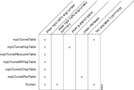
CLI Access to MPLS Traffic Engineering MIB Information
Figure 1 shows commands that you can use to retrieve information from specific tables in the MPLS TE MIB. As noted in this figure, some information in the MPLS TE MIB is not retrievable by commands.
Figure 1 Commands for Retrieving MPLS TE MIB Information
Retrieving Information from the MPLS Traffic Engineering MIB
This section describes how to efficiently retrieve information about TE tunnels. Such information can be useful in large networks that contain many TE tunnels.
Traverse across a single column of the mplsTunnelTable, such as mplsTunnelName. This action provides the indexes of every tunnel configuration, and any LSPs involving the host router. Using these indexes, you can perform a GET operation to retrieve information from any column and row of the mplsTunnelTable.
The mplsTunnelTable provides pointers to other tables for each tunnel. The column mplsTunnelResourcePointer, for example, provides an object ID (OID) that you can use to access resource allocation information in the mplsTunnelResourceTable. The columns mplsTunnelHopTableIndex, mplsTunnelARHopTableIndex, and mplsTunnelCHopTableIndex provide the primary index into the mplsTunnelHopTable, mplsTunnelARHopTable, and mplsTunnelCHopTable, respectively. By traversing the MPLS TE MIB in this manner using a hop table column and primary index, you can retrieve information pertaining to the hops of that tunnel configuration.
Because tunnels are treated as interfaces, the tunnel table column (mplsTunnelIfIndex) provides an index into the Interfaces MIB that you can use to retrieve interface-specific information about a tunnel.
How to Configure the MPLS Traffic Engineering MIB
This section contains the following tasks:
•
•
Enabling the SNMP Agent to Help Manage Various MPLS TE Tunnel Characteristics of Tunnels on the Local Router
The SNMP agent for the MPLS TE MIB is disabled by default. To enable the SNMP agent for the MPLS TE MIB, perform the following steps.
SUMMARY STEPS
1.
2.
3.
4.
5.
6.
7.
8.
DETAILED STEPS
Verifying the Status of the SNMP Agent
To verify that the SNMP agent has been enabled on a host network device, perform the following steps.
Step 1
Use this command to Telnet to the target device:
Router# telnet 192.172.172.172Step 2
Use this command to enable SNMP on the target device:
Router# enableStep 3
Use this command to display the running configuration on the target device and examine the output for displayed SNMP information.
Router# show running-config. . .snmp-server community public rosnmp-server community private roAny snmp-server statement that appears in the output and takes the form shown here verifies that SNMP has been enabled on that device.
Configuration Examples for the MPLS Traffic Engineering MIB
This section contains the following configuration examples:
Enabling the SNMP Agent to Help Manage Various MPLS TE Tunnel Characteristics of Tunnels on the Local Router: Example
The following example shows how to enable an SNMP agent on a host network device:
Router# configure terminalRouter(config)# snmp-server community snmp-community-stringThe following example shows how to enable SNMPv1 and SNMPv2C. The configuration permits any SNMP agent to access all MPLS TE MIB objects with read-only permissions using the community string public.
Router(config)# snmp-server community publicThe following example shows how to allow read-only access to all MPLS TE MIB objects relating to members of access list 4 that specify the comaccess community string. No other SNMP agents will have access to any MPLS TE MIB objects.
Router(config)# snmp-server community comaccess ro 4Additional References
The following sections provide references related to the MPLS Traffic Engineering MIB.
Related Documents
Standards
No new or modified standards are supported by this feature, and support for existing standards has not been modified by this feature.
—
MIBs
MPLS TE MIB
Interfaces MIB
To locate and download MIBs for selected platforms, Cisco IOS releases, and feature sets, use Cisco MIB Locator found at the following URL:
RFCs
Technical Assistance
Command Reference
This section documents modified commands only.
•
snmp-server community
To set up the community access string to permit access to the Simple Network Management Protocol (SNMP), use the snmp-server community command in global configuration mode. To remove the specified community string, use the no form of this command.
snmp-server community string [view view-name] [ro | rw] [ipv6 nacl] [access-list-number]
no snmp-server community string
Syntax Description
Command Default
An SNMP community string permits read-only access to all objects.
Note
Command Modes
Global configuration
Command History
Usage Guidelines
The no snmp-server command disables all versions of SNMP (SNMPv1, SNMPv2C, SNMPv3).
The first snmp-server command that you enter enables all versions of SNMP.
To configure SNMP community strings for the MPLS LDP MIB, use the snmp-server community command on the host network management station (NMS).
The snmp-server community command can be used to specify only an IPv6 named access list, only an IPv4 access list, or both. For you to configure both IPv4 and IPv6 access lists, the IPv6 access list must appear first in the command statement.
Note
Examples
The following example shows how to set the read/write community string to newstring:
Router(config)# snmp-server community newstring rwThe following example shows how to allow read-only access for all objects to members of the standard named access list lmnop that specify the comaccess community string. No other SNMP managers have access to any objects.
Router(config)# snmp-server community comaccess ro lmnopThe following example shows how to assign the string comaccess to SNMP, allow read-only access, and specify that IP access list 4 can use the community string:
Router(config)# snmp-server community comaccess ro 4The following example shows how to assign the string manager to SNMP and allow read-write access to the objects in the restricted view:
Router(config)# snmp-server community manager view restricted rwThe following example shows how to remove the community comaccess:
Router(config)# no snmp-server community comaccessThe following example shows how to disable all versions of SNMP:
Router(config)# no snmp-serverThe following example shows how to configure an IPv6 access list named list1 and links an SNMP community string with this access list:
Router(config)# ipv6 access-list list1Router(config-ipv6-acl)# permit ipv6 any anyRouter(config-ipv6-acl)# exitRouter(config)# snmp-server community comaccess rw ipv6 list1Related Commands
snmp-server enable traps (MPLS)
To enable a label switch router (LSR) to send Simple Network Management Protocol (SNMP) notifications or informs to an SNMP host, use the snmp-server enable traps command in global configuration mode. To disable notifications or informs, use the no form of this command.
snmp-server enable traps [notification-type] [notification-option]
no snmp-server enable traps [notification-type] [notification-option]
Syntax Description
Defaults
If you issue this command on an LSR without specifying any notification-type keywords, the default behavior of the LSR is to enable all notification types controlled by the command (some notification types cannot be controlled by means of this command).
Command Modes
Global configuration
Command History
Usage Guidelines
To configure an LSR to send SNMP LDP notifications, you must issue at least one snmp-server enable traps command on the router.
To configure an LSR to send either notifications (traps) or informs to a designated network management station (NMS), you must issue the snmp-server host command on that device, using the keyword (traps or informs) that suits your purposes.
If you issue the snmp-server enable traps command without keywords, all SNMP notification types are enabled on the LSR. If you issue this command with specific keywords, only the notification types associated with those particular keywords are enabled on the LSR.
The snmp-server enable traps command is used in conjunction with the snmp-server host command. You use the latter command to specify the NMS host (or hosts) targeted as the recipient(s) of the SNMP notifications generated by SNMP-enabled LSRs in the network. To enable an LSR to send such notifications, you must issue at least one snmp-server host command on the LSR.
Examples
In the following example, the router is enabled to send all notifications to the host specified as myhost.cisco.com. The community string is defined as public.
Router(config)# snmp-server enable trapsRouter(config)# snmp-server host myhost.cisco.com publicIn the following example, the router is enabled to send Frame Relay and environmental monitor notifications to the host specified as myhost.cisco.com. The community string is defined as public:
Router(config)# snmp-server enable traps frame-relayRouter(config)# snmp-server enable traps envmon temperatureRouter(config)# snmp-server host myhost.cisco.com publicIn the following example, notifications are not sent to any host. BGP notifications are enabled for all hosts, but the only notifications enabled to be sent to a host are ISDN notifications (which are not enabled in this example).
Router(config)# snmp-server enable traps bgpRouter(config)# snmp-server host host1 public isdnIn the following example, the router is enabled to send all inform requests to the host specified as myhost.cisco.com. The community string is defined as public.
Router(config)# snmp-server enable trapsRouter(config)# snmp-server host myhost.cisco.com informs version 2c publicIn the following example, HSRP MIB notifications are sent to the host specified as myhost.cisco.com. The community string is defined as public.
Router(config)# snmp-server enable hsrpRouter(config)# snmp-server host myhost.cisco.com traps version 2c public hsrpRelated Commands
snmp-server host
Specifies the intended recipient of an SNMP notification (that is, the designated NMS workstation in the network).
snmp-server host
To specify the recipient of a Simple Network Management Protocol (SNMP) notification message, use the snmp-server host command in global configuration mode. To remove the specified host from the configuration, use the no form of this command.
snmp-server host {hostname | ip-address} [vrf vrf-name] [traps | informs] [version {1 | 2c | 3 [auth | noauth | priv]}] community-string [udp-port port] [notification-type]
no snmp-server host {hostname | ip-address} [vrf vrf-name] [traps | informs] [version {1 | 2c | 3 [auth | noauth | priv]}] community-string [udp-port port] [notification-type]
Syntax Description
Command Default
The router does not send any trap messages.
If you enter the no snmp-server host command with no keywords, traps (but not informs) are disabled to the host. To disable informs, use the no snmp-server host informs command.
Note
Command Modes
Global configuration
Command History
Usage Guidelines
SNMP notifications can be sent as traps or inform requests. Traps are unreliable because the receiver does not send acknowledgments when it receives traps. The sender cannot determine if the traps were received. However, an SNMP entity that receives an inform request acknowledges the message with a SNMP response protocol data unit (PDU). If the sender never receives the response, the inform request can be sent again. Thus, informs are more likely to reach their intended destination.
Compared to traps, informs consume more resources in the agent and in the network. Unlike a trap, which is discarded as soon as it is sent, an inform request must be held in memory until a response is received or the request times out. Also, traps are sent only once; an inform may be retried several times. The retries increase traffic and contribute to a higher overhead on the network.
If you do not enter a snmp-server host command, no notifications are sent. To configure the router to send SNMP notifications, you must enter at least one snmp-server host command. If you enter the command with no keywords, all trap types are enabled for the host.
To enable multiple hosts, you must issue a separate snmp-server host command for each host. You can specify multiple notification types in the command for each host.
When multiple snmp-server host commands are given for the same host and kind of notification (trap or inform), each succeeding command overwrites the previous command. Only the last snmp-server host command will be in effect. For example, if you enter an snmp-server host informs command for a host and then enter another snmp-server host informs command for the same host, the second command will replace the first.
The snmp-server host command is used in conjunction with the snmp-server enable command. Use the snmp-server enable command to specify which SNMP notifications are sent globally. For a host to receive most notifications, at least one snmp-server enable command and the snmp-server host command for that host must be enabled.
Some notification types cannot be controlled with the snmp-server enable command. For example, some notification types are always enabled and others are enabled by a different command, and the linkUpDown notifications are controlled by the snmp trap link-status command. These notification types do not require an snmp-server enable command.
A notification-type option's availability depends on the router type and Cisco IOS software features supported on the router. For example, the envmon notification type is available only if the environmental monitor is part of the system. To display what notification types are available on your system, use the command help ? at the end of the snmp-server host command.
The vrf keyword allows you to specify the notifications being sent to a specified IP address over a specific VRF. The VRF defines a VPN membership of a customer so data is stored using the VPN.
Notification-Type Keywords
The notification-type keywords used in the snmp-server host command do not always match the keywords used in the corresponding snmp-server enable traps command. For example, the notification keyword applicable to MPLS traffic engineering tunnels is specified as mpls-traffic-eng (containing two hyphens and no intervening spaces). The corresponding parameter in the snmp-server enable traps command is specified as mpls-traffic-eng (containing an intervening space and a hyphen).
This syntax difference is necessary to ensure that the command-line interface (CLI) interprets the notification-type keyword of the snmp-server host command as a unified, single-word construct, which preserves the capability of the snmp-server host command to accept multiple notification-type keywords in the command line. The snmp-server enable traps commands, however, often use two-word constructs to provide hierarchical configuration options and to maintain consistency with the command syntax of related commands. Table 1 maps some examples of snmp-server enable traps commands to the keywords used in the snmp-server host command.
Table 1 Notification Keywords and Corresponding SNMP Enable Traps Commands
snmp-server enable traps l2tun session
l2tun-session
snmp-server enable traps mpls ldp
mpls-ldp
snmp-server enable traps mpls traffic-eng1
mpls-traffic-eng
snmp-server enable traps mpls vpn
mpls-vpn
1 See the Cisco IOS Multiprotocol Label Switching Command Reference for documentation of this command.
Examples
If you want to configure a unique SNMP community string for traps but prevent SNMP polling access with this string, include an access list in the configuration. The following example shows how to name a community string comaccess and number an access list 10:
Router(config)# snmp-server community comaccess ro 10Router(config)# snmp-server host 172.20.2.160 comaccessRouter(config)# access-list 10 deny any
Note
The following example shows how to send RFC 1157 SNMP traps to a host specified named myhost.cisco.com. Other traps are enabled, but only SNMP traps are sent because only snmp is specified in the snmp-server host command. The community string is defined as comaccess.
Router(config)# snmp-server enable trapsRouter(config)# snmp-server host myhost.cisco.com comaccess snmpThe following example shows how to send the SNMP and Cisco environmental monitor enterprise-specific traps to address 172.30.2.160 using the community string public:
Router(config)# snmp-server enable traps snmpRouter(config)# snmp-server enable traps envmonRouter(config)# snmp-server host 172.30.2.160 public snmp envmonThe following example shows how to enable the router to send all traps to the host myhost.cisco.com using the community string public:
Router(config)# snmp-server enable trapsRouter(config)# snmp-server host myhost.cisco.com publicThe following example will not send traps to any host. The BGP traps are enabled for all hosts, but only the ISDN traps are enabled to be sent to a host. The community string is defined as public.
Router(config)# snmp-server enable traps bgpRouter(config)# snmp-server host myhost.cisco.com public isdnThe following example shows how to enable the router to send all inform requests to the host myhost.cisco.com using the community string public:
Router(config)# snmp-server enable trapsRouter(config)# snmp-server host myhost.cisco.com informs version 2c publicThe following example shows how to send HSRP MIB informs to the host specified by the name myhost.cisco.com. The community string is defined as public.
Router(config)# snmp-server enable traps hsrpRouter(config)# snmp-server host myhost.cisco.com informs version 2c public hsrpThe following example shows how to send all SNMP notifications to example.com over the VRF named trap-vrf using the community string public:
Router(config)# snmp-server host example.com vrf trap-vrf publicThe following example shows how to configure an IPv6 SNMP notification server with the IPv6 address 2001:0DB8:0000:ABCD:1 using the community string public:
Router(config)# snmp-server host 2001:0DB8:0000:ABCD:1 version 2c public udp-port 2012The following example shows how to specify VRRP as the protocol using the community string public:
Router(config)# snmp-server enable traps vrrpRouter(config)# snmp-server host myhost.cisco.com traps version 2c public vrrpThe following example shows how to send all Cisco Express Forwarding informs to the notification receiver with the IP address 10.56.125.47 using the community string public.
Router(config)# snmp-server enable traps cefRouter(config)# snmp-server host 10.56.125.47 informs version 2c public cef
Feature Information for the MPLS Traffic Engineering MIB
Table 2 lists the release history for this MIB.
Not all commands may be available in your Cisco IOS software release. For release information about a specific command, see the command reference documentation.
Use Cisco Feature Navigator to find information about platform support and software image support. Cisco Feature Navigator enables you to determine which Cisco IOS and Catalyst OS software images support a specific software release, feature set, or platform. To access Cisco Feature Navigator, go to http://www.cisco.com/go/cfn. An account on Cisco.com is not required.
Note
Glossary
affinity bits—An MPLS traffic engineering tunnel's requirements on the attributes of the links it will cross. The tunnel's affinity bits and affinity mask must match with the attributes of the various links carrying the tunnel.
call admission precedence—An MPLS traffic engineering tunnel with a higher priority will, if necessary, preempt an MPLS traffic engineering tunnel with a lower priority. An expected use is that tunnels that are harder to route will have a higher priority, and can preempt tunnels that are easier to route, on the assumption that those lower priority tunnels can find another path.
constraint-based routing—Procedures and protocols used to determine a route across a backbone taking into account resource requirements and resource availability, instead of simply using the shortest path.
flow—A traffic load entering the backbone at one point—point of presence (POP)—and leaving it from another that must be traffic engineered across the backbone. The traffic load will be carried across one or more LSP tunnels running from the entry POP to the exit POP.
headend—The LSR at which the tunnel originates. The tunnel's "head" or tunnel interface will reside at this LSR as well.
informs—A type of notification message that is more reliable than a conventional trap notification message because an informs message requires acknowledgment.
label—A short, fixed-length data construct that tells switching nodes how to forward data (packets or cells).
label-switched path (LSP) tunnel—A configured connection between two routers, using label switching to carry the packets.
LSP—label-switched path. A path that is followed by a labeled packet over several hops, starting at an ingress LSR and ending at an egress LSR.
LSR—label switch router. A Layer 3 router that forwards a packet based on the value of a label encapsulated in the packet.
MIB—Management Information Base. A database of network management information (consisting of MIB objects) that is used and maintained by a network management protocol such as SNMP. The value of a MIB object can be changed or retrieved using SNMP commands, usually by a GUI-based network management system. MIB objects are organized in a tree structure that includes public (standard) and private (proprietary) branches.
MPLS—Multiprotocol Label Switching. Switching method that forwards IP traffic using a label. This label instructs the routers and the switches in the network where to forward the packets based on preestablished IP routing information.
notification (see traps)—A message sent by an SNMP agent to a network management station, console, or terminal to indicate that a significant event within Cisco IOS software has occurred.
NMS—network management station. An NMS is a powerful, well-equipped computer (typically an engineering workstation) that is used by a network administrator to communicate with other devices in the network. An NMS is typically used to manage network resources, gather statistics, and perform a variety of network administration and configuration tasks.
OSPF—Open Shortest Path First. A link-state routing protocol used for routing IP.
RSVP—Resource Reservation Protocol. Protocol for reserving network resources to provide quality of service (QoS) guarantees to application flows.
SNMP—Simple Network Management Protocol. A network management protocol used almost exclusively in TCP/IP networks. SNMP provides a means to monitor and control network devices, manage configurations, collect statistics, monitor performance, and ensure network security.
tailend—The downstream, receive end of a tunnel.
traffic engineering—Techniques and processes that cause routed traffic to travel through the network on a path other than the one that would have been chosen if standard routing methods were used.
trap (see notification)—A message sent by an SNMP agent to a network management station, console, or terminal to indicate that a significant event within Cisco IOS software has occurred. Traps (notifications) are less reliable than inform requests, because the receiver of the trap does not send an acknowledgment of receipt; furthermore, the sender of the trap cannot determine if the trap was received.
VCI—virtual channel identifier. A 16-bit field in the header of an ATM cell. The VCI, together with the VPI, is used to identify the next network VCL as the cell passes through a series of ATM switches on its way to its final destination.
VCC—virtual channel connection. A VCC is a logical circuit consisting of VCLs that carries data between two endpoints in an ATM network. Sometimes called a virtual circuit connection.
VCL—virtual channel link. A VCL is the logical connection that exists between two adjacent switches in an ATM network.
VPI—virtual path identifier. An 8-bit field in the header of an ATM cell. The VPI, together with the VCI, is used to identify the next network VCL (see above) as the cell passes through a series of ATM switches on its way to its final destination.
Note
Any Internet Protocol (IP) addresses used in this document are not intended to be actual addresses. Any examples, command display output, and figures included in the document are shown for illustrative purposes only. Any use of actual IP addresses in illustrative content is unintentional and coincidental.
© 2002, 2006 Cisco Systems, Inc. All rights reserved.