Downloads |
 Feedback Feedback
|
Table Of Contents
Prerequisites for NSF/SSO—MPLS VPN
Restrictions for NSF/SSO—MPLS VPN
Information About NSF/SSO—MPLS VPN
Elements That Enable NSF/SSO—MPLS VPN to Work
How VPN Prefix Information Is Checkpointed to the Backup Route Processor
How BGP Graceful Restart Preserves Prefix Information During a Restart
What Happens If a Router Does Not Have NSF/SSO—MPLS VPN Enabled
How to Configure NSF/SSO—MPLS VPN
Configuring NSF Support for Basic VPNs
Configuring NSF Support for MPLS VPN Interfaces That Use BGP as the Label Distribution Protocol
Verifying the NSF/SSO—MPLS VPN Configuration
Configuration Examples for NSF/SSO—MPLS VPN
NSF/SSO—MPLS VPN for a Basic MPLS VPN: Example
NSF/SSO—MPLS VPN for a CSC Network with a Customer Carrier Who Is an ISP: Example
NSF/SSO—MPLS VPN for a CSC Network with a Customer Who Is an MPLS VPN Provider: Example
NSF/SSO—MPLS VPN for a CSC Network That Uses BGP to Distribute MPLS Labels: Example
NSF/SSO—MPLS VPN for an Inter-AS Network Using BGP to Distribute Routes and MPLS Labels: Example
Feature Information for NSF/SSO—MPLS VPN
NSF/SSO—MPLS VPN
First Published: August 11, 2004Last Updated: August 21, 2007The NSF/SSO—MPLS VPN feature allows a provider edge (PE) router or Autonomous System Border Router (ASBR) (with redundant Route Processors) to preserve data forwarding information in a Multiprotocol Label Switching (MPLS) Virtual Private Network (VPN) when the primary Route Processor (RP) restarts. This feature module describes how to enable Nonstop Forwarding in MPLS VPN networks, including the following types of VPNs:
•
Basic MPLS VPNs
•
•
•
•
Finding Feature Information in This Module
Your Cisco IOS software release may not support all of the features documented in this module. To reach links to specific feature documentation in this module and to see a list of the releases in which each feature is supported, use the "Feature Information for NSF/SSO—MPLS VPN" section.
Finding Support Information for Platforms and Cisco IOS and Catalyst OS Software Images
Use Cisco Feature Navigator to find information about platform support and Cisco IOS and Catalyst OS software image support. To access Cisco Feature Navigator, go to http://www.cisco.com/go/cfn. An account on Cisco.com is not required.
Contents
•
•
•
•
•
•
Prerequisites for NSF/SSO—MPLS VPN
The NSF/SSO—MPLS VPN feature has the following prerequisites:
For information about supported hardware, see the following documents:
•
•
•
•
–
Before enabling Stateful Switchover (SSO), you must enable MPLS Label Distrbution Protocol (LDP) Graceful Restart if you use LDP in the core or in the MPLS VPN routing and forwarding instance in an MPLS VPN Carrier Supporting Carrier configuration. See the NSF/SSO-MPLS LDP and MPLS LDP Graceful Restart feature module for more information.
You must enable NSF on the routing protocols running between the provider (P) routers , PE routers, and customer edge (CE) routers. The routing protocols are:
•
•
•
Cisco nonstop forwarding support must be configured on the routers for Cisco Express Forwarding. See the Cisco Nonstop Forwarding feature module for more information.
Before enabling the NSF/SSO—MPLS VPN feature, you must have a supported MPLS VPN network configuration. Configuration information is included in the "Part 4: MPLS Virtual Private Networks" module in the Cisco IOS Multiprotocol Label Switching Configuration Guide, Release 12.4.
Restrictions for NSF/SSO—MPLS VPN
The NSF/SSO—MPLS VPN feature has the following restrictions:
•
•
•
Information About NSF/SSO—MPLS VPN
To configure NSF/SSO—MPLS VPN, you need to understand the following concepts:
•
•
•
•
Elements That Enable NSF/SSO—MPLS VPN to Work
VPN NSF requires several elements to work:
•
•
•
•
How VPN Prefix Information Is Checkpointed to the Backup Route Processor
When BGP allocates local labels for prefixes, it checkpoints the local label binding in the backup Route Processor. The checkpointing function copies state information from the active Route Processor to the backup Route Processor, thereby ensuring that the backup Route Processor has an identical copy of the latest information. If the active Route Processor fails, the backup Route Processor can take over with no interruption in service. Checkpointing begins when the active Route Processor does a bulk synchronization, which copies all of the local label bindings to the backup Route Processor. After that, the active Route Processor dynamically checkpoints individual prefix label bindings when a label is allocated or freed. This allows forwarding of labeled packets to continue before BGP reconverges.
How BGP Graceful Restart Preserves Prefix Information During a Restart
When a router that is capable of BGP Graceful Restart loses connectivity, the following happens to the restarting router:
1.
2.
3.
When a peer router that is capable of BGP Graceful Restart encounters a restarting router, it does the following:
1.
2.
What Happens If a Router Does Not Have NSF/SSO—MPLS VPN Enabled
If a router is not configured for the NSF/SSO—MPLS VPN feature and it attempts to establish a BGP session with a router that is configured with the NSF/SSO—MPLS VPN feature, the two routers create a normal BGP session but do not have the ability to perform the NSF/SSO—MPLS VPN feature.
How to Configure NSF/SSO—MPLS VPN
This section contains the following procedures:
•
•
•
Configuring NSF Support for Basic VPNs
Perform this task to configure NSF support for basic VPNs.
Prerequisites
Route Processors must be configured for SSO. See the Stateful Switchover feature module for more information.
If you use LDP in the core or in the virtual routing and forwarding (VRF) instances for MPLS VPN Carrier Supporting Carrier configurations, you must enable the MPLS LDP: NSF/SSO Support and Graceful Restart feature. See the NSF/SSO-MPLS LDP and MPLS LDP Graceful Restart feature module for more information.
You must enable Nonstop Forwarding on the routing protocols running between the P, PE, and CE routers. The routing protocols are OSPF, IS-IS, and BGP. See the Cisco Nonstop Forwarding feature module for more information.
Before enabling the NSF/SSO—MPLS VPN feature, you must have a supported MPLS VPN network configuration. Configuration information is included in the "Part 4: MPLS Virtual Private Networks" module in the Cisco IOS Multiprotocol Label Switching Configuration Guide, Release 12.4, at the following URL:
SUMMARY STEPS
1.
2.
3.
4.
5.
6.
7.
8.
DETAILED STEPS
Step 1
enable
Example:Router> enable
Enables privileged EXEC mode.
•
Step 2
configure terminal
Example:Router# configure terminal
Enters global configuration mode.
Step 3
ip cef [distributed]
Example:Router(config)# ip cef distributed
Enables Cisco Express Forwarding
•
Step 4
router bgp as-number
Example:Router(config)# router bgp 1
Configures a BGP routing process and enters router configuration mode.
•
Valid numbers are from 0 to 65535. Private autonomous system numbers that can be used in internal networks range from 64512 to 65535.
Step 5
bgp graceful-restart restart-time secsExample:Router(config-router)# bgp graceful-restart restart-time 200(Optional) Specifies the maximum time to wait for a graceful-restart-capable neighbor to come back up after a restart. The default is 120 seconds. The valid range is from 1 to 3600 seconds.
Step 6
bgp graceful-restart stalepath-time secsExample:Router(config-router)# bgp graceful-restart stalepath-time 400(Optional) Specifies the maximum time to hold on to the stale paths of a gracefully restarted peer. All stale paths are deleted after the expiration of this timer. The default is 360 seconds. The valid range is from 1 to 3600 seconds.
Step 7
Enables BGP Graceful Restart on the router. See Cisco Nonstop Forwarding for more information about the bgp graceful-restart command.
Step 8
end
Example:Router(config-router)# end
(Optional) Exits to privileged EXEC mode.
Configuring NSF Support for MPLS VPN Interfaces That Use BGP as the Label Distribution Protocol
The following VPN features require special configuration for the NSF/SSO—MPLS VPN feature:
•
•
You must issue an extra command, mpls forwarding bgp, on the interfaces that use BGP to distribute MPLS labels and routes. Use the following procedure to configure the NSF/SSO—MPLS VPN feature in these MPLS VPNs.
Prerequisites
•
•
SUMMARY STEPS
1.
2.
3.
4.
5.
DETAILED STEPS
Verifying the NSF/SSO—MPLS VPN Configuration
This section explains how to verify a configuratin that has the the NSF/SSO—MPLS VPN feature.
•
•
•
SUMMARY STEPS
1.
2.
3.
4.
DETAILED STEPS
Step 1
This command displays incoming and outgoing BGP labels for each route distinguisher. The following is sample output from the command:
Router# show ip bgp vpnv4 all labelsNetwork Next Hop In label/Out labelRoute Distinguisher: 100:1 (vpn1)10.3.0.0/16 10.0.0.5 25/2010.0.0.1 25/2310.0.0.2 25/imp-null10.0.0.9/32 10.0.0.1 24/2210.0.0.2 24/imp-nullStep 2
This command displays whether the BGP peers are capable of Graceful Restart. The following is sample output from the command:
Router# show ip bgp vpnv4 all neighborsBGP neighbor is 10.0.0.1, remote AS 100, internal linkBGP version 4, remote router ID 10.0.0.1BGP state = Established, up for 02:49:47Last read 00:00:47, hold time is 180, keepalive interval is 60 secondsNeighbor capabilities:Route refresh: advertised and received(new)Address family VPNv4 Unicast: advertised and receivedGraceful Restart Capabilty: advertised and receivedRemote Restart timer is 120 secondsAddress families preserved by peer:VPNv4 Unicast...Step 3
This command displays information about MPLS labels in the Exterior Border Gateway Protocol (EBGP) route table. The following is sample output from the command:
Router# show ip bgp labelsNetwork Next Hop In label/Out label10.3.0.0/16 10.0.0.1 imp-null/imp-null0.0.0.0 imp-null/nolabel10.0.0.9/32 10.0.0.1 21/2910.0.0.11/32 10.0.0.1 24/3810.0.0.13/32 0.0.0.0 imp-null/nolabel10.0.0.15/32 10.0.0.1 29/nolabel10.0.0.1 29/21Step 4
This command displays whether the BGP peers are capable of Graceful Restart. The following is sample output from the command:
Router# show ip bgp neighborsBGP neighbor is 10.0.0.1, remote AS 100, external linkBGP version 4, remote router ID 10.0.0.5BGP state = Established, up for 02:54:19Last read 00:00:18, hold time is 180, keepalive interval is 60 secondsNeighbor capabilities:Route refresh: advertised and received(new)Address family IPv4 Unicast: advertised and receivedipv4 MPLS Label capability: advertised and receivedGraceful Restart Capabilty: advertised and receivedRemote Restart timer is 120 secondsAddress families preserved by peer:IPv4 Unicast...Configuration Examples for NSF/SSO—MPLS VPN
This section includes six configuration examples. The first configuration example shows the most simple configuration, a basic VPN configuration. The second, third, and fourth examples show different CSC VPN configurations. The fourth example hows a CSC VPN configuration that uses BGP as the MPLS label distribution method and therefore requires the mpls forwarding bgp command. The last two examples show Inter-AS configurations.
•
•
•
•
•
NSF/SSO—MPLS VPN for a Basic MPLS VPN: Example
In this example, the NSF/SSO—MPLS VPN feature is enabled on the existing MPLS VPN configuration.
Enabling SSO on a Cisco 7500 Series Router
The following commands are used to enable SSO on the Cisco 7500 series routers:
•
•
•
The configuration examples are the same for both platforms with the exception that the following configuration boot commands are seen in the beginning of a Cisco 7500 series router configuration (and not in a Cisco 10000 series router configuration):
boot system slot0:rsp-pv-mzhw-module slot 2 image slot0:rsp-pv-mzhw-module slot 3 image slot0:rsp-pv-mzEnabling SSO on a Cisco 10000 Series Router
The SSO mode is enabled by default.
Enabling NSF on Both the Cisco 7500 Series and Cisco 10000 Series Routers
The following commands are used to enable NSF for the routing protocols, such as BGP and OSPF, and for the label distribution protocols, such as BGP and LDP:
•
•
•
•
Note
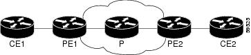
Figure 1 shows the configuration of the NSF/SSO—MPLS VPN feature on the PE and CE routers.
Figure 1 MPLS VPN Configuration with MPLS VPN: NSF/SSO
Note
The following configuration examples show the configuration of the NSF/SSO—MPLS VPN feature on the CE and PE routers.
CE1 Router
ip cefno ip domain-lookup!interface Loopback0ip address 10.10.10.10 255.255.255.255!interface Ethernet4ip address 10.0.0.1 255.0.0.0media-type 10BaseT!router ospf 100redistribute bgp 101nsf enforce globalpassive-interface Ethernet4network 10.0.0.0 0.255.255.255 area 100!router bgp 101no synchronizationbgp graceful-restart restart-time 120bgp graceful-restart stalepath-time 360bgp graceful-restart network 10.0.0.0network 10.0.0.0neighbor 10.0.0.2 remote-as 100PE1 Router
redundancymode sso!ip cef distributedmpls ldp graceful-restartmpls label protocol ldpip vrf vpn1rd 100:1route-target export 100:1route-target import 100:1no mpls aggregate-statistics!interface Loopback0ip address 10.12.12.12 255.255.255.255!interface Ethernet1/4 =====> interface FastEthernet1/1/4 on a Cisco 10000 series routerip vrf forwarding vpn1ip address 10.0.0.2 255.0.0.0!mpls ipinterface ATM3/0 =====> interface ATM3/0/0 on a Cisco 10000 series routerno ip address!interface ATM3/0.1 point-to-point ==> interface ATM3/0/0.1 point-to-point on a Cisco 10000ip unnumbered Loopback0mpls ip!router ospf 100passive-interface Ethernet1/4 ===> passive-interface FastEthernet1/1/4 on a Cisco 10000nsf enforce globalnetwork 10.0.0.0 0.255.255.255 area 100!router bgp 100no synchronizationbgp graceful-restart restart-time 120bgp graceful-restart stalepath-time 360bgp graceful-restartno bgp default ipv4-unicastneighbor 10.14.14.14 remote-as 100neighbor 10.14.14.14 update-source Loopback0!address-family ipv4 vrf vpn1neighbor 10.0.0.1 remote-as 101neighbor 10.0.0.1 activateexit-address-family!address-family vpnv4neighbor 10.14.14.14 activateneighbor 10.14.14.14 send-community extendedexit-address-familyPE2 Router
redundancymode sso!ip cef distributedmpls ldp graceful-restartmpls label protocol ldp!ip vrf vpn1rd 100:1route-target export 100:1route-target import 100:1no mpls aggregate-statistics!!interface Loopback0ip address 10.14.14.14 255.255.255.255!interface ATM1/0 =====> interface ATM1/0/0 on a Cisco 10000 series routerno ip address!interface ATM1/0.1 point-to-point ==> interface ATM1/0/0.1 point-to-point on a Cisco 10000ip unnumbered Loopback0mpls ip!interface FastEthernet3/0/0ip vrf forwarding vpn1ip address 10.0.0.1 255.0.0.0ip route-cache distributedmpls ip!router ospf 100nsf enforce globalpassive-interface FastEthernet3/0/0network 10.0.0.0 0.255.255.255 area 100!router bgp 100no synchronizationbgp graceful-restart restart-time 120bgp graceful-restart stalepath-time 360bgp graceful-restartno bgp default ipv4-unicastneighbor 10.12.12.12 remote-as 100neighbor 10.12.12.12 update-source Loopback0!address-family ipv4 vrf vpn1neighbor 10.0.0.2 remote-as 102neighbor 10.0.0.2 activateexit-address-family!address-family vpnv4neighbor 10.12.12.12 activateneighbor 10.12.12.12 send-community extendedexit-address-familyCE2 Router
ip cef!interface Loopback0ip address 10.13.13.13 255.255.255.255!interface FastEthernet0ip address 10.0.0.2 255.0.0.0no ip mroute-cache!router ospf 100redistribute bgp 102nsf enforce globalpassive-interface FastEthernet0network 10.0.0.0 0.255.255.255 area 100!router bgp 102no synchronizationbgp graceful-restart restart-time 120bgp graceful-restart stalepath-time 360bgp graceful-restartnetwork 10.0.0.0network 10.0.0.0neighbor 10.0.0.1 remote-as 100NSF/SSO—MPLS VPN for a CSC Network with a Customer Carrier Who Is an ISP: Example
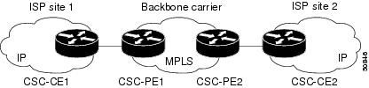
In this example, MPLS VPN SSO and NSF are configured on the existing MPLS CSC VPN configuration. In the CSC network configuration, the customer carrier is an Internet Service Provider (ISP), as shown in Figure 2.
Enabling SSO on a Cisco 7500 Series Router
The following commands are used to enable SSO on the Cisco 7500 series routers:
•
•
•
The configuration examples are the same for both platforms with the exception that the following configuration boot commands are seen in the beginning of a Cisco 7500 series router configuration (and not in a Cisco 10000 series router configuration):
boot system slot0:rsp-pv-mzhw-module slot 2 image slot0:rsp-pv-mzhw-module slot 3 image slot0:rsp-pv-mzEnabling SSO on a Cisco 10000 Series Router
The SSO mode is enabled by default.
Enabling NSF on Both the Cisco 7500 Series and Cisco 10000 Series Routers
The following commands are used to enable NSF for the routing protocols, such as BGP and OSPF, and for the label distribution protocols, such as BGP and LDP:
•
•
•
•
Note
Figure 2 MPLS VPN CSC Configuration with MPLS VPN: NSF and SSO
CSC-CE1 Configuration
mpls ldp graceful-restartmpls label protocol ldp!interface Loopback0ip address 10.14.14.14 255.255.255.255!no ip route-cacheno ip mroute-cache!interface ATM1/0no ip address!interface ATM1/0.1 point-to-pointip address 10.0.0.2 255.0.0.0!atm pvc 101 0 51 aal5snapno atm enable-ilmi-trapmpls label protocol ldpmpls ip!interface ATM2/0no ip address!interface ATM2/0.1 point-to-pointip address 10.0.0.2 255.0.0.0!atm pvc 100 0 50 aal5snapno atm enable-ilmi-trapmpls label protocol ldpmpls ip!router ospf 200log-adjacency-changesredistribute connected subnetsnsf enforce globalnetwork 10.14.14.14 0.0.0.0 area 200network 10.0.0.0 0.255.255.255 area 200network 10.0.0.0 0.255.255.255 area 200CSC-PE1 Configuration
redundancymode ssoip cef distributedmpls ldp graceful-restartmpls label protocol ldp!ip vrf vpn1rd 100:0route-target export 100:0route-target import 100:0no mpls aggregate-statistics!interface Loopback0ip address 10.11.11.11 255.255.255.255!no ip route-cacheno ip mroute-cache!interface Loopback100ip vrf forwarding vpn1ip address 10.19.19.19 255.255.255.255!interface ATM1/1/0no ip address!interface ATM1/1/0.1 point-to-pointip address 10.0.0.1 255.0.0.0!atm pvc 100 0 50 aal5snapno atm enable-ilmi-trapmpls label protocol ldpmpls ip!interface ATM3/0/0no ip address!interface ATM3/0/0.1 point-to-pointip vrf forwarding vpn1ip address 10.0.0.1 255.0.0.0atm pvc 101 0 51 aal5snapno atm enable-ilmi-trapmpls label protocol ldpmpls ip!router ospf 100log-adjacency-changesnsf enforce globalpassive-interface ATM3/0/0.1passive-interface Loopback100network 10.11.11.11 0.0.0.0 area 100network 10.0.0.0 0.255.255.255 area 100!router ospf 200 vrf vpn1log-adjacency-changesnsf enforce globalredistribute bgp 100 metric-type 1 subnetsnetwork 10.19.19.19 0.0.0.0 area 200network 10.0.0.0 0.255.255.255 area 200!router bgp 100bgp log-neighbor-changesbgp graceful-restart restart-time 120bgp graceful-restart stalepath-time 360bgp graceful-restarttimers bgp 10 30neighbor 10.12.12.12 remote-as 100neighbor 10.12.12.12 update-source Loopback0!address-family ipv4neighbor 10.12.12.12 activateneighbor 10.12.12.12 send-community extendedno synchronizationexit-address-family!address-family vpnv4neighbor 10.12.12.12 activateneighbor 10.12.12.12 send-community extendedexit-address-family!address-family ipv4 vrf vpn1redistribute ospf 200 match internal external 1 external 2no auto-summaryno synchronizationexit-address-familyCSC-PE2 Configuration
redundancymode ssoip cef distributed!ip vrf vpn1rd 100:0route-target export 100:0route-target import 100:0mpls ldp graceful-restartmpls label protocol ldpno mpls aggregate-statistics!interface Loopback0ip address 10.12.12.12 255.255.255.255no ip route-cacheno ip mroute-cache!interface Loopback100ip vrf forwarding vpn1ip address 10.20.20.20 255.255.255.255!interface ATM0/1/0no ip address!interface ATM0/1/0.1 point-to-pointip address 10.0.0.2 255.0.0.0atm pvc 100 0 50 aal5snapno atm enable-ilmi-trapmpls label protocol ldpmpls ip!interface ATM3/0/0no ip address!interface ATM3/0/0.1 point-to-pointip vrf forwarding vpn1ip address 10.0.0.1 255.0.0.0atm pvc 100 0 50 aal5snapno atm enable-ilmi-trapmpls label protocol ldpmpls ip!router ospf 100log-adjacency-changesnsf enforce globalpassive-interface ATM3/0/0.1passive-interface Loopback100network 10.12.12.12 0.0.0.0 area 100network 10.0.0.0 0.255.255.255 area 100!router ospf 200 vrf vpn1log-adjacency-changesnsf enforce globalredistribute bgp 100 metric-type 1 subnetsnetwork 10.20.20.20 0.0.0.0 area 200network 10.0.0.0 0.255.255.255 area 200!router bgp 100bgp log-neighbor-changesbgp graceful-restart restart-time 120bgp graceful-restart stalepath-time 360bgp graceful-restarttimers bgp 10 30neighbor 10.11.11.11 remote-as 100neighbor 10.11.11.11 update-source Loopback0!address-family ipv4neighbor 10.11.11.11 activateneighbor 10.11.11.11 send-community extendedno synchronizationexit-address-family!address-family vpnv4neighbor 10.11.11.11 activateneighbor 10.11.11.11 send-community extendedexit-address-family!address-family ipv4 vrf vpn1redistribute ospf 200 match internal external 1 external 2no auto-summaryno synchronizationexit-address-familyCSC-CE2 Configuration
ip cef!mpls label protocol ldpmpls ldp graceful-restart!interface Loopback0ip address 10.16.16.16 255.255.255.255no ip route-cacheno ip mroute-cache!interface ATM1/0no ip address!interface ATM1/0.1 point-to-pointip address 10.0.0.2 255.0.0.0atm pvc 100 0 50 aal5snapno atm enable-ilmi-trapmpls label protocol ldpmpls ip!interface ATM5/0no ip address!interface ATM5/0.1 point-to-pointip address 10.0.0.2 255.0.0.0atm pvc 100 0 50 aal5snapno atm enable-ilmi-trapmpls label protocol ldpmpls ip!router ospf 200log-adjacency-changesnsf enforce globalredistribute connected subnetsnetwork 10.16.16.16 0.0.0.0 area 200network 10.0.0.0 0.255.255.255 area 200network 10.0.0.0 0.255.255.255 area 200NSF/SSO—MPLS VPN for a CSC Network with a Customer Who Is an MPLS VPN Provider: Example
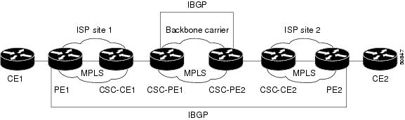
In the CSC network configuration shown in Figure 3, the customer carrier is an MPLS VPN provider. The customer carrier has two sites. The backbone carrier and the customer carrier use MPLS. The internal BGP (iBGP) sessions exchange the external routing information of the ISP.
Figure 3 MPLS VPN CSC Configuration 2 with MPLS VPN: NSF and SSO
The following configuration example shows the configuration of each router in the CSC network. OSPF is the protocol used to connect the customer carrier to the backbone carrier. The NSF/SSO—MPLS VPN feature is enabled on the existing MPLS VPN configuration.
Enabling SSO on a Cisco 7500 Series Router
The following commands are used to enable SSO on the routers:
•
•
•
The configuration examples are the same for both platforms with the exception that the following configuration boot commands are seen in the beginning of a Cisco 7500 series router configuration (and not in a Cisco 10000 series router configuration):
boot system slot0:rsp-pv-mzhw-module slot 2 image slot0:rsp-pv-mzhw-module slot 3 image slot0:rsp-pv-mzEnabling SSO on a Cisco 10000 Series Router
The SSO mode is enabled by default.
Enabling NSF on Both the Cisco 7500 Series and Cisco 10000 Series Routers
The following commands are used to enable NSF for the routing protocols, such as BGP and OSPF, and for the label distribution protocols, such as BGP and LDP:
•
•
•
•
Note
CE1 Configuration
ip cef!interface Loopback0ip address 10.17.17.17 255.255.255.255!interface Ethernet0/1ip address 10.0.0.2 255.0.0.0!router ospf 300log-adjacency-changesnsf enforce globalredistribute bgp 300 subnetspassive-interface Ethernet0/1network 10.17.17.17 0.0.0.0 area 300!router bgp 300no synchronizationbgp log-neighbor-changesbgp graceful-restart restart-time 120bgp graceful-restart stalepath-time 360bgp graceful-restarttimers bgp 10 30redistribute connectedredistribute ospf 300 match internal external 1 external 2neighbor 10.0.0.1 remote-as 200neighbor 10.0.0.1 advertisement-interval 5no auto-summaryPE1 Configuration
redundancymode ssoip cef distributedmpls ldp graceful-restartmpls label protocol ldp!ip vrf vpn2rd 200:1route-target export 200:1route-target import 200:1!interface Loopback0ip address 10.13.13.13 255.255.255.255!interface ATM1/0 =====> interface ATM1/0/0 on a Cisco 10000 series routerno ip address!interface ATM1/0.1 point-to-point ===> interface ATM1/0/0 point-to-point on a Cisco 10000ip address 10.0.0.1 255.0.0.0atm pvc 100 0 50 aal5snapno atm enable-ilmi-trapmpls label protocol ldpmpls ip!interface Ethernet3/0 =====> interface FastEthernet3/0/0 on a Cisco 10000 series routerip vrf forwarding vpn2ip address 10.0.0.1 255.0.0.0no ip mroute-cache!router ospf 200log-adjacency-changesredistribute connected subnetsnsf enforce globalpassive-interface Ethernet3/0 ===> passive-interface FastEthernet3/0/0 on a Cisco 10000network 10.13.13.13 0.0.0.0 area 200network 10.0.0.0 0.255.255.255 area 200!router bgp 200no bgp default ipv4-unicastbgp log-neighbor-changesbgp graceful-restart restart-time 120bgp graceful-restart stalepath-time 360bgp graceful-restarttimers bgp 10 30neighbor 10.15.15.15 remote-as 200neighbor 10.15.15.15 update-source Loopback0!address-family ipv4neighbor 10.15.15.15 activateneighbor 10.15.15.15 send-community extendedno synchronizationexit-address-family!address-family vpnv4neighbor 10.15.15.15 activateneighbor 10.15.15.15 send-community extendedexit-address-family!address-family ipv4 vrf vpn2neighbor 10.0.0.2 remote-as 300neighbor 10.0.0.2 activateneighbor 10.0.0.2 as-overrideneighbor 10.0.0.2 advertisement-interval 5no auto-summaryno synchronizationexit-address-familyCSC-CE1 Configuration
mpls label protocol ldpmpls ldp graceful-restart!interface Loopback0ip address 10.14.14.14 255.255.255.255no ip route-cacheno ip mroute-cache!interface ATM1/0no ip address!interface ATM1/0.1 point-to-pointip address 10.0.0.2 255.0.0.0atm pvc 101 0 51 aal5snapno atm enable-ilmi-trapmpls label protocol ldpmpls ip!interface ATM2/0no ip address!interface ATM2/0.1 point-to-pointip address 10.0.0.2 255.0.0.0atm pvc 100 0 50 aal5snapno atm enable-ilmi-trapmpls label protocol ldpmpls ip!router ospf 200log-adjacency-changesredistribute connected subnetsnsf enforce globalnetwork 10.14.14.14 0.0.0.0 area 200network 10.0.0.0 0.255.255.255 area 200network 10.0.0.0 0.255.255.255 area 200CSC-PE1 Configuration
redundancymode ssoip cef distributed!ip vrf vpn1rd 100:0route-target export 100:0route-target import 100:0mpls label protocol ldpmpls ldp graceful-restartno mpls aggregate-statistics!interface Loopback0ip address 10.11.11.11 255.255.255.255no ip route-cacheno ip mroute-cache!interface Loopback100ip vrf forwarding vpn1ip address 10.19.19.19 255.255.255.255!interface ATM1/1/0no ip address!interface ATM1/1/0.1 point-to-pointip address 10.0.0.1 255.0.0.0atm pvc 100 0 50 aal5snapno atm enable-ilmi-trapmpls label protocol ldpmpls ip!interface ATM3/0/0no ip address!interface ATM3/0/0.1 point-to-pointip vrf forwarding vpn1ip address 10.0.0.1 255.0.0.0atm pvc 101 0 51 aal5snapno atm enable-ilmi-trapmpls label protocol ldpmpls ip!router ospf 100log-adjacency-changespassive-interface ATM3/0/0.1nsf enforce globalpassive-interface Loopback100network 10.11.11.11 0.0.0.0 area 100network 10.0.0.0 0.255.255.255 area 100!router ospf 200 vrf vpn1log-adjacency-changesnsf enforce globalredistribute bgp 100 metric-type 1 subnetsnetwork 10.19.19.19 0.0.0.0 area 200network 10.0.0.0 0.255.255.255 area 200!router bgp 100bgp log-neighbor-changestimers bgp 10 30bgp graceful-restart restart-time 120bgp graceful-restart stalepath-time 360bgp graceful-restartneighbor 10.12.12.12 remote-as 100neighbor 10.12.12.12 update-source Loopback0!address-family ipv4neighbor 10.12.12.12 activateneighbor 10.12.12.12 send-community extendedno synchronizationexit-address-family!address-family vpnv4neighbor 10.12.12.12 activateneighbor 10.12.12.12 send-community extendedexit-address-family!address-family ipv4 vrf vpn1redistribute ospf 200 match internal external 1 external 2no auto-summaryno synchronizationexit-address-familyCSC-PE2 Configuration
redundancymode ssoip cef distributed!ip vrf vpn1rd 100:0route-target export 100:0route-target import 100:0mpls label protocol ldpmpls ldp graceful-restartno mpls aggregate-statistics!interface Loopback0ip address 10.12.12.12 255.255.255.255no ip route-cacheno ip mroute-cache!interface Loopback100ip vrf forwarding vpn1ip address 10.20.20.20 255.255.255.255!interface ATM0/1/0no ip address!interface ATM0/1/0.1 point-to-pointip address 10.0.0.2 255.0.0.0atm pvc 100 0 50 aal5snapno atm enable-ilmi-trapmpls label protocol ldpmpls ip!interface ATM3/0/0no ip address!interface ATM3/0/0.1 point-to-pointip vrf forwarding vpn1ip address 10.0.0.1 255.0.0.0atm pvc 100 0 50 aal5snapno atm enable-ilmi-trapmpls label protocol ldpmpls ip!router ospf 100log-adjacency-changesnsf enforce globalpassive-interface ATM3/0/0.1passive-interface Loopback100network 10.12.12.12 0.0.0.0 area 100network 10.0.0.0 0.255.255.255 area 100!router ospf 200 vrf vpn1log-adjacency-changesnsf enforce globalredistribute bgp 100 metric-type 1 subnetsnetwork 10.20.20.20 0.0.0.0 area 200network 10.0.0.0 0.255.255.255 area 200!router bgp 100bgp log-neighbor-changestimers bgp 10 30bgp graceful-restart restart-time 120bgp graceful-restart stalepath-time 360bgp graceful-restartneighbor 10.11.11.11 remote-as 100neighbor 10.11.11.11 update-source Loopback0!address-family ipv4neighbor 10.11.11.11 activateneighbor 10.11.11.11 send-community extendedno synchronizationexit-address-family!address-family vpnv4neighbor 10.11.11.11 activateneighbor 10.11.11.11 send-community extendedexit-address-family!address-family ipv4 vrf vpn1redistribute ospf 200 match internal external 1 external 2no auto-summaryno synchronizationexit-address-familyCSC-CE2 Configuration
ip cef!mpls ldp graceful-restartmpls label protocol ldp!interface Loopback0ip address 10.16.16.16 255.255.255.255no ip route-cacheno ip mroute-cache!interface ATM1/0no ip address!interface ATM1/0.1 point-to-pointip address 10.0.0.2 255.0.0.0atm pvc 100 0 50 aal5snapno atm enable-ilmi-trapmpls label protocol ldpmpls ip!interface ATM5/0no ip address!interface ATM5/0.1 point-to-pointip address 10.0.0.2 255.0.0.0atm pvc 100 0 50 aal5snapno atm enable-ilmi-trapmpls label protocol ldpmpls ip!router ospf 200log-adjacency-changesredistribute connected subnetsnsf enforce globalnetwork 10.16.16.16 0.0.0.0 area 200network 10.0.0.0 0.255.255.255 area 200network 10.0.0.0 0.255.255.255 area 200PE2 Configuration
redundancymode ssoip cef distributedip cef accounting non-recursive!ip vrf vpn2rd 200:1route-target export 200:1route-target import 200:1mpls ldp graceful-restartmpls label protocol ldp!interface Loopback0ip address 10.15.15.15 255.255.255.255!interface Ethernet3/0 =====> interface FastEthernet3/0/0 on a Cisco 10000 series routerip vrf forwarding vpn2ip address 10.0.0.1 255.0.0.0!interface ATM5/0 =====> interface ATM5/0/0 on a Cisco 10000 series routerno ip address!interface ATM5/0.1 point-to-point ==> interface ATM5/0/0.1 point-to-point on a Cisco 10000ip address 10.0.0.1 255.0.0.0atm pvc 100 0 50 aal5snapno atm enable-ilmi-trapmpls label protocol ldpmpls ip!router ospf 200log-adjacency-changesredistribute connected subnetsnsf enforce globalpassive-interface Ethernet3/0 ===> passive-interface FastEthernet3/0/0 on a Cisco 10000network 10.15.15.15 0.0.0.0 area 200network 10.0.0.0 0.255.255.255 area 200!router bgp 200no bgp default ipv4-unicastbgp log-neighbor-changesbgp graceful-restart restart-time 120bgp graceful-restart stalepath-time 360bgp graceful-restarttimers bgp 10 30neighbor 10.13.13.13 remote-as 200neighbor 10.13.13.13 update-source Loopback0!address-family ipv4neighbor 10.13.13.13 activateneighbor 10.13.13.13 send-community extendedno synchronizationexit-address-family!address-family vpnv4neighbor 10.13.13.13 activateneighbor 10.13.13.13 send-community extendedexit-address-family!address-family ipv4 vrf vpn2neighbor 10.0.0.2 remote-as 300neighbor 10.0.0.2 activateneighbor 10.0.0.2 as-overrideneighbor 10.0.0.2 advertisement-interval 5no auto-summaryno synchronizationexit-address-familyCE2 Configuration
ip cef!interface Loopback0ip address 10.18.18.18 255.255.255.255!interface Ethernet0/1ip address 10.0.0.2 255.0.0.0!router ospf 300log-adjacency-changesnsf enforce globalredistribute bgp 300 subnetspassive-interface Ethernet0/1network 10.18.18.18 0.0.0.0 area 300!router bgp 300no synchronizationbgp log-neighbor-changesbgp graceful-restart restart-time 120bgp graceful-restart stalepath-time 360bgp graceful-restarttimers bgp 10 30redistribute connectedredistribute ospf 300 match internal external 1 external 2neighbor 10.0.0.1 remote-as 200neighbor 10.0.0.1 advertisement-interval 5no auto-summaryNSF/SSO—MPLS VPN for a CSC Network That Uses BGP to Distribute MPLS Labels: Example
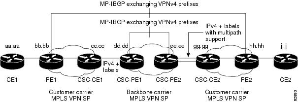
In the following example and in Figure 4, the NSF/SSO—MPLS VPN feature is configured on an existing MPLS VPN.
Enabling SSO on a Cisco 7500 Series Router
The following commands are used to enable SSO on the routers:
•
•
•
The configuration examples are the same for both platforms with the exception that the following configuration boot commands are seen in the beginning of a Cisco 7500 series router configuration (and not in a Cisco 10000 series router configuration):
boot system slot0:rsp-pv-mzhw-module slot 2 image slot0:rsp-pv-mzhw-module slot 3 image slot0:rsp-pv-mzEnabling SSO on a Cisco 10000 Series Router
The SSO mode is enabled by default.
Enabling NSF on Both the Cisco 7500 Series and Cisco 10000 Series Routers
The following commands are used to enable NSF for the routing protocols, such as BGP and OSPF, and for the label distribution protocols, such as BGP and LDP:
•
•
•
•
•
Note
This section and Figure 4 provide an example of a backbone carrier and a customer carrier who are both BGP/MPLS VPN service providers. The example shows how BGP is enabled to distribute routes and MPLS labels between PE and CE routers.
Figure 4 MPLS VPN CSC Configuration 3 with MPLS VPN: NSF and SSO
In Figure 4, the subnet mask is 255.255.255.252.
The routers have the following characteristics:
•
•
•
•
CE1 Configuration
ip cefinterface Loopback0ip address aa.aa.aa.aa 255.255.255.255!interface Ethernet3/3ip address mm.0.0.1 255.0.0.0!router bgp 300no synchronizationbgp log-neighbor-changesbgp graceful-restart restart-time 120bgp graceful-restart stalepath-time 360bgp graceful-restarttimers bgp 10 30redistribute connected !Exchange routesneighbor mm.0.0.2 remote-as 200 !learned from PE1.neighbor mm.0.0.2 advertisement-interval 5no auto-summaryPE1 Configuration
redundancymode ssoip cef distributed!ip vrf vpn2rd 200:1route-target export 200:1route-target import 200:1mpls ldp graceful-restartmpls label protocol ldp!interface Loopback0ip address bb.bb.bb.bb 255.255.255.255!interface Ethernet3/0 =====> interface FastEthernet3/0/0 on a Cisco 10000 series routerip address nn.0.0.1 255.0.0.0no ip mroute-cachempls label protocol ldpmpls ip!interface Ethernet3/3 =====> interface FastEthernet3/0/3 on a Cisco 10000 series routerip vrf forwarding vpn2ip address mm.0.0.2 255.0.0.0no ip mroute-cache!router ospf 200log-adjacency-changesauto-cost reference-bandwidth 1000nsf enforce globalredistribute connected subnetspassive-interface Ethernet3/3 ===> passive-interface FastEthernet3/0/3 on a Cisco 10000network bb.bb.bb.bb 0.0.0.0 area 200network nn.0.0.0 0.255.255.255 area 200!router bgp 200no bgp default ipv4-unicastbgp log-neighbor-changesbgp graceful-restart restart-time 120bgp graceful-restart stalepath-time 360bgp graceful-restarttimers bgp 10 30neighbor hh.hh.hh.hh remote-as 200neighbor hh.hh.hh.hh update-source Loopback0!address-family vpnv4 !VPNv4 session with PE2.neighbor hh.hh.hh.hh activateneighbor hh.hh.hh.hh send-community extendedbgp dampening 30exit-address-family!address-family ipv4 vrf vpn2neighbor mm.0.0.1 remote-as 300neighbor mm.0.0.1 activateneighbor mm.0.0.1 as-overrideneighbor mm.0.0.1 advertisement-interval 5no auto-summaryno synchronizationbgp dampening 30exit-address-familyCSC-CE1 Configuration
ip cef!mpls ldp graceful-restartmpls label protocol ldp!interface Loopback0ip address cc.cc.cc.cc 255.255.255.255!interface Ethernet3/0ip address pp.0.0.1 255.0.0.0mpls forwarding bgp!interface Ethernet4/0ip address nn.0.0.2 255.0.0.0no ip mroute-cachempls label protocol ldpmpls ip!router ospf 200log-adjacency-changesauto-cost reference-bandwidth 1000nsf enforce globalredistribute connected subnets !Exchange routesredistribute bgp 200 metric 3 subnets !learned from PE1.passive-interface ATM1/0passive-interface Ethernet3/0network cc.cc.cc.cc 0.0.0.0 area 200network nn.0.0.0 0.255.255.255 area 200!router bgp 200no bgp default ipv4-unicastbgp log-neighbor-changesbgp graceful-restart restart-time 120bgp graceful-restart stalepath-time 360bgp graceful-restarttimers bgp 10 30neighbor pp.0.0.2 remote-as 100neighbor pp.0.0.2 update-source Ethernet3/0no auto-summary!address-family ipv4redistribute connectedredistribute ospf 200 metric 4 match internalneighbor pp.0.0.2 activateneighbor pp.0.0.2 send-labelno auto-summaryno synchronizationbgp dampening 30exit-address-familyCSC-PE1 Configuration
redundancymode ssoip cef distributed!ip vrf vpn1rd 100:1route-target export 100:1route-target import 100:1mpls ldp graceful-restartmpls label protocol ldp!interface Loopback0ip address dd.dd.dd.dd 255.255.255.255!interface Ethernet3/1 =====> interface FastEthernet3/0/1 on a Cisco 10000 series routerip vrf forwarding vpn1ip address pp.0.0.2 255.0.0.0mpls forwarding bgp!interface ATM0/1/0no ip address!interface ATM0/1/0.1 point-to-pointip unnumbered Loopback0no atm enable-ilmi-trapmpls label protocol ldpmpls ip!router ospf 100log-adjacency-changesauto-cost reference-bandwidth 1000nsf enforce globalredistribute connected subnetspassive-interface Ethernet3/1network dd.dd.dd.dd 0.0.0.0 area 100!router bgp 100no bgp default ipv4-unicastbgp log-neighbor-changesbgp graceful-restart restart-time 120bgp graceful-restart stalepath-time 360bgp graceful-restarttimers bgp 10 30neighbor ee.ee.ee.ee remote-as 100neighbor ee.ee.ee.ee update-source Loopback0!address-family vpnv4 !VPNv4 session with CSC-PE2.neighbor ee.ee.ee.ee activateneighbor ee.ee.ee.ee send-community extendedbgp dampening 30exit-address-family!address-family ipv4 vrf vpn1neighbor pp.0.0.1 remote-as 200neighbor pp.0.0.1 activateneighbor pp.0.0.1 as-overrideneighbor pp.0.0.1 advertisement-interval 5neighbor pp.0.0.1 send-labelno auto-summaryno synchronizationbgp dampening 30exit-address-familyCSC-PE2 Configuration
redundancymode ssoip cef distributed!ip vrf vpn1rd 100:1route-target export 100:1route-target import 100:1mpls ldp graceful-restartmpls label protocol ldp!interface Loopback0ip address ee.ee.ee.ee 255.255.255.255!interface Ethernet5/0 =====> interface FastEthernet5/0/0 on a Cisco 10000 series routerip vrf forwarding vpn1ip address ss.0.0.2 255.0.0.0mpls forwarding bgpno ip route-cache distributedclock source internal!interface ATM2/1/0no ip address!interface ATM2/1/0.1 point-to-pointip unnumbered Loopback0no atm enable-ilmi-trapmpls label protocol ldpmpls ip!router ospf 100log-adjacency-changesauto-cost reference-bandwidth 1000nsf enforce globalredistribute connected subnetspassive-interface Ethernet5/0 ====> passive-interface FastEthernet5/0/0 on a Cisco 10000passive-interface ATM3/0/0network ee.ee.ee.ee 0.0.0.0 area 100!router bgp 100no bgp default ipv4-unicastbgp log-neighbor-changesbgp graceful-restart restart-time 120bgp graceful-restart stalepath-time 360bgp graceful-restarttimers bgp 10 30neighbor dd.dd.dd.dd remote-as 100neighbor dd.dd.dd.dd update-source Loopback0!address-family vpnv4 !VPNv4 session with CSC-PE1.neighbor dd.dd.dd.dd activateneighbor dd.dd.dd.dd send-community extendedbgp dampening 30exit-address-family!address-family ipv4 vrf vpn1neighbor ss.0.0.1 remote-as 200neighbor ss.0.0.1 activateneighbor ss.0.0.1 as-overrideneighbor ss.0.0.1 advertisement-interval 5neighbor ss.0.0.1 send-labelno auto-summaryno synchronizationbgp dampening 30exit-address-familyCSC-CE2 Configuration
ip cef!mpls ldp graceful-restartmpls label protocol ldp!interface Loopback0ip address gg.gg.gg.gg 255.255.255.255!interface Ethernet2/2ip address ss.0.0.2 255.0.0.0no ip mroute-cachempls forwarding bgp!interface ATM3/1/0.1 point-to-pointip address yy.0.0.1 255.0.0.0mpls label protocol ldpmpls ip!router ospf 200log-adjacency-changesauto-cost reference-bandwidth 1000nsf enforce globalredistribute connected subnets !Exchange routesredistribute bgp 200 metric 3 subnets !learned from PE2.passive-interface ATM3/1/0.1network gg.gg.gg.gg 0.0.0.0 area 200network ss.0.0.0 0.255.255.255 area 200!router bgp 200no bgp default ipv4-unicastbgp log-neighbor-changesbgp graceful-restart restart-time 120bgp graceful-restart stalepath-time 360bgp graceful-restarttimers bgp 10 30neighbor yy.0.0.2 remote-as 100neighbor yy.0.0.2 update-source ATM3/1/0.1no auto-summary!address-family ipv4redistribute connectedredistribute ospf 200 metric 4 match internalneighbor yy.0.0.2 activateneighbor yy.0.0.2 send-labelno auto-summaryno synchronizationbgp dampening 30exit-address-familyPE2 Configuration
redundancymode ssoip cef distributed!ip vrf vpn2rd 200:1route-target export 200:1route-target import 200:1!mpls ldp graceful-restartmpls label protocol ldp!interface Loopback0ip address hh.hh.hh.hh 255.255.255.255!interface Ethernet3/6 =====> interface FastEthernet3/0/6 on a Cisco 10000 series routerip vrf forwarding vpn2ip address tt.0.0.2 255.0.0.0!interface ATM5/0.1 point2pointip address qq.0.0.1 255.0.0.0no atm enable-ilmi-trapno ip mroute-cachempls label protocol ldpmpls ip!router bgp 200no bgp default ipv4-unicastbgp log-neighbor-changesbgp graceful-restart restart-time 120bgp graceful-restart stalepath-time 360bgp graceful-restarttimers bgp 10 30neighbor bb.bb.bb.bb remote-as 200neighbor bb.bb.bb.bb update-source Loopback0!address-family vpnv4 !VPNv4 session with PE1.neighbor bb.bb.bb.bb activateneighbor bb.bb.bb.bb send-community extendedbgp dampening 30exit-address-family!address-family ipv4 vrf vpn2neighbor tt.0.0.1 remote-as 300neighbor tt.0.0.1 activateneighbor tt.0.0.1 as-overrideneighbor tt.0.0.1 advertisement-interval 5no auto-summaryno synchronizationbgp dampening 30exit-address-familyCE2 Configuration
ip cef!interface Loopback0ip address jj.jj.jj.jj 255.255.255.255!interface Ethernet3/6ip address tt.0.0.1 255.0.0.0!router bgp 300bgp graceful-restart restart-time 120bgp graceful-restart stalepath-time 360bgp graceful-restartno synchronizationbgp log-neighbor-changestimers bgp 10 30 !Exchange routesredistribute connected !learned from PE2.redistribute ospf 300 match internal external 1 external 2neighbor tt.0.0.2 remote-as 200neighbor tt.0.0.2 advertisement-interval 5no auto-summaryNSF/SSO—MPLS VPN for an Inter-AS Network Using BGP to Distribute Routes and MPLS Labels: Example
In Figure 5 and in the following example, the NSF/SSO—MPLS VPN feature is configured on the existing MPLS VPN Inter-AS configuration.
Enabling SSO on a Cisco 7500 Series Router
The following commands are used to enable SSO on the routers:
•
•
•
The configuration examples are the same for both platforms with the exception that the following configuration boot commands are seen in the beginning of a Cisco 7500 series router configuration (and not in a Cisco 10000 series router configuration):
boot system slot0:rsp-pv-mzhw-module slot 2 image slot0:rsp-pv-mzhw-module slot 3 image slot0:rsp-pv-mzEnabling SSO on a Cisco 10000 Series Router
The SSO mode is enabled by default.
Enabling NSF on Both the Cisco 7500 Series and Cisco 10000 Series Routers
The following commands are used to enable NSF for the routing protocols, such as BGP and OSPF, and for the label distribution protocols, such as BGP and LDP:
•
•
•
•
•
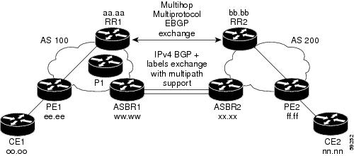
Inter-AS with IPv4 BGP Label Distribution enables you to set up a VPN so that the ASBRs exchange IPv4 routes with MPLS labels of the PE routers. Route reflectors (RRs) exchange VPNv4 routes by using Multihop, Multiprotocol EBGP. This configuration saves the ASBRs from having to store all of the VPNv4 routes. Using the RRs to store the VPNv4 routes and forward them to the PE routers improves scalability.
Figure 5 shows two MPLS VPN service providers. They distribute VPNv4 addresses between the RRs and IPv4 routes and MPLS labels between ASBRs.
Figure 5 MPLS VPN Inter-AS Configuration with MPLS VPN: NSF/SSO
Figure 5 shows the two techniques you can use to distribute the VPNv4 routes and the IPv4 routes and MPLS labels of remote PEs and RRs to local PEs and RRs:
•
•
Note
RR1 Configuration
The configuration example for RR1 specifies the following:
•
•
•
redundancymode ssoip subnet-zeroip cef distributed!interface Loopback0ip address aa.aa.aa.aa 255.255.255.255!interface Serial1/2 =======> Serial1/0/2 on a Cisco 10000 series routerip address dd.0.0.2 255.0.0.0clockrate 124061!router ospf 10log-adjacency-changesauto-cost reference-bandwidth 1000network aa.aa.aa.aa 0.0.0.0 area 100network dd.0.0.0 0.255.255.255 area 100!router bgp 100bgp cluster-id 1bgp log-neighbor-changesbgp graceful-restart restart-time 120bgp graceful-restart stalepath-time 360bgp graceful-restarttimers bgp 10 30neighbor ee.ee.ee.ee remote-as 100neighbor ee.ee.ee.ee update-source Loopback0neighbor ww.ww.ww.ww remote-as 100neighbor ww.ww.ww.ww update-source Loopback0neighbor bb.bb.bb.bb remote-as 200neighbor bb.bb.bb.bb ebgp-multihop 255neighbor bb.bb.bb.bb update-source Loopback0no auto-summary!address-family ipv4neighbor ee.ee.ee.ee activateneighbor ee.ee.ee.ee route-reflector-client !IPv4+labels session to PE1neighbor ee.ee.ee.ee send-labelneighbor ww.ww.ww.ww activateneighbor ww.ww.ww.ww route-reflector-client !IPv4+labels session to ASBR1neighbor ww.ww.ww.ww send-labelno neighbor bb.bb.bb.bb activateno auto-summaryno synchronizationexit-address-family!address-family vpnv4neighbor ee.ee.ee.ee activateneighbor ee.ee.ee.ee route-reflector-client !VPNv4 session with PE1neighbor ee.ee.ee.ee send-community extendedneighbor bb.bb.bb.bb activateneighbor bb.bb.bb.bb next-hop-unchanged!MH-VPNv4 session with RR2 with next hop unchangedneighbor bb.bb.bb.bb send-community extendedexit-address-family!ip default-gateway 10.3.0.1no ip classless!endASBR1 Configuration
ASBR1 exchanges IPv4 routes and MPLS labels with ASBR2.
redundancymode ssoip cef distributedip subnet-zerompls ldp graceful-restartmpls label protocol ldp!interface Loopback0ip address ww.ww.ww.ww 255.255.255.255no ip route-cacheno ip mroute-cache!interface Ethernet0/2 =====> interface FastEthernet1/0/2 on a Cisco 10000 series routerip address hh.0.0.2 255.0.0.0no ip mroute-cachempls forwarding bgp!interface Ethernet0/3 =====> interface FastEthernet1/0/3 on a Cisco 10000 series routerip address dd.0.0.1 255.0.0.0no ip mroute-cachempls label protocol ldpmpls ip!router ospf 10log-adjacency-changesauto-cost reference-bandwidth 1000nsf enforce globalredistribute connected subnetspassive-interface Ethernet0/2 =====> passive-interface FastEthernet1/0/2 on a Cisco 10000network ww.ww.ww.ww 0.0.0.0 area 100network dd.0.0.0 0.255.255.255 area 100!router bgp 100bgp log-neighbor-changesbgp graceful-restart restart-time 120bgp graceful-restart stalepath-time 360bgp graceful-restarttimers bgp 10 30neighbor aa.aa.aa.aa remote-as 100neighbor aa.aa.aa.aa update-source Loopback0neighbor hh.0.0.1 remote-as 200no auto-summary! Redistributing IGP into BGP! so that PE1 & RR1 loopbacks! get into the BGP table.address-family ipv4redistribute ospf 10neighbor aa.aa.aa.aa activateneighbor aa.aa.aa.aa send-labelneighbor hh.0.0.1 activateneighbor hh.0.0.1 advertisement-interval 5neighbor hh.0.0.1 send-labelno auto-summaryno synchronizationexit-address-family!ip default-gateway 10.3.0.1ip classlessendRR2 Configuration
RR2 exchanges VPNv4 routes with RR1 through Multihop, Multiprotocol EBGP. In this configuration, the next hop information and the VPN label are preserved across the autonomous systems.
ip subnet-zeroip cef!interface Loopback0ip address bb.bb.bb.bb 255.255.255.255!interface Serial1/1ip address ii.0.0.2 255.0.0.0no ip mroute-cache!router ospf 20log-adjacency-changesnetwork bb.bb.bb.bb 0.0.0.0 area 200network ii.0.0.0 0.255.255.255 area 200!router bgp 200bgp cluster-id 1bgp log-neighbor-changesbgp graceful-restart restart-time 120bgp graceful-restart stalepath-time 360bgp graceful-restarttimers bgp 10 30neighbor aa.aa.aa.aa remote-as 100neighbor aa.aa.aa.aa ebgp-multihop 255neighbor aa.aa.aa.aa update-source Loopback0neighbor ff.ff.ff.ff remote-as 200neighbor ff.ff.ff.ff update-source Loopback0no auto-summary!address-family vpnv4neighbor aa.aa.aa.aa activateneighbor aa.aa.aa.aa next-hop-unchanged!Multihop VPNv4 session with RR1 with next-hop unchangedneighbor aa.aa.aa.aa send-community extendedneighbor ff.ff.ff.ff activateneighbor ff.ff.ff.ff route-reflector-client !VPNv4 session with PE2neighbor ff.ff.ff.ff send-community extendedexit-address-family!ip default-gateway 10.3.0.1no ip classlessendASBR2 Configuration
ASBR2 exchanges IPv4 routes and MPLS labels with ASBR1. However, in contrast to ASBR1, ASBR2 does not use the RR to reflect IPv4 routes and MPLS labels to PE2. ASBR2 redistributes the IPv4 routes and MPLS labels learned from ASBR1 into IGP. PE2 can reach these prefixes.
ip subnet-zeroip cef!mpls ldp graceful-restartmpls label protocol ldp!interface Loopback0ip address xx.xx.xx.xx 255.255.255.255!interface Ethernet1/0ip address hh.0.0.1 255.0.0.0no ip mroute-cachempls forwarding bgp!interface Ethernet1/2ip address jj.0.0.1 255.0.0.0no ip mroute-cachempls label protocol ldpmpls ip!router ospf 20log-adjacency-changesauto-cost reference-bandwidth 1000nsf enforce globalredistribute connected subnetsredistribute bgp 200 subnetspassive-interface Ethernet1/0! redistributing the routes learned from ASBR1!(EBGP+labels session) into IGP so that PE2! will learn themnetwork xx.xx.xx.xx 0.0.0.0 area 200network jj..0.0 0.255.255.255 area 200!router bgp 200bgp log-neighbor-changesbgp graceful-restart restart-time 120bgp graceful-restart stalepath-time 360bgp graceful-restarttimers bgp 10 30neighbor bb.bb.bb.bb remote-as 200neighbor bb.bb.bb.bb update-source Loopback0neighbor hh.0.0.2 remote-as 100no auto-summary!address-family ipv4redistribute ospf 20! Redistributing IGP into BGP! so that PE2 & RR2 loopbacks! will get into the BGP-4 tableneighbor hh.0.0.2 activateneighbor hh.0.0.2 advertisement-interval 5neighbor hh.0.0.2 send-labelno auto-summaryno synchronizationexit-address-family!address-family vpnv4neighbor bb.bb.bb.bb activateneighbor bb.bb.bb.bb send-community extendedexit-address-family!ip default-gateway 10.3.0.1ip classless!endNSF/SSO—MPLS VPN for an Inter-AS Network That Uses BGP to Distribute Routes and MPLS Labels over a Non-MPLS VPN Service Provider: Example
In this example, the NSF/SSO—MPLS VPN feature is configured on an existing MPLS VPN.
Enabling SSO on a Cisco 7500 Series Router
The following commands are used to enable SSO on the routers:
•
•
•
The configuration examples are the same for both platforms with the exception that the following configuration boot commands are seen in the beginning of a Cisco 7500 series router configuration (and not in a Cisco 10000 series router configuration):
boot system slot0:rsp-pv-mzhw-module slot 2 image slot0:rsp-pv-mzhw-module slot 3 image slot0:rsp-pv-mzEnabling SSO on a Cisco 10000 Series Router
The SSO mode is enabled by default.
Enabling NSF on Both the Cisco 7500 Series and Cisco 10000 Series Routers
The following commands are used to enable NSF for the routing protocols, such as BGP and OSPF, and for the label distribution protocols, such as BGP and LDP:
•
•
•
•
•
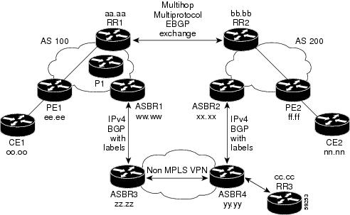
Figure 6 shows two MPLS VPN service providers that are connected through a non-MPLS VPN service provider. The autonomous system in the middle of the network is configured as a backbone autonomous system that uses LDP to distribute MPLS labels. You can also use traffic engineering tunnels instead of LDP to build the LSP across the non-MPLS VPN service provider.
Figure 6 MPLS VPN Inter-AS Configuration 2 with MPLS VPN: NSF/SSO
Note
RR1 Configuration
The configuration example for RR1 specifies the following:
•
•
•
ip subnet-zeroip cef!interface Loopback0ip address aa.aa.aa.aa 255.255.255.255!interface Serial1/2ip address dd.0.0.2 255.0.0.0clockrate 124061!router ospf 10log-adjacency-changesauto-cost reference-bandwidth 1000network aa.aa.aa.aa 0.0.0.0 area 100network dd.dd.0.0.0 0.255.255.255 area 100!router bgp 100bgp cluster-id 1bgp log-neighbor-changesbgp graceful-restart restart-time 120bgp graceful-restart stalepath-time 360bgp graceful-restarttimers bgp 10 30neighbor ee.ee.ee.ee remote-as 100neighbor ee.ee.ee.ee update-source Loopback0neighbor ww.ww.ww.ww remote-as 100neighbor ww.ww.ww.ww update-source Loopback0neighbor bb.bb.bb.bb remote-as 200neighbor bb.bb.bb.bb ebgp-multihop 255neighbor bb.bb.bb.bb update-source Loopback0no auto-summary!address-family ipv4neighbor ee.ee.ee.ee activateneighbor ee.ee.ee.ee route-reflector-client !IPv4+labels session to PE1neighbor ee.ee.ee.ee send-labelneighbor ww.ww.ww.ww activateneighbor ww.ww.ww.ww route-reflector-client !IPv4+labels session to ASBR1neighbor ww.ww.ww.ww send-labelno neighbor bb.bb.bb.bb activateno auto-summaryno synchronizationexit-address-family!address-family vpnv4neighbor ee.ee.ee.ee activateneighbor ee.ee.ee.ee route-reflector-client !VPNv4 session with PE1neighbor ee.ee.ee.ee send-community extendedneighbor bb.bb.bb.bb activateneighbor bb.bb.bb.bb next-hop-unchanged!MH-VPNv4 session with RR2 with next-hop-unchangedneighbor bb.bb.bb.bb send-community extendedexit-address-family!ip default-gateway 10.3.0.1no ip classless!snmp-server engineID local 00000009020000D0584B25C0snmp-server community public ROsnmp-server community write RWno snmp-server ifindex persistsnmp-server packetsize 2048!endASBR1 Configuration
ASBR1 exchanges IPv4 routes and MPLS labels with ASBR2.
redundancymode ssoip subnet-zeroip cef distributedmpls ldp graceful-restartmpls label protocol ldp!interface Loopback0ip address ww.ww.ww.ww 255.255.255.255no ip route-cacheno ip mroute-cache!interface Serial3/0/0ip address kk.0.0.2 255.0.0.0mpls forwarding bgpip route-cache distributed!interface Ethernet0/3ip address dd.0.0.1 255.0.0.0no ip mroute-cachempls label protocol ldpmpls ip!router ospf 10log-adjacency-changesnsf enforce globalauto-cost reference-bandwidth 1000redistribute connected subnetspassive-interface Serial3/0/0network ww.ww.ww.ww 0.0.0.0 area 100network dd.0.0.0 0.255.255.255 area 100!router bgp 100bgp log-neighbor-changesbgp graceful-restart restart-time 120bgp graceful-restart stalepath-time 360bgp graceful-restarttimers bgp 10 30neighbor aa.aa.aa.aa remote-as 100neighbor aa.aa.aa.aa update-source Loopback0neighbor kk.0.0.1 remote-as 200no auto-summary!address-family ipv4redistribute ospf 10 ! Redistributing IGP into BGPneighbor aa.aa.aa.aa activate ! so that PE1 & RR1 loopbacksneighbor aa.aa.aa.aa send-label ! get into BGP tableneighbor kk.0.0.1 activateneighbor kk.0.0.1 advertisement-interval 5neighbor kk.0.0.1 send-labelno auto-summaryno synchronizationexit-address-family!ip default-gateway 10.3.0.1ip classless!endRR2 Configuration
RR2 exchanges VPNv4 routes with RR1, using Multihop, Multiprotocol EBGP. This configuration also preserves the next hop information and the VPN label across the autonomous systems.
ip subnet-zeroip cef!interface Loopback0ip address bb.bb.bb.bb 255.255.255.255!interface Serial1/1ip address ii.0.0.2 255.0.0.0no ip mroute-cache!router ospf 20log-adjacency-changesnetwork bb.bb.bb.bb 0.0.0.0 area 200network ii.0.0.0 0.255.255.255 area 200!router bgp 200bgp cluster-id 1bgp log-neighbor-changesbgp graceful-restart restart-time 120bgp graceful-restart stalepath-time 360bgp graceful-restarttimers bgp 10 30neighbor aa.aa.aa.aa remote-as 100neighbor aa.aa.aa.aa ebgp-multihop 255neighbor aa.aa.aa.aa update-source Loopback0neighbor ff.ff.ff.ff remote-as 200neighbor ff.ff.ff.ff update-source Loopback0no auto-summary!address-family vpnv4neighbor aa.aa.aa.aa activateneighbor aa.aa.aa.aa next-hop-unchanged!MH Vpnv4 session with RR1 with next-hop-unchangedneighbor aa.aa.aa.aa send-community extendedneighbor ff.ff.ff.ff activateneighbor ff.ff.ff.ff route-reflector-client !Vpnv4 session with PE2neighbor ff.ff.ff.ff send-community extendedexit-address-family!ip default-gateway 10.3.0.1no ip classless!endASBR2 Configuration
ASBR2 exchanges IPv4 routes and MPLS labels with ASBR1. However, in contrast to ASBR1, ASBR2 does not use the RR to reflect IPv4 routes and MPLS labels to PE2. Instead, ASBR2 redistributes the IPv4 routes and MPLS labels learned from ASBR1 into IGP. PE2 can now reach these prefixes.
redundancymode ssoip subnet-zeroip cef distributed!mpls ldp graceful-restartmpls label protocol ldp!interface Loopback0ip address xx.xx.xx.xx 255.255.255.255!interface Ethernet0/1 =====> interface FastEthernet1/0/1 on a Cisco 10000 series routerip address qq.0.0.2 255.0.0.0mpls forwarding bgp!interface Ethernet1/2 =====> interface FastEthernet1/1/2 on a Cisco 10000 series routerip address jj.0.0.1 255.0.0.0no ip mroute-cachempls label protocol ldpmpls ip!router ospf 20log-adjacency-changesauto-cost reference-bandwidth 1000nsf enforce globalredistribute connected subnetsredistribute bgp 200 subnets!redistributing the routes learned from ASBR4!(EBGP+labels session) into IGP so that PE2!will learn thempassive-interface Ethernet0/1 ====> passive-interface FastEthernet1/0/1 on a Cisco 10000network xx.xx.xx.xx 0.0.0.0 area 200network jj.0.0.0 0.255.255.255 area 200!router bgp 200bgp log-neighbor-changesbgp graceful-restart restart-time 120bgp graceful-restart stalepath-time 360bgp graceful-restarttimers bgp 10 30neighbor bb.bb.bb.bb remote-as 200neighbor bb.bb.bb.bb update-source Loopback0neighbor qq.0.0.1 remote-as 100no auto-summary!address-family ipv4! Redistributing IGP into BGP redistribute ospf 20! so that PE2 & RR2 loopbacks! will get into the BGP-4 tableneighbor qq.0.0.1 activateneighbor qq.0.0.1 advertisement-interval 5neighbor qq.0.0.1 send-labelno auto-summaryno synchronizationexit-address-family!address-family vpnv4neighbor bb.bb.bb.bb activateneighbor bb.bb.bb.bb send-community extendedexit-address-family!ip default-gateway 10.3.0.1ip classless!endASBR3 Configuration
ASBR3 belongs to a non-MPLS VPN service provider. ASBR3 exchanges IPv4 routes and MPLS labels with ASBR1. ASBR3 also passes the routes learned from ASBR1 to ASBR3 through RR3.
Note
ip subnet-zeroip cef!interface Loopback0ip address yy.yy.yy.yy 255.255.255.255no ip route-cacheno ip mroute-cache!interface Hssi4/0 ========> only on a Cisco 7500 series routerip address mm.0.0.0.1 255.0.0.0 ========> only on a Cisco 7500 series routerno ip mroute-cache ========> only on a Cisco 7500 series routermpls ip ========> only on a Cisco 7500 series routerhssi internal-clock ========> only on a Cisco 7500 series router!interface Serial5/0 ========> Serial5/0/0 on a Cisco 10000 series routerip address kk.0.0.1 255.0.0.0no ip mroute-cacheload-interval 30clockrate 124061mpls forwarding bgp!router ospf 30log-adjacency-changesauto-cost reference-bandwidth 1000redistribute connected subnetsnetwork yy.yy.yy.yy 0.0.0.0 area 300network mm.0.0.0 0.255.255.255 area 300 ========> only on a Cisco 7500 series router!router bgp 300bgp log-neighbor-changesbgp graceful-restart restart-time 120bgp graceful-restart stalepath-time 360bgp graceful-restarttimers bgp 10 30neighbor cc.cc.cc.cc remote-as 300neighbor cc.cc.cc.cc update-source Loopback0neighbor kk.0.0.2 remote-as 100no auto-summary!address-family ipv4neighbor cc.cc.cc.cc activate ! IBGP+labels session with RR3neighbor cc.cc.cc.cc send-labelneighbor kk.0.0.2 activate ! EBGP+labels session with ASBR1neighbor kk.0.0.2 advertisement-interval 5neighbor kk.0.0.2 send-labelno auto-summaryno synchronizationexit-address-family!endRR3 Configuration
RR3 is a non-MPLS VPN RR that reflects IPv4 routes with MPLS labels to ASBR3 and ASBR4.
ip subnet-zero!interface Loopback0ip address cc.cc.cc.cc 255.255.255.255!interface POS0/2 =========> interface POS1/0/2 on a Cisco 10000 series routerip address pp.0.0.1 255.0.0.0no ip route-cache cefno ip route-cacheno ip mroute-cachecrc 16clock source internal!router ospf 30log-adjacency-changesnetwork cc.cc.cc.cc 0.0.0.0 area 300network pp.0.0.0 0.255.255.255 area 300!router bgp 300bgp log-neighbor-changesbgp graceful-restart restart-time 120bgp graceful-restart stalepath-time 360bgp graceful-restartneighbor zz.zz.zz.zz remote-as 300neighbor zz.zz.zz.zz update-source Loopback0neighbor yy.yy.yy.yy remote-as 300neighbor yy.yy.yy.yy update-source Loopback0no auto-summary!address-family ipv4neighbor zz.zz.zz.zz activateneighbor zz.zz.zz.zz route-reflector-clientneighbor zz.zz.zz.zz send-label ! IBGP+labels session with ASBR3neighbor yy.yy.yy.yy activateneighbor yy.yy.yy.yy route-reflector-clientneighbor yy.yy.yy.yy send-label ! IBGP+labels session with ASBR4no auto-summaryno synchronizationexit-address-family!ip default-gateway 10.3.0.1ip classless!endASBR4 Configuration
ASBR4 belongs to a non-MPLS VPN service provider. ASBR4 and ASBR3 exchange IPv4 routes and MPLS labels by means of RR3.
Note
redundancymode ssompls ldp graceful-restartip subnet-zeroip cef distributed!interface Loopback0ip address zz.zz.zz.zz 255.255.255.255no ip route-cacheno ip mroute-cache!interface Ethernet0/2 =====> interface FastEthernet1/0/2 on a Cisco 10000 series routerip address qq.0.0.1 255.0.0.0no ip mroute-cachempls forwarding bgp!interface POS1/1/0ip address pp.0.0.2 255.0.0.0ip route-cache distributed!interface Hssi2/1/1 ========> only on a Cisco 7500 series routerip address mm.0.0.2 255.0.0.0 ========> only on a Cisco 7500 series routerip route-cache distributed ========> only on a Cisco 7500 series routerno ip mroute-cache ========> only on a Cisco 7500 series routermpls label protocol ldp ========> only on a Cisco 7500 series routermpls ip ========> only on a Cisco 7500 series routerhssi internal-clock ========> only on a Cisco 7500 series router!router ospf 30log-adjacency-changesnsf enforce globalauto-cost reference-bandwidth 1000redistribute connected subnetspassive-interface Ethernet0/2 ====> passive-interface FastEthernet1/0/2 on a Cisco 10000network zz.zz.zz.zz 0.0.0.0 area 300network pp.0.0.0 0.255.255.255 area 300network mm.0.0.0 0.255.255.255 area 300!router bgp 300bgp log-neighbor-changesbgp graceful-restart restart-time 120bgp graceful-restart stalepath-time 360bgp graceful-restarttimers bgp 10 30neighbor cc.cc.cc.cc remote-as 300neighbor cc.cc.cc.cc update-source Loopback0neighbor qq.0.0.2 remote-as 200no auto-summary!address-family ipv4neighbor cc.cc.cc.cc activateneighbor cc.cc.cc.cc send-labelneighbor qq.0.0.2 activateneighbor qq.0.0.2 advertisement-interval 5neighbor qq.0.0.2 send-labelno auto-summaryno synchronizationexit-address-family!ip classlessendAdditional References
The following sections provide additional information related to the NSF/SSO—MPLS VPN feature.
Related Documents
Nonstop forwarding and BGP Graceful Restart
Stateful awitchover
Basic VPNs, MPLS VPN interautonomous systems, MPLS VPN Carrier Supporting Carrier
"Part 4: MPLS Virtual Private Networks" module in the Cisco IOS Multiprotocol Label Switching Configuration Guide, Release 12.4
Standards
draft-ietf-mpls-bgp-mpls-restart.txt
Graceful Restart Mechanism for BGP with MPLS
draft-ietf-mpls-idr-restart.txt
Graceful Restart Mechanism for BGP
MIBs
MPLS VPN MIB
To locate and download MIBs for selected platforms, Cisco IOS releases, and feature sets, use Cisco MIB Locator found at the following URL:
RFCs
RFC 1163
A Border Gateway Protocol
RFC 1164
Application of the Border Gateway Protocol in the Internet
RFC 2283
Multiprotocol Extensions for BGP-4
RFC 2547
BGP/MPLS VPNs
Technical Assistance
Command Reference
This section documents only new and modified commands.
mpls forwarding bgp
To enable Multiprotocol Label Switching (MPLS) nonstop forwarding on an interface that uses Border Gateway Protocol (BGP) as the label distribution protocol, use the mpls forwarding bgp command in interface configuration mode. To disable MPLS nonstop forwarding on the interface, use the no form of this command.
mpls forwarding bgp
no mpls forwarding bgp
Syntax Description
This command has no arguments or keywords.
Defaults
MPLS nonstop forwarding is not enabled on the interface.
Command Modes
Interface configuration
Command History
Usage Guidelines
Configure this command on the interfaces of the BGP peers that send and receive labels. If this command is not configured on an interface and a stateful switchover occurs, packets received from an interface are dropped until the BGP session is established in the new route processor.
Issue this command to enable nonstop forwarding on interfaces that use BGP to distribute labels for the following types of VPNs:
•
•
Examples
In the following examples, an interface is configured to save BGP labels in the event of a stateful switchover:
Cisco 7000 Series Example
Router(config)# interface Pos1/0Router(config-if)# mpls forwarding bgpCisco 10000 Series Example
Router(config)# interface Pos1/0/0Router(config-if)# mpls forwarding bgpRelated Commands
show ip bgp labels
To display information about Multiprotocol Label Switching (MPLS) labels from the external Border Gateway Protocol (eBGP) route table, use the show ip bgp labels command in privileged EXEC mode.
show ip bgp labels
Syntax Description
This command has no arguments or keywords.
Command Modes
Privileged EXEC
Command History
Usage Guidelines
Use this command to display eBGP labels associated with an Autonomous System Boundary Router (ASBR).
This command displays labels for BGP routes in the default table only. To display labels in the Virtual Private Network (VPN) routing and forwarding (VRF) tables, use the show ip bgp vpnv4 {all | vrf vrf-name} command with the optional labels keyword.
Examples
The following example shows output for an ASBR using BGP as a label distribution protocol:
Router# show ip bgp labelsNetwork Next Hop In Label/Out Label10.3.0.0/16 0.0.0.0 imp-null/exp-null10.15.15.15/32 10.15.15.15 18/exp-null10.16.16.16/32 0.0.0.0 imp-null/exp-null10.17.17.17/32 10.0.0.1 20/exp-null10.18.18.18/32 10.0.0.1 24/3110.18.18.18/32 10.0.0.1 24/33Table 1 describes the significant fields shown in the display.
Related Commands
show ip bgp vpnv4
To display Virtual Private Network Version 4 (VPNv4) address information from the Border Gateway Protocol (BGP) table, use the show ip bgp vpnv4 command in user EXEC or privileged EXEC mode.
show ip bgp vpnv4 {all | rd route-distinguisher | vrf vrf-name} [rib-failure] [ip-prefix/length [longer-prefixes]] [network-address [mask] [longer-prefixes]] [cidr-only] [community] [community-list] [dampened-paths] [filter-list] [flap-statistics] [inconsistent-as] [neighbors] [paths [line]] [peer-group] [quote-regexp] [regexp] [summary] [labels]
Syntax Description
Command Modes
User EXEC
Privileged EXECCommand History
Usage Guidelines
Use this command to display VPNv4 information from the BGP database. The show ip bgp vpnv4 all command displays all available VPNv4 information. The show ip bgp vpnv4 summary command displays BGP neighbor status. The show ip bgp vpnv4 all labels command displays explicit-null label information.
Examples
The following example shows output for all available VPNv4 information in a BGP routing table:
Router# show ip bgp vpnv4 allBGP table version is 18, local router ID is 10.14.14.14Status codes: s suppressed, d damped, h history, * valid, > best, i - internalOrigin codes: i - IGP, e - EGP,? - incompleteNetwork Next Hop Metric LocPrf Weight PathRoute Distinguisher: 1:101 (default for vrf vpn1)*>i10.6.6.6/32 10.0.0.21 11 100 0 ?*> 10.7.7.7/32 10.150.0.2 11 32768 ?*>i10.69.0.0/30 10.0.0.21 0 100 0 ?*> 10.150.0.0/24 0.0.0.0 0 32768 ?Table 2 describes the significant fields shown in the display.
The following example shows how to display a table of labels for NLRI prefixes that have a route distinguisher value of 100:1.
Router# show ip bgp vpnv4 rd 100:1 labelsNetwork Next Hop In label/Out labelRoute Distinguisher: 100:1 (vrf1)10.0.0.0 10.20.0.60 34/nolabel10.0.0.0 10.20.0.60 35/nolabel10.0.0.0 10.20.0.60 26/nolabel10.20.0.60 26/nolabel10.0.0.0 10.15.0.15 nolabel/26Table 3 describes the significant fields shown in the display.
The following example shows VPNv4 routing entries for the VRF named vpn1:
Router# show ip bgp vpnv4 vrf vpn1BGP table version is 18, local router ID is 10.14.14.14Status codes: s suppressed, d damped, h history, * valid, > best, i - internalOrigin codes: i - IGP, e - EGP,? - incompleteNetwork Next Hop Metric LocPrf Weight PathRoute Distinguisher: 1:101 (default for vrf vpn1)*>i10.6.6.6/32 10.0.0.21 11 100 0 ?*> 10.7.7.7/32 10.150.0.2 11 32768 ?*>i10.69.0.0/30 10.0.0.21 0 100 0 ?*> 10.150.0.0/24 0.0.0.0 0 32768 ?*> 10.0.0.1/32 10.150.0.2 11 32768 ?*>i10.0.0.3/32 10.0.0.21 11 100 0 ?Table 4 describes the significant fields shown in the display.
The following example shows attributes for network 10.22.22.0 that include multipaths and a best path:
Router# show ip bgp vpnv4 all 10.22.22.0BGP routing table entry for 10:1:10.22.22.0/24, version 50Paths:(6 available, best #1)Multipath:iBGPAdvertised to non peer-group peers:10.1.12.122210.22.7.8 (metric 11) from 10.11.3.4 (10.0.0.8)Origin IGP, metric 0, localpref 100, valid, internal, multipath, bestExtended Community:RT:100:1Originator:10.0.0.8, Cluster list:10.1.1.442210.22.1.9 (metric 11) from 10.11.1.2 (10.0.0.9)Origin IGP, metric 0, localpref 100, valid, internal, multipathExtended Community:RT:100:1Originator:10.0.0.9, Cluster list:10.1.1.22Table 5 describes the significant fields shown in the display.
The following example shows routes that BGP could not install in the VRF table:
Router# show ip bgp vpnv4 vrf xyz rib-failureNetwork Next Hop RIB-failure RIB-NH MatchesRoute Distinguisher: 2:2 (default for vrf bar)10.1.1.2/32 10.100.100.100 Higher admin distance No10.111.111.112/32 10.9.9.9 Higher admin distance YesTable 6 describes the significant fields shown in the display.
The following example shows the information displayed on the active and standby Route Processors when they are configured for NSF/SSO: MPLS VPN.
Note
Active Route Processor
Router# show ip bgp vpnv4 all labelsNetwork Next Hop In label/Out labelRoute Distinguisher: 100:1 (vpn1)10.12.12.12/32 0.0.0.0 16/aggregate(vpn1)10.0.0.0/8 0.0.0.0 17/aggregate(vpn1)Route Distinguisher: 609:1 (vpn0)10.13.13.13/32 0.0.0.0 18/aggregate(vpn0)Router# show ip bgp vpnv4 vrf vpn1 labelsNetwork Next Hop In label/Out labelRoute Distinguisher: 100:1 (vpn1)10.12.12.12/32 0.0.0.0 16/aggregate(vpn1)10.0.0.0/8 0.0.0.0 17/aggregate(vpn1)Standby Route Processor
Router# show ip bgp vpnv4 all labelsNetwork Masklen In labelRoute Distinguisher: 100:110.12.12.12 /32 1610.0.0.0 /8 17Route Distinguisher: 609:110.13.13.13 /32 18Router# show ip bgp vpnv4 vrf vpn1 labelsNetwork Masklen In labelRoute Distinguisher: 100:110.12.12.12 /32 1610.0.0.0 /8 17Table 7 describes the significant fields shown in the display.
The following example displays output, including the explicit-null label, from the show ip bgp vpnv4 all labels command on a CSC-PE router:
Router# show ip bgp vpnv4 all labelsNetwork Next Hop In label/Out labelRoute Distinguisher: 100:1 (v1)10.0.0.0/24 10.0.0.0 19/aggregate(v1)10.0.0.1/32 10.0.0.0 20/nolabel10.1.1.1/32 10.0.0.0 21/aggregate(v1)10.10.10.10/32 10.0.0.1 25/exp-null10.168.100.100/3210.0.0.1 23/exp-null10.168.101.101/3210.0.0.1 22/exp-nullTable 8 describes the significant fields shown in the display.
The following example displays separate router IDs for each VRF in the output from an image in Cisco IOS Release 12.2(33)SRA, 12.2(31)SB2, and later releases with the Per-VRF Assignment of BGP Router ID feature configured. The router ID is shown next to the VRF name.
Router# show ip bgp vpnv4 allBGP table version is 5, local router ID is 172.17.1.99Status codes: s suppressed, d damped, h history, * valid, > best, i - internal,r RIB-failure, S StaleOrigin codes: i - IGP, e - EGP, ? - incompleteNetwork Next Hop Metric LocPrf Weight PathRoute Distinguisher: 1:1 (default for vrf vrf_trans) VRF Router ID 10.99.1.2*> 192.168.4.0 0.0.0.0 0 32768 ?Route Distinguisher: 42:1 (default for vrf vrf_user) VRF Router ID 10.99.1.1*> 192.168.5.0 0.0.0.0 0 32768 ?Table 9 describes the significant fields shown in the display.
Related Commands
Feature Information for NSF/SSO—MPLS VPN
Table 10 lists the release history for this feature.
Not all commands may be available in your Cisco IOS software release. For release information about a specific command, see the command reference documentation.
Cisco IOS software images are specific to a Cisco IOS software release, a feature set, and a platform. Use Cisco Feature Navigator to find information about platform support and Cisco IOS software image support. Access Cisco Feature Navigator at http://www.cisco.com/go/fn. You must have an account on Cisco.com. If you do not have an account or have forgotten your username or password, click Cancel at the login dialog box and follow the instructions that appear.
Note
Any Internet Protocol (IP) addresses used in this document are not intended to be actual addresses. Any examples, command display output, and figures included in the document are shown for illustrative purposes only. Any use of actual IP addresses in illustrative content is unintentional and coincidental.
© 2003-2007 Cisco Systems, Inc. All rights reserved.