Downloads |
 Feedback Feedback
|
Table Of Contents
MPLS Label Switching Router MIB
Information from Scalar Objects
Interface Configuration Table and Interface MIB Links
CLI Commands and the MPLS-LSR-MIB
Supported Standards, MIBs, and RFCs
Verifying That the SNMP Agent Has Been Enabled
MPLS Label Switching Router MIB
Feature History
The MPLS Label Switching Router MIB (MPLS-LSR-MIB) allows you to use the Simple Network Management Protocol (SNMP) to remotely monitor a label switching router (LSR) that is using the Multiprotocol Label Switching (MPLS) technology. The MPLS-LSR-MIB mirrors a portion of the Cisco MPLS subsystem; specifically, it mirrors the Label Forwarding Information Base (LFIB).
This document includes the following major sections:
•
Supported Standards, MIBs, and RFCs
Feature Overview
The MPLS-LSR-MIB contains managed objects that support the retrieval of label switching information from a router. The MIB is based on Revision 05 of the IETF MPLS-LSR-MIB. This implementation enables a network administrator to get information on the status, character, and performance of the following:
•
•
•
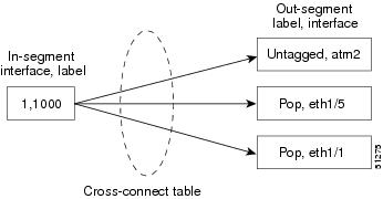
In addition, the network administrator can retrieve the status of cross-connect table entries that associate MPLS segments with each other.
Figure 1 shows the association of the cross-connect table with incoming and outgoing segments (labels).
Figure 1 Label Forwarding with the Cross-Connect Table
Note
The notation used in the MPLS-LSR-MIB follows the conventions defined in Abstract System Notation One (ASN.1). ASN.1 defines an Open System Interconnection (OSI) language used to describe data types independently from particular computer structures and presentation techniques. Each object in the MIB incorporates a DESCRIPTION field that includes an explanation of the object's meaning and usage, which, together with the other characteristics of the object (SYNTAX, MAX-ACCESS, and INDEX) provides sufficient information for management application development, as well as for documentation and testing.
The MPLS-LSR-MIB represents an ASN.1 notation reflecting an idealized MPLS LSR.
A network administrator can access the entries (objects) in the MPLS-LSR-MIB by means of any SNMP-based network management system (NMS). The network administrator can retrieve information in the MPLS-LSR-MIB using standard SNMP get and getnext operations.
Typically, SNMP runs as a low-priority process. The response time for the MPLS-LSR-MIB is expected to be similar to that for other MIBs. The size and structure of the MIB and other MIBs in the system influence response time when you retrieve information from the management database. Traffic through the LSR also affects SNMP performance. The busier the switch is with forwarding activities, the greater the possibility of lower SNMP performance.
MPLS-LSR-MIB Elements
The top-level components of the MPLS-LSR-MIB consist of
•
•
•
This Cisco implementation does not support the notifications defined in the MIB, nor does it support the labelStackTable or the trafficParamTable.
MPLS-LSR-MIB Tables
The Cisco implementation of the MPLS-LSR-MIB supports four main tables: interface configuration, in-segment, out-segment, and cross-connect. The MIB contains three supplementary tables to supply performance information. This implementation does not support the label stack and traffic parameter tables.
Table 1 lists the MPLS-LSR-MIB tables (main and supplementary), their functions, table objects that are supported, and table objects that are not supported.
Information from Scalar Objects
The MPLS-LSR-MIB supports several scalar objects. In the Cisco implementation of the MIB, the following scalar objects are hard-coded to the value indicated and are read-only objects:
•
•
•
•
•
The following scalar objects do not contain information for the MPLS-LSR-MIB and are coded as false:
•
•
•
No trap information exists to support the MIB. Therefore, the following traps are not supported:
•
•
•
•
•
•
Linking Table Elements
In the cross-connect table, cross-connect entries associate incoming segments and interfaces with outgoing segments and interfaces. The following objects index the cross-connect entry:
•
•
•
•
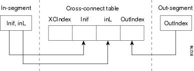
Figure 2 shows the links between the in-segment and the out-segment in the cross-connect table.
Figure 2 Cross-Connect Table Links
Table 2 shows the cross-connect table links you might see in the output from SNMP get operations on the MPLS-LSR-MIB objects that index a cross-connect entry. These objects include
•
•
•
.
Table 2 MPLS LSR Output Showing Cross-Connect Table Links
11 , 1000
5002 = Untagged (topLabel), ATM2
501, 1, 1000, 501
501 = Pop (topLabel), Eth 1/5
502, 1, 1000, 502
502 = Pop (topLabel), Eth, 1/1)
2, 1000
500, 2, 1000, 500
500 = Untagged (topLabel), ATM2
501, 2, 1000, 501
501 = Pop (topLabel), Eth 1/5
502, 2, 1000, 502
502 = Pop (topLabel), Eth, 1/1)
1 All MPLS-enabled interfaces can receive incoming labels.
2 For this implementation of the MPLS-LSR-MIB, the cross-connect index and the out-segment index are the same.
Note
Interface Configuration Table and Interface MIB Links
The MPLS interface configuration table lists interfaces that support MPLS technology. An LSR creates an entry dynamically in this table for each MPLS-capable interface. An interface becomes MPLS-capable when MPLS is enabled on that interface. A non-zero index for an entry in this table points to the ifIndex for the corresponding interface entry in the MPLS-layer in the ifTable of the Interfaces Group MIB.
The ifTable contains information on each interface in the network. Its definition of an interface includes any sublayers of the internetwork layer of the interface. MPLS interfaces fit into this definition of an interface. Therefore, each MPLS-enabled interface is represented by an entry in the ifTable.
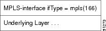
The interrelation of entries in the ifTable is defined by the interfaces stack group of the Interfaces Group MIB. Figure 3 shows how the stack table might appear for MPLS interfaces. The underlying layer refers to any interface that is defined for MPLS internetworking, for example, ATM, Frame Relay, or Ethernet.
Figure 3 Interface Group MIB Stack Table for MPLS Interfaces
Note
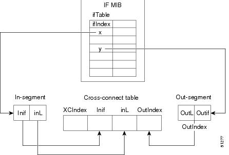
The incoming and outgoing packets include a reference to the interface index for the ifTable of the Interfaces Group MIB. Figure 4 shows the links between MPLS-LSR-MIB objects and the Interfaces Group MIB.
Figure 4 MPLS-LSR-MIB and Interfaces Group MIB Links
•
–
–
•
–
–
•
–
–
•
–
–
–
–
Using the MPLS-LSR-MIB
The MPLS-LSR-MIB enables you to display the contents of the MPLS Label Forwarding Information Base (LFIB). It gives you the same information that you can obtain using the CLI command show mpls forwarding-table.
However, the MPLS-LSR-MIB approach offers these advantages over the CLI command approach:
•
•
•
The following paragraphs describe the MPLS-LSR-MIB structure and show, through the use of an example, how the two approaches to the information display compare.
MPLS-LSR-MIB Structure
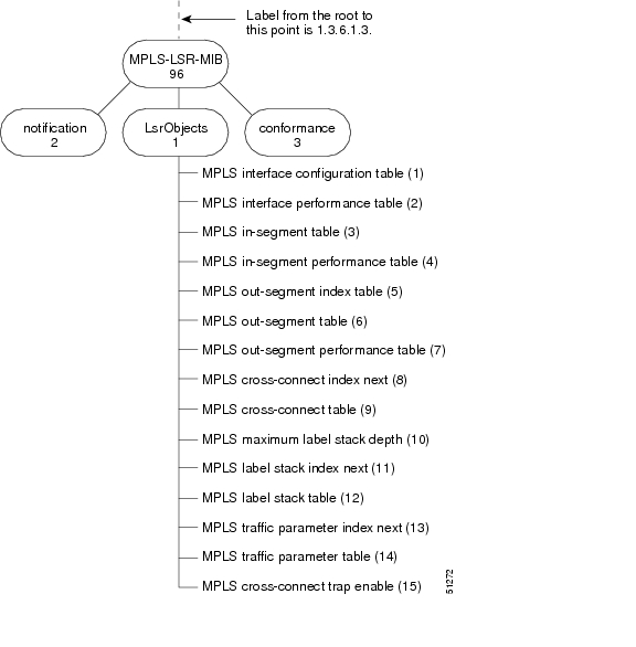
MIB structure is represented by a tree hierarchy. Branches along the tree have short text strings and integers to identify them. Text strings describe object names, and integers allow computer software to encode compact representations of the names.
The MPLS-LSR-MIB falls on the experimental branch of the Internet MIB hierarchy. The experimental branch of the Internet MIB hierarchy is represented by the object identifier 1.3.6.1.3. This branch can also be represented by its object name iso.org.dod.internet.experimental. The MPLS-LSR-MIB is identified by the object name mplsLsrMIB, which is denoted by the number 96. Therefore, objects in the MPLS-LSR-MIB can be identified in either of the following ways:
•
•
To display a MIB-variable, you enter an SNMP get command with an object identifier. Object identifiers are defined by the MPLS-LSR-MIB.
Figure 5 shows the position of the MPLS-LSR-MIB in the Internet MIB hierarchy.
Figure 5 MPLS-LSR-MIB in the Internet MIB Hierarchy
CLI Commands and the MPLS-LSR-MIB
The MPLS LFIB is the component of the Cisco MPLS subsystem that contains management information for LSRs. You can access this management information by means of either of the following:
•
•
The following examples show how you can gather LSR management information using both methods.
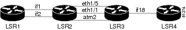
Figure 6 illustrates a simple example of an MPLS LSR topology. The output in the CLI command example and that in the MPLS-LSR-MIB command example are based on the topology shown in Figure 6.
Figure 6 Simple MPLS LSR Topology
CLI Command Output
A show mpls forwarding-table CLI command allows you to look at label forwarding information for a packet on a specific MPLS LSR.
The following partial output from a CLI command shows an incoming packet on an interface (on LSR2 in Figure 6) with a label of 1007. The packet is switched out four times to the following interfaces: Tu11 (ifindex = 20), Tu3 (ifindex = 18), Tu2 (ifindex = 17), and Tu1 (ifindex = 16).
Note
MPLS-LSR-MIB Output
SNMP commands on MIB objects also allow you to look at the label forwarding information for a specific MPLS LSR. The following example shows how the information from MIB output compares with and confirms the information from the CLI command.
You can do a walk-through of the MIB by running a command such as getmany -v2c public mplsLsrMIB on a network manager where getmany does repeated SNMP getnext operations to retrieve the contents of the MPLS-LSR-MIB. You can then scan the output, searching for those entries with an incoming label of 1007—the same label listed as the Local Tag in the CLI command output. A partial listing of the LSP output shows these four entries with the corresponding label 1007. This listing also shows the interfaces for the incoming labeled packet (on LSR2 in Figure 6). In this case, the label for the incoming interface is 3.
Note
mplsXCLspid.1664065484.3.1007.1664065484 = 0a 00 00 05mplsXCLspid.1664065628.3.1007.1664065628 = 0a 00 00 05mplsXCLspid.1664065772.3.1007.1664065772 = 0a 00 00 05mplsXCLspid.1664065916.3.1007.1664065916 = 0a 00 00 05Once you have determined the incoming interface on the packet, you can continue to scan the output of the getmany command for the following (from the MPLS out-segment table):
•
•
The entries for the outgoing segment's top label show four entries with the appropriate interfaces and label of 3. The numeral 3 denotes the use of the MPLS reserved label 3, which is represented as Untagged in the Cisco CLI output.
mplsOutSegmentTopLabel.1664065484 = 3mplsOutSegmentTopLabel.1664065628 = 3mplsOutSegmentTopLabel.1664065772 = 3mplsOutSegmentTopLabel.1664065916 = 3The MIB output shows four entries for the outgoing segment's interface index that correspond to the incoming segment's interfaces:
mplsOutSegmentIfIndex.1664065484 = 16mplsOutSegmentIfIndex.1664065628 = 17mplsOutSegmentIfIndex.1664065772 = 18mplsOutSegmentIfIndex.1664065916 = 20This output shows that the incoming interface index with a label of 3 is being swapped to outgoing interface indexes 16 (ifIndex of Tu1), 17 (ifIndex of Tu 2), 18 (ifIndex of Tu3), and 20 (ifIndex of Tu11).
Note
Benefits
The benefits described in the following paragraphs are available to you with the MPLS-LSR-MIB.
Troubleshooting LSR Problems
By monitoring the cross-connect entries and the associated incoming and outgoing segments, you can see which labels are installed and how they are being swapped. Use the MPLS-LSR-MIB in place of the show mpls forwarding CLI command.
Monitoring of LSR Traffic Loads
By monitoring interface and packet operations on an MPLS LSR, you can identify high- and low-traffic patterns, as well as traffic distributions.
Improvement of Network Performance
By identifying potentially high-traffic areas, you can set up load sharing to improve network performance.
Verification of LSR Configuration
By comparing results from SNMP get commands and the show mpls forwarding CLI command, you can verify your LSR configuration.
Displaying of Active Label Switched Paths
By monitoring the cross-connect entries and the associated incoming segments and outgoing segments, you can determine the active LSPs.
Related Documents
Cisco Documentation
For information on configuring SNMP using Cisco IOS software, see the following documents:
•
•
For information on using SNMP MIB features, see the appropriate documentation for your network management system.
Other Documentation
For information on the MPLS-LSR-MIB, see the following Internet draft documents (available at www.ietf.org):
•
•
Supported Platforms
This feature is supported on the following platforms:
•
•
•
Determining Platform Support Through Cisco Feature Navigator
Cisco IOS software is packaged in feature sets that are supported on specific platforms. To obtain updated information about platform support for this feature, access Cisco Feature Navigator. Cisco Feature Navigator dynamically updates the list of supported platforms as new platform support is added for the feature.
Cisco Feature Navigator is a web-based tool that enables you to determine which Cisco IOS software images support a specific set of features and which features are supported in a specific Cisco IOS image. You can search by feature or release. In the release section, you can compare releases side by side to display both the features unique to each software release and the features that releases have in common.
To access Cisco Feature Navigator, you must have an account on Cisco.com. If you have forgotten or lost your account information, send a blank e-mail to cco-locksmith@cisco.com. An automatic check will verify that your e-mail address is registered with Cisco.com. If the check is successful, account details with a new random password will be e-mailed to you. Qualified users can establish an account on Cisco.com by following the directions found at this URL:
Cisco Feature Navigator is updated regularly when major Cisco IOS software releases and technology releases occur. For the most current information, go to the Cisco Feature Navigator home page at the following URL:
Availability of Cisco IOS Software Images
Platform support for particular Cisco IOS software releases is dependent on the availability of the software images for those platforms. Software images for some platforms may be deferred, delayed, or changed without prior notice. For updated information about platform support and availability of software images for each Cisco IOS software release, refer to the online release notes or, if supported, Cisco Feature Navigator.
Supported Standards, MIBs, and RFCs
Standards
No new or modified standards are supported by this feature.
MIBs
MPLS Label Switching Router MIB (MPLS-LSR-MIB)
To locate and download MIBs for selected platforms, Cisco IOS releases, and feature sets, use Cisco MIB Locator found at the following URL:
http://tools.cisco.com/ITDIT/MIBS/servlet/index
If Cisco MIB Locator does not support the MIB information that you need, you can also obtain a list of supported MIBs and download MIBs from the Cisco MIBs page at the following URL:
http://www.cisco.com/public/sw-center/netmgmt/cmtk/mibs.shtml
To access Cisco MIB Locator, you must have an account on Cisco.com. If you have forgotten or lost your account information, send a blank e-mail to cco-locksmith@cisco.com. An automatic check will verify that your e-mail address is registered with Cisco.com. If the check is successful, account details with a new random password will be e-mailed to you. Qualified users can establish an account on Cisco.com by following the directions found at this URL:
RFCs
The LSR implementation supporting the MPLS-LSR-MIB is in full compliance with all provisions of Section 10 of RFC 2026.
Prerequisites
The MPLS-LSR-MIB requires the following:
•
•
•
Note
Configuration Tasks
See the following sections for configuration tasks for the MPLS-LSR-MIB feature. Each task in the list is identified as either optional or required.
•
•
Enabling the SNMP Agent
The SNMP agent for the MPLS-LSR-MIB is disabled by default. To enable the SNMP agent, perform the following steps:
:
Verifying That the SNMP Agent Has Been Enabled
To verify that the SNMP agent has been enabled, perform the following steps:
Step 1
Prompt# telnet xxx.xxx.xxx.xxxwhere xxx.xxx.xxx.xxx represents the IP address of the target device.
Step 2
Router# enableStep 3
Router# show running-configuration......snmp-server community public ROIf you see any "snmp-server" statements, SNMP has been enabled on the router.
Configuration Examples
The following example shows how to enable an SNMP agent.
Router# configure terminalRouter(config)# snmp-server communityIn the following example, SNMPv1 and SNMPv2C are enabled. The configuration permits any SNMP manager to access all objects with read-only permissions using the community string public.
Router(config)# snmp-server community publicIn the following example, read-only access is allowed for all objects to members of access list 4 that specify the comaccess community string. No other SNMP managers have access to any objects.
Router(config)# snmp-server community comaccess ro 4Command Reference
This section documents new or modified commands. All other commands used with this feature are documented in the Cisco IOS Release 12.1 and 12.2 command reference publications.
snmp-server community
To configure read-only or read-write Simple Network Management Protocol (SNMP) community strings, use the snmp-server community command in global configuration mode. To change the community string to its default value, use the no form of this command.
snmp-server community string [view view-name] [ro | rw] [number]
no snmp-server community string
Syntax Description
Defaults
The default value of the read/write parameter is read-only (ro). The default value of the read-only community string is public, and the default value of the read-write community string is private.
Command Modes
Global configuration
Command History
Usage Guidelines
The no snmp-server command disables both versions of SNMP (SNMPv1 and SNMPv2).
The first snmp-server command that you enter enables both versions of SNMP.
Examples
In this example, the read-write community string is set to newstring:
Router(config)# snmp-server community newstring rwIn the following example, the string comaccess is assigned to SNMPv1, allowing read-only access. IP access list 4 is enabled to use the community string:
Router(config)# snmp-server community comaccess ro 4In the following example, the string mgr is assigned to SNMPv1, allowing read-write access to the objects in the restricted view:
Router(config)# snmp-server community mgr view restricted rwIn the following example, the community comaccess is removed:
Router(config)# no snmp-server community comaccessIn the following example, both versions of SNMP are disabled:
Router(config)# no snmp-serverRelated Commands
snmp-server host
Specifies the recipient of an SNMP trap operation.
snmp-server enable-trap
Enables the router to send SNMP traps.
Glossary
cross-connect (XC)—An association of insegments and incoming MPLS interfaces to outsegments and outgoing MPLS interfaces.
IETF—Internet Engineering Task Force. A task force (consisting of more that 80 working groups) that is developing standards for the Internet and the IP suite of protocols.
inSegment—A label on an incoming packet that is used to determine the forwarding of the packet.
Internet Engineering Task Force—See IETF.
label—A short, fixed length identifier that is used to determine the forwarding of a packet.
Label Distribution Protocol—See LDP.
Label Forwarding Information Base—See LFIB.
label switched path—See LSP.
label switching—A term used to describe the forwarding of IP (or other network layer) packets using a label swapping algorithm based on network layer routing algorithms. The forwarding of these packets uses the exact match algorithm and rewrites the label.
label switching router—See LSR.
LDP—Label Distribution Protocol. A standard protocol between MPLS-enabled routers that is used for the negotiation of the labels (addresses) used to forward packets.
LFIB—Label Forwarding Information Base. In the Cisco MPLS subsystem, the data structure for storing information about incoming and outgoing tags (labels) and associated equivalent packets suitable for labeling.
LSP—label switched path. A sequence of hops in which a packet travels from one router to another router by means of label switching mechanisms. A label-switched path can be established dynamically, based on normal routing mechanisms, or through configuration.
LSR—label switching router. A device that forwards MPLS packets based on the value of a fixed-length label encapsulated in each packet.
Management Information Base—See MIB.
MIB—Management Information Base. Database of network management information that is used and maintained by a network management protocol such as SNMP. The value of a MIB object can be changed or retrieved by means of SNMP commands, usually through a network management system. MIB objects are organized in a tree structure that includes public (standard) and private (proprietary) branches.
MPLS—Multiprotocol Label Switching. MPLS is a method for forwarding packets (frames) through a network. It enables routers at the edge of a network to apply labels to packets (frames). ATM switches or existing routers in the network core can switch packets according to the labels with minimal lookup overhead.
MPLS interface—An interface on which MPLS traffic is enabled.
Multiprotocol Label Switching—See MPLS.
notification request—Message sent by an SNMP agent to a network management station, console, or terminal, indicating that a significant event occurred. SNMP notification requests are more reliable than traps, because a notification request from an SNMP agent requires that the SNMP manager acknowledge receipt of the notification request. The manager replies with an SNMP response protocol data unit (PDU). If the manager does not receive a notification message from an SNMP agent, it does not send a response. If the sender (SNMP agent) never receives a response, the notification request can be sent again. Thus, a notification request is more likely than a trap to reach its intended destination.
outSegment—A label on an outgoing packet.
Simple Network Management Protocol—See SNMP.
SNMP—Simple Network Management Protocol. Management protocol used almost exclusively in TCP/IP networks. SNMP provides a means for monitoring and controlling network devices, and for managing configurations, statistics collection, performance, and security.
trap—Message sent by an SNMP agent to a network management station, console, or terminal, indicating that a significant event occurred. Traps are less reliable than notification requests, because the receiver does not send an acknowledgment when it receives a trap. The sender cannot determine if the trap was received.