Feedback Feedback
|
Table Of Contents
MPLS Label Distribution Protocol MIB Version 8 Upgrade
Prerequisites for MPLS LDP MIB Version 8 Upgrade
Restrictions for MPLS LDP MIB Version 8 Upgrade
Information About the MPLS LDP MIB Version 8 Upgrade
Feature Design of the MPLS LDP MIB Version 8 Upgrade
Enhancements in Version 8 of the MPLS LDP MIB
Benefits of the MPLS LDP MIB Version 8 Upgrade
Description of MPLS LDP MIB Elements for the MPLS LDP MIB Version 8 Upgrade
Events Generating MPLS LDP MIB Notifications in the MPLS LDP MIB Version 8 Upgrade
MIB Tables in the MPLS LDP MIB Version 8 Upgrade
VPN Contexts in the MPLS LDP MIB Version 8 Upgrade
How to Configure the MPLS LDP MIB Version 8 Upgrade
Enabling Cisco Express Forwarding (CEF)
Verifying the MPLS LDP MIB Version 8 Upgrade
Configuration Examples for the MPLS LDP MIB Version 8 Upgrade
MPLS LDP MIB Version 8 Upgrade Example
MPLS Label Distribution Protocol MIB Version 8 Upgrade
The Multiprotocol Label Switching (MPLS) Label Distribution Protocol (LDP) MIB Version 8 Upgrade feature enhances the LDP MIB to support the Internet Engineering Task Force (IETF) draft version 8.
Feature History for MPLS Label Distribution Protocol MIB Version 8 Upgrade
Finding Support Information for Platforms and Cisco IOS Software Images
Use Cisco Feature Navigator to find information about platform support and Cisco IOS software image support. Access Cisco Feature Navigator at http://www.cisco.com/go/fn. You must have an account on Cisco.com. If you do not have an account or have forgotten your username or password, click Cancel at the login dialog box and follow the instructions that appear.
Contents
•
Prerequisites for MPLS LDP MIB Version 8 Upgrade
•
•
•
•
•
•
•
•
Prerequisites for MPLS LDP MIB Version 8 Upgrade
•
•
•
Restrictions for MPLS LDP MIB Version 8 Upgrade
This implementation of the MPLS LDP MIB is limited to read-only (RO) permission for MIB objects, except for MIB object mplsLdpSessionUpDownTrapEnable, which, for purposes of this release, has been extended to be writable by the SNMP agent.
Setting this object to a value of true enables both the mplsLdpSessionUp and mplsLdpSessionDown notifications on the LSR; conversely, setting this object to a value of false disables both of these notifications.
For a description of notification events, see the "Events Generating MPLS LDP MIB Notifications in the MPLS LDP MIB Version 8 Upgrade" section.
Most MPLS LDP MIB objects are set up automatically during the LDP peer discovery (hello) process and the subsequent negotiation of parameters and establishment of LDP sessions between the LDP peers.
The following tables are not implemented in this release:
•
•
•
•
•
•
•
Information About the MPLS LDP MIB Version 8 Upgrade
To configure the MPLS LDP MIB Version 8 Upgrade, you need to understand the following concepts:
•
•
•
Feature Design of the MPLS LDP MIB Version 8 Upgrade
Multiprotocol Label Switching (MPLS) is a packet forwarding technology that uses a short, fixed-length value called a label in packets to determine the next hop for packet transport through an MPLS network by means of label switch routers (LSRs).
A fundamental MPLS principle is that LSRs in an MPLS network must agree on the definition of the labels being used for packet forwarding operations. Label agreement is achieved in an MPLS network by means of procedures defined in the Label Distribution Protocol (LDP).
LDP operations begin with a discovery (hello) process during which an LDP entity (a local LSR) finds a cooperating LDP peer in the network and negotiates basic operating procedures between them. The recognition and identification of a peer by means of this discovery process results in a hello adjacency, which represents the context within which label binding information is exchanged between the local LSR and its LDP peer. LDP functionality then creates an active LDP session between the two LSRs to effect the exchange of label binding information. The result of this process, when carried to completion with respect to all the LSRs in an MPLS network, is a label-switched path (LSP), which constitutes an end-to-end packet transmission pathway between the communicating network devices.
By means of LDP, LSRs can collect, distribute, and release label binding information to other LSRs in an MPLS network, thereby enabling the hop-by-hop forwarding of packets in the network along normally routed paths.
The MPLS LDP MIB has been implemented to enable standard, SNMP-based network management of the label switching features in Cisco IOS. Providing this capability requires SNMP agent code to execute on a designated network management station (NMS) in the network. The NMS serves as the medium for user interaction with the network management objects in the MPLS LDP MIB.
The SNMP agent embodies a layered structure that is compatible with Cisco IOS and presents a network administrative and management interface to the objects in the MPLS LDP MIB and, thence, to the rich set of label switching capabilities supported by Cisco IOS.
By means of an SNMP agent, you can access MPLS LDP MIB objects using standard SNMP GET operations to accomplish a variety of network management tasks. All the objects in the MPLS LDP MIB follow the conventions defined in the IETF draft MIB entitled draft-ietf-mpls-ldp-mib-08.txt, which defines network management objects in a structured and standardized manner. This draft MIB is continually being evolved toward the status of a standard. Accordingly, the MPLS LDP MIB will be implemented in a manner that tracks the evolution of this IETF document.
Slight differences that exist between the IETF draft MIB and the implementation of equivalent functions in Cisco IOS require some minor translations between the MPLS LDP MIB objects and the internal data structures of Cisco IOS. Such translations are accomplished by the SNMP agent, which runs in the background on the NMS workstation as a low priority process.
The extensive label switching capabilities supported in Cisco IOS provide an integrated approach to managing the large volumes of traffic carried by WANs. These capabilities are integrated into the Layer 3 network services, thus optimizing the routing of high-volume traffic through Internet service provider backbones while, at the same time, ensuring the resiliency of the network to link or node failures.
This release of Cisco IOS supports the following functionality in relation to the MPLS LDP MIB:
•
•
•
•
•
The structure of the MPLS LDP MIB conforms to Abstract Syntax Notation One (ASN.1), thereby forming a highly structured and idealized database of network management objects.
Using any standard SNMP application, you can retrieve and display information from the MPLS LDP MIB by means of standard SNMP GET operations; similarly, you can traverse and display information in the MIB by means of SNMP GETNEXT operations.
Note
ciscoExperimental 1.3.6.1.4.1.9.10
mplsLdpMIB 1.3.6.1.4.1.9.10.65
If the MPLS LDP MIB is assigned an IANA Experimental OID number, Cisco will replace all objects in the MIB under the ciscoExperimental OID and reposition the objects under the IANA Experimental OID.
Enhancements in Version 8 of the MPLS LDP MIB
Version 8 of the MPLS LDP MIB contains the following enhancements since the release of Version 1:
•
•
•
Benefits of the MPLS LDP MIB Version 8 Upgrade
•
•
•
–
–
–
–
–
–
•
•
•
–
–
–
–
•
–
–
–
–
–
–
Description of MPLS LDP MIB Elements for the MPLS LDP MIB Version 8 Upgrade
LDP operations related to an MPLS LDP MIB involve the following functional elements:
•
•
•
•
These MPLS LDP MIB elements are briefly described under separate headings below.
In effect, the MPLS LDP MIB provides a network management database that supports real-time access to the various MIB objects within, reflecting the current state of MPLS LDP operations in the network. This network management information database is accessible by means of standard SNMP commands issued from an NMS in the MPLS LDP operating environment.
The MPLS LDP MIB supports the following network management and administrative activities:
•
•
•
•
•
LDP Entities
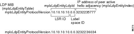
An LDP entity is uniquely identified by an LDP identifier that consists of the mplsLdpEntityLdpId and the mplsLdpEntityIndex as shown in Figure 1. The mplsLdpEntityLdpId consists of the local LSR ID (four octets) and the label space ID (two octets). The mplsLdpEntityIndex consists of the IP address of the peer active hello adjacency, which is the 32-bit representation of the IP address assigned to the peer LSR. The label space ID identifies a specific label space available within the LSR.
The mplsldpEntityProtocolVersion is a sample object from the mplsLdpEntityTable.
Figure 1 shows the following indexing:
•
•
•
The mplsLdpEntityLdpId or the LDP ID consists of the LSR ID and the label space ID.
•
Figure 1 Sample Indexing for an LDP Entity
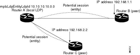
An LDP entity represents a label space that has the potential for a session with an LDP peer. An LDP entity is set up when a hello adjacency receives a hello message from an LDP peer.
In Figure 2, Router A has potential sessions with two remote peers, Routers B and C. The mplsLdpEntityLdpId = 10.10.10.10.0.0, and the IP address of the peer active hello adjacency (mplsLdpEntityIndex) = 3232235777, which is the 32-bit representation of the IP address 192.168.1.1 for Router B.
Figure 2
LDP Entity
LDP Sessions and Peers
LDP sessions exist between local entities and remote peers for the purpose of distributing label spaces. There is always a one-to-one correspondence between an LDP peer and an LDP session. A single LDP session is a label distribution protocol instance that communicates across one or more network links with a single LDP peer.
LDP supports the following types of sessions:
•
•
When a session is established between two peers, entries are created in the mplsLdpPeerTable and the mplsLdpSessionTable because they have the same indexing.
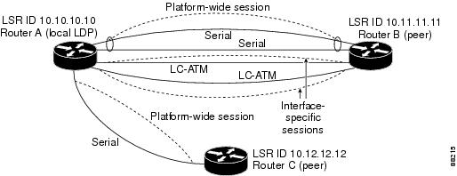
In Figure 3, Router A has two remote peers, Routers B and C. Router A has a single platform-wide session that consists of two serial interfaces with Router B and another platform-wide session with Router C. Router A also has two interface-specific sessions with Router B.
Figure 3
LDP Session
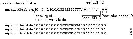
Figure 4 shows entries that correspond to the mplsLdpPeerTable and the mplsLdpSessionTable in Figure 3.
In Figure 4, mplsLdpSesState is a sample object from the mplsLdpSessionTable on Router A. There are four mplsLdpSesState sample objects shown (top to bottom). The first object represents a platform-wide session associated with two serial interfaces. The next two objects represent interface-specific sessions for the LC-ATM interfaces on Routers A and B. Note that these interface-specific sessions have non-zero peer label space IDs. The last object represents a platform-wide session for the next peer, Router C.
The indexing is based on the entries in the mplsLdpEntityTable. It begins with the indexes of the mplsLdpEntityTable and adds the following:
•
The peer LDP ID consists of the peer LSR ID (four octets) and the peer label space ID (two octets).
•
•
The peer label space ID identifies a specific peer label space available within the LSR.
Figure 4
Sample Indexing for an LDP Session
LDP Hello Adjacencies
An LDP hello adjacency is a network link between a router and its peers. The purpose of an LDP hello adjacency is to exchange label binding information between two LSRs that are adjacent to each other in a network.
An LDP hello adjacency exists for each link on which LDP runs. Multiple LDP hello adjacencies exist whenever there is more than one link in a session between a router and its peer, such as in a platform-wide session.
A hello adjacency is considered active if it is currently engaged in a session, or nonactive if it is not currently engaged in a session.
A targeted hello adjacency is not directly connected to its peer and has an unlimited number of hops between itself and its peer. A linked hello adjacency is directly connected between two routers.
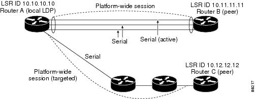
In Figure 5, Router A has two remote peers, Routers B and C. Router A has a platform-wide session that consists of three serial interfaces, one of which is active, with Router B and another platform-wide (targeted) session with Router C.
Figure 5
Hello Adjacency
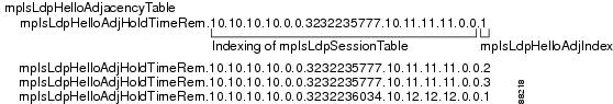
Figure 6 shows entries in the mplsLdpHelloAdjacencyTable. There are four
mplsLdpHelloAdjHoldTime sample objects (top to bottom). They represent the two platform-wide sessions and the four serial links shown in Figure 5.The indexing is based on the mplsLdpSessionTable. When the mplsLdpHelloAdjIndex enumerates the different links within a single session, the active link is mplsLdpHelloAdjIndex = 1.
Figure 6
Sample Indexing for an LDP Hello Adjacency
Events Generating MPLS LDP MIB Notifications in the MPLS LDP MIB Version 8 Upgrade
When you enable MPLS LDP MIB notification functionality by issuing the snmp-server enable traps mpls ldp command, notification messages are generated and sent to a designated NMS in the network to signal the occurrence of specific events within Cisco IOS.
The MPLS LDP MIB objects involved in LDP status transitions and event notifications include the following:
•
•
•
The value of the path vector limit can range from 0 through 255; a value of 0 indicates that loop detection is off; any value other than zero up to 255 indicates that loop detection is on and, in addition, specifies the maximum number of hops through which an LDP message can pass before a loop condition in the network is sensed.
We recommend that all LDP-enabled routers in the network be configured with the same path vector limit. Accordingly, the mplsLdpPathVectorLimitMismatch object exists in the MPLS LDP MIB to provide a warning message to the NMS when two routers engaged in LDP operations have a dissimilar path vector limit.
Note
•
Eight failed attempts to establish an LDP session between a local LSR and an LDP peer, due to any type of incompatibility between the devices, causes this notification message to be generated.
In general, Cisco routers support the same features across multiple platforms. Therefore, the most likely incompatibility to occur between Cisco LSRs is a mismatch of their respective ATM VPI/VCI label ranges.
For example, if you specify a range of valid labels for an LSR that does not overlap the range of its adjacent LDP peer, the routers will try eight times to create an LDP session between themselves before the mplsLdpFailedInitSessionThresholdExceeded notification is generated and sent to the NMS as an informational message.
Operationally, the LSRs whose label ranges do not overlap continue their attempt to create an LDP session between themselves after the eight retry threshold is exceeded. In such cases, the LDP threshold exceeded notification alerts the network administrator to the existence of a condition in the network that may warrant attention.
RFC 3036, LDP Specification, details the incompatibilities that can exist between Cisco routers and/or other vendor LSRs in an MPLS network. Among such incompatibilities, for example, are the following:
–
–
–
–
MIB Tables in the MPLS LDP MIB Version 8 Upgrade
The MPLS LDP MIB consists of the following tables:
•
The advantage of showing the active hello adjacency in this table instead of sessions is that the active hello adjacency can exist even if an LDP session is not active (cannot be established). Previous implementations of the IETF MPLS-LDP MIB used sessions as the entries in this table. This approach was inadequate because as sessions went down, the entries in the entity table would disappear completely because the agent code could no longer access them. This resulted in the MIB failing to provide information about failed LDP sessions.
Directed adjacencies are also shown in this table. These entries, however, are always administratively (adminStatus) and operationally (operStatus) up because the adjacencies disappear if the directed session were to fail. Nondirected adjacencies may disappear from the MIB on some occasions as well because adjacencies are deleted if the underlying interface becomes operationally down, for example.
•
•
•
•
•
•
•
•
•
mplsLdpEntityTable
Table 1 lists the mplsLdpEntityTable objects and their descriptions.
mplsLdpEntityConfGenLRTable
Table 2 lists the mplsLdpEntityConfGenLRTable objects and their descriptions.
mplsLdpEntityAtmParmsTable
Table 3 lists the mplsLdpEntityAtmParmsTable objects and their descriptions.
mplsLdpEntityConfAtmLRTable
Table 4 lists the mplsLdpEntityConfAtmLRTable objects and their descriptions.
mplsLdpEntityStatsTable
Table 5 lists the mplsLdpEntityStatsTable objects and their descriptions.
mplsLdpPeerTable
Table 6 lists the mplsLdpPeerTable objects and their descriptions.
mplsLdpHelloAdjacencyTable
Table 7 lists the mplsLdpHelloAdjacencyTable objects and their descriptions.
mplsLdpSessionTable
Table 8 lists the mplsLdpSessionTable objects and their descriptions.
mplsLdpAtmSesTable
Table 9 lists the mplsLdpAtmSesTable objects and their descriptions.
mplsLdpSesStatsTable
Table 10 lists the mplsLdpSesStatsTable objects and their descriptions.
VPN Contexts in the MPLS LDP MIB Version 8 Upgrade
Within an MPLS Border Gateway Protocol (BGP) 4 Virtual Private Network (VPN) environment, separate LDP processes can be created for each VPN. These processes and their associated data are called VPN contexts. Each context is independent from all others and contains data specific only to that context. The IETF MPLS-LDP MIB is capable only of showing information about a single context at one time.
Note
How to Configure the MPLS LDP MIB Version 8 Upgrade
This section contains the following procedures:
•
•
•
•
•
•
•
Enabling the SNMP Agent
Perform this task to enable the SNMP agent.
SUMMARY STEPS
1.
2.
3.
4.
5.
6.
DETAILED STEPS
Enabling Cisco Express Forwarding (CEF)
Perform this task to enable CEF.
SUMMARY STEPS
1.
2.
3.
4.
DETAILED STEPS
Enabling MPLS Globally
Perform this task to enable MPLS globally.
SUMMARY STEPS
1.
2.
3.
4.
DETAILED STEPS
Enabling LDP Globally
Perform this task to enable LDP globally.
SUMMARY STEPS
1.
2.
3.
4.
DETAILED STEPS
Enabling MPLS on an Interface
Perform this task to enable MPLS on an interface.
SUMMARY STEPS
1.
2.
3.
4.
5.
DETAILED STEPS
Enabling LDP on an Interface
Perform this task to enable LDP on an interface.
SUMMARY STEPS
1.
2.
3.
4.
5.
DETAILED STEPS
Verifying the MPLS LDP MIB Version 8 Upgrade
Perform a MIB walk using your SNMP management tool to verify that the MPLS LDP MIB Version 8 Upgrade feature is functioning.
Note
Configuration Examples for the MPLS LDP MIB Version 8 Upgrade
This section provides the following configuration examples:
•
MPLS LDP MIB Version 8 Upgrade Example
The following example shows how to enable an SNMP agent on the host NMS:
Router# configure terminalEnter configuration commands, one per line. End with CNTL/Z.Router(config)# snmp-server communityThe following example shows how to enable SNMPv1 and SNMPv2C on the host NMS. The configuration permits any SNMP agent to access all MPLS LDP MIB objects with read-only permission using the community string public.
Router(config)# snmp-server community publicThe following example shows how to allow read-only access to all MPLS LDP MIB objects relating to members of access list 4 that specify the comaccess community string. No other SNMP agents will have access to any of the MPLS LDP MIB objects.
Router(config)# snmp-server community comaccess ro 4The following example shows how to enable LDP globally and then on an interface:
Router# configure terminalEnter configuration commands, one per line. End with CNTL/Z.Router(config)# mpls label protocol ldpRouter(config)# interface Ethernet1Router(config-if)# mpls label protocol ldpRouter(config-if)# endAdditional References
The following sections provide references related to the MPLS LDP MIB Version 8 Upgrade feature:
•
•
Related Documents
Standards
No new or modified standards are supported by this feature, and support for existing standards has not been modified by this feature.
—
MIBs
RFCs
Technical Assistance
Command Reference
This section documents new or modified commands. All other commands used with this feature are documented in the Cisco IOS Release 12.2 command reference publications.
snmp-server community
To configure read-only Simple Network Management Protocol (SNMP) community strings for the MPLS LDP MIB, use the snmp-server community command in global configuration mode on the host network management station (NMS). To change the community string to its default value, use the no form of this command.
snmp-server community string [view view-name] [ro] [number]
no snmp-server community string
Syntax Description
Defaults
The default value of the read/write keyword is read-only (ro).
The default value of the read-only community string is public.
The default value of the read/write community string is private.
Command Modes
Global configuration
Command History
Usage Guidelines
The no snmp-server command disables both SNMPv1 and SNMPv2.
The first snmp-server command issued enables both SNMPv1 and SNMPv2.
Examples
The following example shows how to set the read/write community string to newstring:
Router(config)# snmp-server community newstring rwThe following example shows how to assign the string comaccess to SNMPv1, allowing read-only access and specifying that IP access list 4 can use the community string:
Router(config)# snmp-server community comaccess ro 4The following example shows how to assign the string mgr to SNMPv1, allowing read/write access to the objects in the restricted view:
Router(config)# snmp-server community mgr view restricted rwThe following example shows how to remove the community string comaccess.
Router(config)# no snmp-server community comaccessThe following example shows how to disable both SNMP versions:
Router(config)# no snmp-serverRelated Commands
Enables an MPLS LSR to send SNMP notification messages to a designated NMS workstation in an MPLS network.
Specifies the targeted recipient of an SNMP notification message.
snmp-server enable traps
To enable a label switch router (LSR) to send Simple Network Management Protocol (SNMP) notifications or informs to an SNMP host, use the snmp-server enable traps command in global configuration mode. To disable notifications or informs, use the no form of this command.
snmp-server enable traps [notification-type] [notification-option]
no snmp-server enable traps [notification-type] [notification-option]
Syntax Description
Defaults
If you issue this command on an LSR without specifying any notification-type keywords, the default behavior of the LSR is to enable all notification types controlled by the command (some notification types cannot be controlled by means of this command).
Command Modes
Global configuration
Command History
Usage Guidelines
To configure an LSR to send SNMP LDP notifications, you must issue at least one snmp-server enable traps command on the router.
To configure an LSR to send either notifications (traps) or informs to a designated NMS, you must issue the snmp-server host command on that device using the desired keyword (traps or informs) that suits your purposes.
If you issue the snmp-server enable traps command without keywords, all SNMP notification types are enabled on the LSR. If you issue this command with specific keywords, only the notification types associated with those particular keywords are enabled on the LSR.
The snmp-server enable traps command is used in conjunction with the snmp-server host command. You use the latter command to specify the NMS host (or hosts) targeted as the recipient(s) of the SNMP notifications generated by SNMP-enabled LSRs in the network. To enable an LSR to send such notifications, you must issue at least one snmp-server host command on the LSR.
Examples
In the following example, the router is enabled to send all notifications to the host specified as myhost.cisco.com, using the community string defined as public:
Router(config)# snmp-server enable trapsRouter(config)# snmp-server host myhost.cisco.com publicIn the following example, the router is enabled to send Frame Relay and environmental monitor notifications to the host specified as myhost.cisco.com using the community string public:
Router(config)# snmp-server enable traps frame-relayRouter(config)# snmp-server enable traps envmon temperatureRouter(config)# snmp-server host myhost.cisco.com publicIn the following example, notifications are not sent to any host. BGP notifications are enabled for all hosts, but the only notifications enabled to be sent to a host are ISDN notifications (which are not enabled in this example).
Router(config)# snmp-server enable traps bgpRouter(config)# snmp-server host bob public isdnIn the following example, the router is enabled to send all inform requests to the host specified as myhost.cisco.com, using the community string defined as public:
Router(config)# snmp-server enable trapsRouter(config)# snmp-server host myhost.cisco.com informs version 2c publicIn the following example, HSRP MIB notifications are sent to the host specified as myhost.cisco.com using the community string public:
Router(config)# snmp-server enable hsrpRouter(config)# snmp-server host myhost.cisco.com traps version 2c public hsrpRelated Commands
Specifies the intended recipient of an SNMP notification (that is, the designated NMS workstation in the network).
snmp-server host
To specify a network management station (NMS) in the network as the intended recipient of Simple Network Management Protocol (SNMP) notifications or informs, use the snmp-server host command in global configuration mode. To disable the configuration of the NMS as an SNMP host, use the no form of this command.
snmp-server host host-addr [traps | informs] [version {1 | 2c | 3 [auth | noauth | priv]}] community-string [udp-port port] [notification-type]
no snmp-server host host-addr [traps | informs]
Syntax Description
host-addr
Specifies the name or the IP address of the host NMS workstation on which the SNMP agent is running (thus serving as the recipient of SNMP notifications or informs).
traps
(Optional) Sends SNMP notifications to the specified NMS host. This is the default assumption of the snmp-server host command.
informs
(Optional) Sends SNMP informs to the specified NMS host.
version
(Optional) Indicates the SNMP version to be used in sending LDP notifications or informs to the NMS host. Version 3 is most secure, because it allows packet encryption by means of the priv keyword (below). If you use the version keyword, you must also specify one of the following arguments:
•
•
•
–
–
–
community-string
The community string, functioning much like a password, is sent with the notification or informs operation. Although you can set this string using the snmp-server host command by itself, we recommend that you define this string using the snmp-server community command prior to using the snmp-server host command.
udp-port port
User Datagram Protocol (UDP) port number of the NMS host to which SNMP notifications or informs are to be sent. The default UDP port number is 162.
notification-type
(Optional) Specifies the particular type of SNMP notifications or informs to be sent to the NMS host. If no notification type is specified, all applicable SNMP notifications or informs are sent. Any one or more of the following can be specified as a keyword in this command:
•
•
•
•
•
•
•
•
•
•
•
•
•
•
•
•
•
•
•
•
•
•
Defaults
This command is disabled by default, in which case, no SNMP notifications are sent.
If you enter this command without keywords, the default is to send all notification types to the NMS host. No informs will be sent to the host.
If no version keyword is specified, the default is version 1. Issuing the no snmp-server host command without keywords disables notifications, but not informs, to the NMS host. To disable informs, use the no snmp-server host informs command.
Note
Command Modes
Global configuration
Command History
Usage Guidelines
To configure a label switch router (LSR) to send SNMP notifications to an NMS, you must enter at least one snmp-server host command on the LSR.
If you issue the snmp-server host command without keywords, all SNMP notification types are enabled for the specified NMS host. If you issue this command with specific keywords, only the notification types associated with those particular keywords are enabled for the NMS host.
To enable multiple NMS hosts, you must issue a separate snmp-server host command for each targeted NMS host. You can specify multiple notification types in the command for each NMS.
When multiple snmp-server host commands are issued for the same NMS host and notification type (trap or inform request), each succeeding such command issued overwrites the previous command. For example, if you issue an snmp-server host inform command for an NMS host, and then issue another snmp-server host inform command for the same NMS host, the second command overrides the first command.
The snmp-server host command is used in conjunction with the snmp-server enable command. You use the snmp-server enable command to specify which SNMP notifications are to be sent globally. For an NMS host to receive most SNMP notifications, at lease one snmp-server enable command and the snmp-server host command for that NMS host must be enabled on the LSR.
Examples
If you want to configure a unique SNMP community string for notifications, but you want to prevent SNMP polling access with this particular string, the configuration should include an access-list. In the following example, the community string is named comaccess and the access list is numbered 10:
Router(config)# snmp-server community comaccess ro 10Router(config)# snmp-server host 172.20.2.160 comaccessRouter(config)# access-list 10 deny anyIn the following example, SNMP notifications are sent to the NMS host specified as myhost.cisco.com. The community string is defined as comaccess.
Router(config)# snmp-server enable trapsRouter(config)# snmp-server host myhost.cisco.com comaccess snmpIn the following example, SNMP and the Cisco environmental monitor (envmon) enterprise-specific notifications are sent to the NMS host identified by IP address 172.30.2.160:
Router(config)# snmp-server enable trapsRouter(config)# snmp-server host 172.30.2.160 public snmp envmonIn the following example, the LSR is enabled to send all notifications to the SNMP host identified as myhost.cisco.com using the community string public:
Router(config)# snmp-server enable trapsRouter(config)# snmp-server host myhost.cisco.com publicIn the following example, notifications will not be sent to any SNMP host. The BGP notifications are enabled for all hosts, but only the ISDN notifications are enabled for sending to the host NMS.
Router(config)# snmp-server enable traps bgpRouter(config)# snmp-server host bob public isdnIn the following example, the LSR is enabled to send all inform requests to the NMS host specified as myhost.cisco.com using the community string public:
Router(config)# snmp-server enable trapsRouter(config)# snmp-server host myhost.cisco.com informs version 2c publicIn the following example, HSRP MIB notifications are sent to the NMS host specified as myhost.cisco.com. The community string is defined as public.
Router(config)# snmp-server enable hsrpRouter(config)# snmp-server host myhost.cisco.com traps version 2c public hsrpRelated Commands
Enables the LSR on which this command is executed to send SNMP notifications to a designated NMS host.
Glossary
ATM—Asynchronous Transfer Mode. The international standard for cell relay in which multiple service types (such as voice, video, or data) are conveyed in fixed-length (53-byte) cells. Fixed-length cells allow cell processing to occur in hardware, thereby reducing transit delays. ATM is designed to take advantage of high-speed transmission media, such as E3, SONET, and T3.
informs—A type of notification message that is more reliable than a conventional trap notification message, because the informs message notification requires acknowledgment, while a trap notification does not.
label—A short, fixed-length data identifier that tells switching nodes how to forward data (packets or cells).
label distribution—The techniques and processes used to cause routed traffic to travel through the network on a path other than the one that would have been chosen if standard routing methods had been used.
LDP—Label Distribution Protocol. The protocol that supports MPLS hop-by-hop forwarding by distributing bindings between labels and network prefixes. The Cisco proprietary version of this protocol is the Tag Distribution Protocol (TDP).
LSP—label-switched path. A configured connection between two label switch routers (LSRs) in which label-switching techniques are used for packet forwarding; a specific path through an MPLS network.
LSR—label switch router. A Multiprotocol Label Switching (MPLS) node that can forward native Layer 3 packets. The LSR forwards a packet based on the value of a label attached to the packet.
MIB—Management Information Base. A database of network management information that is used and maintained by a network management protocol such as Simple Network Management Protocol (SNMP). The value of a MIB object can be changed or retrieved by using SNMP commands, usually through a network management system. MIB objects are organized in a tree structure that includes public (standard) and private (proprietary) branches.
MPLS—Multiprotocol Label Switching. A switching method that forwards IP traffic using a label. This label instructs the routers and the switches in the network where to forward the packets based on preestablished IP routing information.
MPLS label distribution—A constraint-based routing algorithm for routing label-switched path (LSP) tunnels.
NMS—network management station. A powerful, well-equipped computer (typically an engineering workstation) that is used by a network administrator to communicate with other devices in the network. An NMS is typically used to manage network resources, gather statistics, and perform a variety of network administration and configuration tasks.
notification—A message sent by a Simple Network Management Protocol (SNMP) agent to a network management station, console, or terminal to indicate that a significant event within Cisco IOS has occurred. See also trap.
RSVP—Resource Reservation Protocol. A protocol that supports the reservation of resources across an IP network. Applications running on IP end systems can use RSVP to indicate to other nodes the nature (bandwidth, jitter, maximum burst, and so on) of the packet streams they want to receive.
SNMP—Simple Network Management Protocol. A network management protocol used almost exclusively in TCP/IP networks. SNMP provides a means to monitor and control network devices, manage configurations, collect statistics, monitor performance, and ensure network security.
TDP—Tag Distribution Protocol. A standard protocol between MPLS-enabled routers to negotiate the tags (addresses) used to forward packets. See also LDP.
TLV—Type-Length-Value. A block of information embedded in Cisco Discovery Protocol (CDP) advertisements.
trap—A message sent by an SNMP agent to a network management station, console, or terminal to indicate that a significant event within Cisco IOS has occurred. Traps (notifications) are less reliable than inform requests, because the receiver of the trap does not send an acknowledgment of receipt; furthermore, the sender of the trap cannot determine if the trap was received. See also notification.
VCC—virtual channel connection. A logical circuit, made up of virtual channel links (VCLs), that carries data between two endpoints in an ATM network. Sometimes called a virtual circuit connection.
VCI—virtual channel identifier. A 16-bit field in the header of an ATM cell. The VCI, together with the virtual path identifier (VPI), is used to identify the next network virtual channel link (VCL) as the cell passes through a series of ATM switches on its way to its final destination.
VCL—virtual channel link. The logical connection that exists between two adjacent switches in an ATM network.
VPI—virtual path identifier. An 8-bit field in the header of an ATM cell. The VPI, together with the virtual channel identifier (VCI), is used to identify the next network virtual channel link (VCL) as the cell passes through a series of ATM switches on its way to its final destination.
VPN—Virtual Private Network. A network that enables IP traffic to use tunneling to travel securely over a public TCP/IP network.
Note
Copyright © 2003 Cisco Systems, Inc. All rights reserved.