Downloads |
 Feedback Feedback
|
Table Of Contents
MPLS Enhancements to Interfaces MIB
Stacking Relationships for MPLS Layer Interfaces
Stacking Relationships for Traffic Engineering Tunnels
MPLS Label Switching Router MIB Enhancements
Supported Standards, MIBs, and RFCs
Verifying That the SNMP Agent Has Been Enabled
MPLS Enhancements to Interfaces MIB
Feature History
12.0(23)S
This feature was introduced.
12.2(18)S
This feature was integrated into Cisco IOS Release 12.2(18)S.
This document describes the Multiprotocol Label Switching (MPLS) enhancements to the existing interfaces Management Information Base (MIB) (RFC 2233) to support an MPLS layer. This layer provides counters and statistics specifically for MPLS.
This document includes the following major sections:
•
Supported Standards, MIBs, and RFCs
Feature Overview
The Interfaces MIB (IF MIB) provides a Simple Network Management Protocol (SNMP)-based method for managing interfaces. Each entry in the IF MIB establishes indexing, statistics, and stacking relationships among underlying physical interfaces, subinterfaces, and Layer 2 protocols that exist within Cisco IOS.
The enhancements add an MPLS layer to the IF MIB as a Layer 2 protocol to provide statistics for traffic encapsulated as MPLS on an interface. In this new structure, MPLS-specific data, such as MPLS-encapsulated traffic counters and the MPLS maximum transmission unit (MTU), resides on top of the underlying physical or virtual interface to allow separation from non-MPLS data.
The enhancements also allow you to view indexing, statistics, and stacking relationships using the ifStackTable. MPLS layer interfaces are stacked above the underlying physical or virtual interface that is actually forwarding the MPLS traffic. MPLS traffic engineering tunnels are then stacked above those MPLS layers.
The IF MIB supports several types of interfaces. A virtual interface that provides protocol statistics for MPLS-encapsulated traffic has been added. This new interface is stacked above real Cisco IOS interfaces or subinterfaces, such as Ethernet (et0) or ATM (at1/1.1).
Cisco IOS creates a corresponding MPLS layer above each interface capable of supporting MPLS when the MPLS encapsulation is enabled by issuing the interface configuration command mpls ip.
You can also create the interface layer if you enable MPLS traffic engineering (TE) by using the interface command mpls traffic-eng tunnels.
Note
An IF MIB entry is created when you enable either MPLS IP and/or MPLS TE tunnels on an interface; the entry is removed when you disable both MPLS IP and MPLS TE.
MIB Tables
The IF MIB consists of the following tables:
•
•
•
•
Note
The notation used in the IF MIB follows the conventions defined in Abstract System Notation One (ASN.1). ASN.1 defines an Open System Interconnection (OSI) language used to describe data types independently from particular computer structures and presentation techniques. Each object in the MIB incorporates a DESCRIPTION field that includes an explanation of the object's meaning and usage, which, together with the other characteristics of the object (SYNTAX, MAX-ACCESS, and INDEX) provides sufficient information for management application development, as well as for documentation and testing.
A network administrator can access the entries (objects) in the IF MIB by means of any SNMP-based network management system (NMS). The network administrator can retrieve information in the IF MIB using standard SNMP GET and GETNEXT operations.
ifTable Objects
Table 1 lists the ifTable objects and their descriptions.
ifXTable Objects
Table 2 lists the ifXTable objects and their descriptions.
Note
ifStackTable Objects
Table 3 lists the ifStackTable objects and their descriptions.
ifRcvAddressTable Objects
Table 4 lists the ifRcvAddressTable objects and their descriptions.
Note
Scalar Objects
The IF MIB supports the following scalar objects:
•
•
Stacking Relationships for MPLS Layer Interfaces
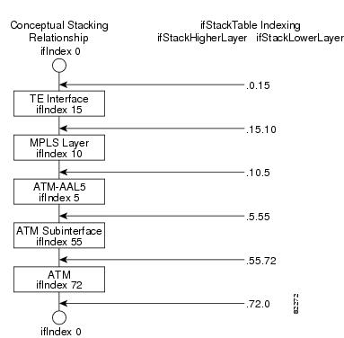
The ifStackTable within the IF MIB provides a conceptual stacking relationship between the interfaces and subinterfaces represented as entries in the ifTable.
The ifStackTable is indexed like a linked list. Each entry shows a relationship between two interfaces providing the ifIndexes of the upper and the lower interface. The entries chain together to show the entire stacking relationship. Each entry links with one another until the stack terminates with an ifIndex of 0 at the highest and lowest ends of the stack. For example, in Figure 1, the indexes .10.5 show that ifIndex 10 is stacked upon ifIndex 5. There are 0 entries at the highest and lowest ends of the stack; in Figure 1, the indexes .0.15 and .72.0 are the highest and lowest ends of the stack, respectively.
Figure 1 Sample ATM Stacking Relationship in the ifStackTable
Table 5 describes the indexing of the ifStackTable for the layer relationships shown in Figure 1.
Note
Stacking Relationships for Traffic Engineering Tunnels
MPLS traffic engineering (TE) tunnels are represented in Cisco IOS and the IF MIB as virtual interfaces. When properly signaled, TE tunnels pass traffic through MPLS over a physical interface. This process dictates that a TE tunnel is to be stacked on an MPLS layer that is stacked on an underlying interface.
TE tunnels can also change paths in response to different error or network conditions. These changes are instigated by using the RSVP-TE signaling protocol. When a change occurs, a tunnel can switch to a different MPLS interface. If no signaling path exists, no paths will be chosen and thus no MPLS interface will be used.
Because a TE tunnel is represented as an IF MIB ifTable entry, the ifStackTable also contains an entry corresponding to the TE tunnel. If the TE tunnel is successfully signaled, the ifStackTable also contains a link between the tunnel interface as well as one MPLS interface. Note that because it is possible for a TE tunnel to not have a corresponding signaled path, it is thus possible for a TE tunnel's ifStackTable entry to not have a corresponding lower layer. In this case, the lower layer variable contains the value of 0.
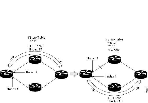
Figure 2 shows a TE tunnel before (left) and after (right) being rerouted and the affect on the ifStackTable. When ifIndex 2 fails, the TE tunnel is rerouted through ifIndex1, the 15.2 entry is removed from the ifStackTable, and the 15.1 entry is added.
Figure 2
Sample TE Tunnel Stacking Relationship
MPLS Label Switching Router MIB Enhancements
All of the ifIndex references in the MPLS-LSR-MIB tables have changed from the ifIndex of the underlying physical or virtual interface to the ifIndex of the MPLS layer.
Table 6 shows the specific changes.
The following objects from the mplsInterfaceConfTable are affected:
•
•
Benefits
Improved Accounting Capability
By viewing the MPLS layer, you get MPLS-encapsulated traffic counters that do not include non-MPLS encapsulated traffic (for example, IP packets). Therefore, the counters are more useful for MPLS-related statistics.
TE Tunnel Interfaces
For TE tunnel interfaces, the stacking relationship reflects the current underlying MPLS interface that is in use and dynamically changes as TE tunnels reoptimize and reroute.
MPLS-Specific Information
The MPLS layer shows MPLS-specific information including the following:
•
•
•
•
Restrictions
•
•
•
Related Documents
Cisco Documentation
For information on configuring SNMP using Cisco IOS software, see the following documents:
•
•
•
Other Documentation
•
For information on using SNMP MIB features, see the appropriate documentation for your network management system.
Supported Platforms
•
•
•
Finding Support Information for Platforms and Cisco IOS Software Images
Use Cisco Feature Navigator to find information about platform support and Cisco IOS software image support. Access Cisco Feature Navigator at http://www.cisco.com/go/fn. You must have an account on Cisco.com. If you do not have an account or have forgotten your username or password, click Cancel at the login dialog box and follow the instructions that appear.
Supported Standards, MIBs, and RFCs
Standards
No new or modified standards are supported by this feature.
MIBs
Interfaces Group MIB (IF MIB)
To locate and download MIBs for selected platforms, Cisco IOS releases, and feature sets, use Cisco MIB Locator found at the following URL:
http://tools.cisco.com/ITDIT/MIBS/servlet/index
If Cisco MIB Locator does not support the MIB information that you need, you can also obtain a list of supported MIBs and download MIBs from the Cisco MIBs page at the following URL:
http://www.cisco.com/public/sw-center/netmgmt/cmtk/mibs.shtml
To access Cisco MIB Locator, you must have an account on Cisco.com. If you have forgotten or lost your account information, send a blank e-mail to cco-locksmith@cisco.com. An automatic check will verify that your e-mail address is registered with Cisco.com. If the check is successful, account details with a new random password will be e-mailed to you. Qualified users can establish an account on Cisco.com by following the directions found at this URL:
RFCs
•
•
•
•
•
Prerequisites
The MPLS Enhancements to Interfaces MIB feature requires the following:
•
•
•
Configuration Tasks
See the following sections for configuration tasks for the MPLS Enhancements to Interfaces MIB feature. Each task in the list is identified as either optional or required.
•
•
Enabling the SNMP Agent
The SNMP agent for the IF MIB is disabled by default. To enable the SNMP agent, use the following commands:
:
Verifying That the SNMP Agent Has Been Enabled
To verify that the SNMP agent has been enabled, perform the following steps:
Step 1
Prompt# telnet xxx.xxx.xxx.xxxwhere xxx.xxx.xxx.xxx represents the IP address of the target device.
Step 2
Router# enableStep 3
Router# show running-configuration......snmp-server community public ROIf you see any snmp-server statements, SNMP has been enabled on the router.
Configuration Examples
The following example shows how to enable an SNMP agent:
Router# configure terminalRouter(config)# snmp-server communityIn the following example, SNMPv1 and SNMPv2C are enabled. The configuration permits any SNMP manager to access all objects with read-only permissions using the community string public.
Router(config)# snmp-server community publicIn the following example, read-only access is allowed for all objects to members of access list 4 that specify the comaccess community string. No other SNMP managers have access to any objects.
Router(config)# snmp-server community comaccess ro 4Command Reference
This section documents new or modified commands. All other commands used with this feature are documented in the Cisco IOS Release 12.2 command reference publications.
snmp-server community
To configure read-only or read/write Simple Network Management Protocol (SNMP) community strings, use the snmp-server community command in global configuration mode. To change the community string to its default value, use the no form of this command.
snmp-server community string [view view-name] [ro | rw] [number]
no snmp-server community string
Syntax Description
Defaults
The default value of the read/write parameter is read-only (ro). The default value of the read-only community string is public, and the default value of the read/write community string is private.
Command Modes
Global configuration
Command History
Usage Guidelines
The no snmp-server command disables both versions of SNMP (SNMPv1 and SNMPv2).
The first snmp-server command that you enter enables both versions of SNMP.
Examples
In this example, the read/write community string is set to newstring:
Router(config)# snmp-server community newstring rwIn the following example, the string comaccess is assigned to SNMPv1, allowing read-only access. IP access list 4 is enabled to use the community string:
Router(config)# snmp-server community comaccess ro 4In the following example, the string mgr is assigned to SNMPv1, allowing read/write access to the objects in the restricted view:
Router(config)# snmp-server community mgr view restricted rwIn the following example, the community comaccess is removed:
Router(config)# no snmp-server community comaccessIn the following example, both versions of SNMP are disabled:
Router(config)# no snmp-serverRelated Commands
snmp-server enable traps
Enables the router to send SNMP traps.
snmp-server host
Specifies the recipient of an SNMP trap operation.
Glossary
ATM—Asynchronous Transfer Mode. The international standard for cell relay in which multiple service types (such as voice, video, or data) are conveyed in fixed-length (53-byte) cells. Fixed-length cells allow cell processing to occur in hardware, thereby reducing transit delays. ATM is designed to take advantage of high-speed transmission media, such as E3, SONET, and T3.
ATM-AAL5—ATM adaptation layer 5. One of four AALs recommended by the ITU-T. AAL5 supports connection-oriented variable bit rate (VBR) services and is used predominantly for the transfer of classical IP over ATM and LAN emulation (LANE) traffic. AAL5 uses simple and efficient AAL (SEAL) and is the least complex of the current AAL recommendations. It offers low bandwidth overhead and simpler processing requirements in exchange for reduced bandwidth capacity and error-recovery capability.
encapsulation—Wrapping of data in a particular protocol header. For example, Ethernet data is wrapped in a specific Ethernet header before network transit. Also, when bridging dissimilar networks, the entire frame from one network is simply placed in the header used by the data link layer protocol of the other network.
IETF—Internet Engineering Task Force. A task force (consisting of more than 80 working groups) that is developing standards for the Internet and the IP suite of protocols.
interface—The boundary between adjacent layers of the ISO model.
label—A short, fixed-length identifier that is used to determine the forwarding of a packet.
label switching—The forwarding of IP (or other network layer) packets by using a label swapping algorithm based on network layer routing algorithms. The forwarding of these packets uses the exact match algorithm and rewrites the label.
LSR—label switch router. A device that forwards MPLS packets based on the value of a fixed-length label encapsulated in each packet.
MIB—Management Information Base. A database of network management information that is used and maintained by a network management protocol such as SNMP. The value of a MIB object can be changed or retrieved by means of SNMP commands, usually through a network management system. MIB objects are organized in a tree structure that includes public (standard) and private (proprietary) branches.
MPLS—Multiprotocol Label Switching. A switching method that forwards IP traffic using a label. This label instructs the routers and the switches in the network where to forward the packets based on preestablished IP routing information.
MPLS interface—An interface on which MPLS traffic is enabled.
MTU—Maximum transmission unit. Maximum packet size, in bytes, that a particular interface can handle.
NMS—network management system. A system responsible for managing at least part of a network. An NMS is generally a reasonably powerful and well-equipped computer, such as an engineering workstation. NMSs communicate with agents to help keep track of network statistics and resources.
OID—Object identifier. Values are defined in specific MIB modules. The Event MIB allows you or an NMS to watch over specified objects and to set event triggers based on existence, threshold, and Boolean tests. An event occurs when a trigger is fired; this means that a specified test on an object returns a value of true. To create a trigger, you or an NMS configures a trigger entry in the mteTriggerTable of the Event MIB. This trigger entry specifies the OID of the object to be watched. For each trigger entry type, corresponding tables (existence, threshold, and Boolean tables) are populated with the information required for carrying out the test. The MIB can be configured so that when triggers are activated (fired) either an SNMP Set is performed, a notification is sent out to the interested host, or both.
SNMP—Simple Network Management Protocol. A management protocol used almost exclusively in TCP/IP networks. SNMP provides a means for monitoring and controlling network devices, and for managing configurations, statistics collection, performance, and security.
traffic engineering tunnel—A label-switched tunnel that is used for traffic engineering. Such a tunnel is set up through means other than normal Layer 3 routing; it is used to direct traffic over a path different from the one that Layer 3 routing could cause the tunnel to take.
trap—A message sent by an SNMP agent to a network management station, console, or terminal, indicating that a significant event occurred. Traps are less reliable than notification requests, because the receiver does not send an acknowledgment when it receives a trap. The sender cannot determine if the trap was received.
tunnel—A secure communication path between two peers, such as routers.
Copyright © 2003 Cisco Systems, Inc. All rights reserved.