Feedback Feedback
|
Table Of Contents
MPLS Traffic Engineering: Interarea Tunnels
Prerequisites for MPLS Traffic Engineering: Interarea Tunnels
Restrictions for MPLS Traffic Engineering: Interarea Tunnels
Information About MPLS Traffic Engineering: Interarea Tunnels
Interarea Tunnels Functionality
How to Configure MPLS Traffic Engineering: Interarea Tunnels
Configuring OSPF for Interarea Tunnels
Configuring OSPF for ABR Routers
Configuring OSPF for Non-ABR Routers
Configuring IS-IS for Interarea Tunnels
Configuring IS-IS for Backbone Routers
Configuring IS-IS for Nonbackbone Routers
Configuring IS-IS for Interfaces
Configuring an MPLS Traffic Engineering Interarea Tunnel
Configuring an MPLS Traffic Engineering Interarea Tunnel to Use Explicit Paths
Verifying the MPLS Traffic Engineering: Interarea Tunnels Configuration
Configuration Examples for MPLS Traffic Engineering: Interarea Tunnels
Configuring OSPF for Interarea Tunnels: Example
Configuring IS-IS for Interarea Tunnels: Example
Configuring MPLS and RSVP to Support Traffic Engineering: Example
Configuring an Interarea Tunnel: Example
Feature History for MPLS Traffic Engineering: Interarea Tunnels
MPLS Traffic Engineering: Interarea Tunnels
First Published: January 16, 2003Last Updated: January 4, 2007The MPLS Traffic Engineering: Interarea Tunnels feature allows you to establish Multiprotocol Label Switching (MPLS) traffic engineering (TE) tunnels that span multiple Interior Gateway Protocol (IGP) areas and levels, removing the restriction that had required the tunnel headend and tailend routers both be in the same area. The IGP can be either Intermediate System-to-Intermediate System (IS-IS) or Open Shortest Path First (OSPF).
Finding Feature Information in This Module
Your Cisco IOS software release may not support all of the features documented in this module. To reach links to specific feature documentation in this module and to see a list of the releases in which each feature is supported, use the "Feature History for MPLS Traffic Engineering: Interarea Tunnels" section.
Finding Support Information for Platforms and Cisco IOS and Catalyst OS Software Images
Use Cisco Feature Navigator to find information about platform support and Cisco IOS and Catalyst OS software image support. To access Cisco Feature Navigator, go to http://www.cisco.com/go/cfn. An account on Cisco.com is not required.
Contents
•
Prerequisites for MPLS Traffic Engineering: Interarea Tunnels
•
•
•
•
•
Prerequisites for MPLS Traffic Engineering: Interarea Tunnels
Your network must support the following Cisco IOS features:
•
•
•
•
Restrictions for MPLS Traffic Engineering: Interarea Tunnels
•
•
•
•
Information About MPLS Traffic Engineering: Interarea Tunnels
Before using the MPLS Traffic Engineering: Interarea Tunnels feature, you need to understand the following concepts:
•
Interarea Tunnels Functionality
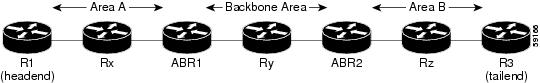
To configure an interarea tunnel, you specify on the headend router a loosely routed explicit path for the tunnel label-switched path (LSP) that identifies each ABR the LSP should traverse using the next-address loose command. The headend router and the ABRs along the specified explicit path expand the loose hops, each computing the path segment to the next ABR or tunnel destination.
For example, to configure a TE tunnel from router R1 to router R2 in the simple multiarea network shown in Figure 1, you would specify ABR1 and ABR2 as loose hops in the explicit path for the tunnel. To signal the tunnel LSP, the headend router (R1) computes the path to ABR1 and sends a Resource Reservation Protocol (RSVP) Path message specifying the path from itself to ABR1 as a sequence of strict hops followed by the path from ABR1 to the tailend as a sequence of loose hops (ABR2, R1). When ABR1 receives the Path message, it expands the path across the backbone area to ABR2 and forwards the Path message specifying the path from itself to ABR2 as a sequence of strict hops followed by the path from ABR2 to the tunnel tailend (R3) as a loose hop. When ABR2 receives the Path message, it expands the path across the tailend area to R3 and propagates the Path message specifying the path from itself to R2 as a sequence of strict hops.
Figure 1 Multiarea Network
Note
Note
Note
Note
The following MPLS TE features are supported on interarea traffic engineering LSPs:
•
•
•
•
•
Interarea Tunnels Benefits
When it is desirable for the traffic from one router to another router in a different IGP area to travel over TE LSPs, the MPLS Traffic Engineering: Interarea Tunnels feature allows you to configure a tunnel that runs from the source router to the destination router. The alternative would be to configure a sequence of tunnels, each crossing one of the areas between source and destination routers such that the traffic arriving on one such tunnel is forwarded into the next such tunnel.
How to Configure MPLS Traffic Engineering: Interarea Tunnels
This section contains the following tasks:
•
•
•
•
Note
Configuring OSPF for Interarea Tunnels
This section describes the following tasks:
•
•
Configuring OSPF for ABR Routers
For each ABR that is running OSPF, perform the following steps to configure traffic engineering on each area you want tunnels in or across. By having multiple areas and configuring traffic engineering in and across each area, changes within the network can be contained within an area.
SUMMARY STEPS
1.
2.
3.
4.
5.
6.
7.
8.
DETAILED STEPS
Configuring OSPF for Non-ABR Routers
For each non-ABR that is running OSPF, perform the following steps.
SUMMARY STEPS
1.
2.
3.
4.
5.
6.
7.
DETAILED STEPS
Configuring IS-IS for Interarea Tunnels
This section describes the following tasks:
•
•
•
Configuring IS-IS for Backbone Routers
To configure IS-IS for background (level-1-2) routers, perform the following steps.
SUMMARY STEPS
1.
2.
3.
4.
5.
6.
7.
8.
9.
10.
11.
12.
DETAILED STEPS
Configuring IS-IS for Nonbackbone Routers
To configure IS-IS for nonbackbone routers, perform the following steps.
SUMMARY STEPS
1.
2.
3.
4.
5.
6.
7.
8.
9.
DETAILED STEPS
Configuring IS-IS for Interfaces
To configure IS-IS for interfaces, perform the following steps.
SUMMARY STEPS
1.
2.
3.
4.
5.
6.
7.
8.
9.
10.
DETAILED STEPS
Configuring an MPLS Traffic Engineering Interarea Tunnel
This section includes the following tasks:
•
Configuring an MPLS Traffic Engineering Interarea Tunnel to Use Explicit Paths
To configure an MPLS traffic engineering interarea tunnel to use explicit paths, perform the following steps.
SUMMARY STEPS
1.
2.
3.
4.
5.
6.
7.
8.
9.
DETAILED STEPS
Configuring Explicit Paths
To configure explicit paths, perform the following steps.
SUMMARY STEPS
1.
2.
3.
4.
5.
DETAILED STEPS
Verifying the MPLS Traffic Engineering: Interarea Tunnels Configuration
To verify that the MPLS TE topology database maintained by the ABR includes the topologies of each area to which it is connected for which MPLS TE is enabled, perform the following steps. Enter the show mpls traffic-eng topology command at each ABR in the network.
SUMMARY STEPS
1.
2.
DETAILED STEPS
Configuration Examples for MPLS Traffic Engineering: Interarea Tunnels
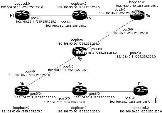
This section shows how to configure MPLS traffic engineering interarea tunnels for the simple router topology illustrated in Figure 2. It includes configuration fragments that illustrate the configurations shown in the following sections:
•
•
•
•
Note
Figure 2 Router Topology
Configuring OSPF for Interarea Tunnels: Example
The following configuration fragments show how to configure OSPF for interarea tunnels assuming that:
•
•
•
•
•
Router R1 OSPF Configuration
router ospf 1network 192.168.10.10 255.255.255.0 area 1network 192.168.35.0 0.0.255.255 area 1mpls traffic-eng router-id Loopback0mpls traffic-eng area 1Router Rx OSPF Configuration
router ospf 1network 192.168.30.30 area 1network 192.168.35.0 0.0.255.255 area 1network 192.168.45.0 0.0.255.255 area 1mpls traffic-eng router-id Loopback0mpls traffic-eng area 1Router Ra OSPF Configuration
Ra is an ABR for Area 0 and Area 1. Interface POS2/0 is in Area 1 and interface POS3/0 is in Area 0. The mpls traffic-eng area commands configure Ra for IGP TE updates for both areas.
router ospf 1network 192.168.40.40 area 0network 192.168.45.0 0.0.255.255 area 1network 192.168.55.0 0.0.255.255 area 0mpls traffic-eng router-id Loopback0mpls traffic-eng area 0mpls traffic-eng area 1Router Rb OSPF Configuration
Rb is an ABR for Area 0 and Area 2. Interface POS4/0 is in Area 0 and interface POS5/0 is in Area 2. The mpls traffic-eng area commands configure Rb for IGP TE updates for both areas.
router ospf 1network 192.168.60.60 0.0.0.0 area 0network 192.168.65.0 0.0.255.255 area 0network 192.168.75.0 0.0.255.255 area 2mpls traffic-eng router-id Loopback0mpls traffic-eng area 0mpls traffic-eng area 2Router Rz OSPF Configuration
router ospf 1network 192.168.70.70 0.0.0.0 area 2network 192.168.75.0 0.0.255.255 area 2network 192.168.85.0 0.0.255.255 area 2mpls traffic-eng router-id Loopback0mpls traffic-eng area 2Router R2 OSPF Configuration
router ospf 1network 192.168.20.20 0.0.0.0 area 2network 192.168.85.0 0.0.255.255 area 2mpls traffic-eng router-id Loopback0mpls traffic-eng area 2Configuring IS-IS for Interarea Tunnels: Example
The following configuration fragments illustrate how to configure IS-IS for interarea tunnels assuming that:
•
•
•
Router R1 IS-IS Configuration
clns routinginterface POS1/0ip router isisrouter isismetric-style widenet 49.0000.0100.0000.0010mpls traffic-eng router-id Loopback0mpls traffic-eng level-1Router Rx IS-IS Configuration
clns routinginterface POS1/0ip router isisinterface POS2/0ip router isisrouter isismetric-style widenet 49.0000.2000.0100.0001mpls traffic-eng router-id Loopback0mpls traffic-eng level-1Router Ra IS-IS Configuration
clns routinginterface POS2/0ip router isisinterface POS3/0ip router isisrouter isismetric-style widenet 49.0000.2000.0200.0002mpls traffic-eng router-id Loopback0mpls traffic-eng level-1mpls traffic-eng level-2Router Ry IS-IS Configuration
clns routinginterface POS3/0ip router isisinterface POS4/0ip router isisrouter isismetric-style widenet 49.0000.2000.0300.0003mpls traffic-eng router-id Loopback0mpls traffic-eng level-1mpls traffic-eng level-2Router Rb IS-IS Configuration
clns routinginterface POS4/0ip router isisinterface POS5/0ip router isisrouter isismetric-style widenet 49.0000.2000.0400.0004mpls traffic-eng router-id Loopback0mpls traffic-eng level-1mpls traffic-eng level-2Router Rz IS-IS Configuration
clns routinginterface POS5/0ip router isisinterface POS6/0ip router isisrouter isismetric-style widenet 49.0000.2000.0500.0005mpls traffic-eng router-id Loopback0mpls traffic-eng level-1Router R2 IS-IS Configuration
clns routinginterface POS6/0ip router isisrouter isismetric-style widenet 49.0000.0200.0000.0020mpls traffic-eng router-id Loopback0mpls traffic-eng level-1Configuring MPLS and RSVP to Support Traffic Engineering: Example
The following configuration fragments show how to configure MPLS and RSVP to support traffic engineering on the routers.
Router R1 Traffic Engineering Configuration
ip cefmpls traffic-eng tunnelsinterface Loopback0ip address 192.168.10.10 255.255.255.255interface POS1/0 !Each interface supporting MPLS TE must include the following:mpls traffic-eng tunnelsip rsvp bandwidth 1158The configuration of routers Rx, Ra, Ry, Rb, Rz, and R2 for traffic engineering operation is similar to that for R1.Configuring an Interarea Tunnel: Example
The following configuration fragments show how to configure a traffic engineering interarea tunnel. Router R1 is the headend for Tunnel1, and Router R2 is the tailend. Tunnel1 is configured with a path option that is loosely routed through Ra and Rb.
R1 Interarea Tunnel Configuration
The following commands configure an MPLS TE tunnel to use explicit paths:
interface Tunnel1ip unnumbered Loopback0tunnel destination 192.168.20.20tunnel mode mpls traffic-engtunnel mpls traffic-eng bandwidth 300tunnel mpls traffic-eng path-option 1 explicit name path-tunnel1The following commands configure an explicit path:
ip explicit-path name path-tunnel1next-address loose 192.168.40.40next-address loose 192.168.60.60next-address loose 192.168.20.20 !Specifying the tunnel tailend in the loosely routed!path is optional.
Note
Additional References
The following sections provide references related to the MPLS Traffic Engineering: Interarea Tunnels feature.
Related Documents
IS-IS
•
•
Link protection
MPLS Traffic Engineering Fast Reroute—Link Protection, Release 12.0(16)ST
MPLS traffic engineering
•
•
•
OSPF
•
•
Standards
No new or modified standards are supported by this feature, and support for existing standards has not been modified by this feature.
—
MIBs
RFCs
Technical Assistance
Command Reference
This section documents only commands that are new or modified.
next-address
To specify the next IP address in the explicit path, use the next-address command in IP explicit path configuration mode. To remove the specified next IP address in the explicit path, use the no form of this command.
next-address [loose | strict] A.B.C.D
no next-address A.B.C.D
Syntax Description
Defaults
The next IP address in the explicit path is not specified.
Command Modes
IP explicit path configuration
Command History
Usage Guidelines
To specify an explicit path that includes only the addresses specified, specify each address in sequence by using the next-address command without the loose keyword.
To configure an interarea traffic engineering (TE) tunnel, configure the tunnel path options as loose explicit paths. Specify that each autonomous system border router (ASBR) traversed by the tunnel LSP is a loose hop by entering the loose keyword with the next-address command.
To use explicit paths for TE tunnels within an IGP area, you can specify a combination of both loose and strict hops.
Examples
The following example shows how to assign the number 60 to the IP explicit path, enable the path, and specify 10.3.27.3 as the next IP address in the list of IP addresses:
Router(config)# ip explicit-path identifier 60 enableRouter(cfg-ip-expl-path)# next-address 10.3.27.3Explicit Path identifier 60:1: next-address 10.3.27.3The following example shows a loose IP explicit path with ID 60. An interarea TE tunnel has a destination of 10.3.29.3 and traverses ASBRs 10.3.27.3 and 10.3.28.3.
Router(config)# ip explicit-path identifier 60Router(cfg-ip-expl-path)# next-address loose 10.3.27.3Router(cfg-ip-expl-path)# next-address loose 10.3.28.3Router(cfg-ip-expl-path)# next-address loose 10.3.29.3Related Commands
Feature History for MPLS Traffic Engineering: Interarea Tunnels
Table 1 lists the release history for this feature.
Not all commands may be available in your Cisco IOS software release. For release information about a specific command, see the command reference documentation.
Cisco IOS software images are specific to a Cisco IOS software release, a feature set, and a platform. Use Cisco Feature Navigator to find information about platform support and Cisco IOS software image support. Access Cisco Feature Navigator at http://www.cisco.com/go/cfn. You must have an account on Cisco.com. If you do not have an account or have forgotten your username or password, click Cancel at the login dialog box and follow the instructions that appear.
Note
Glossary
ABR—Area Border Router. A router connecting two areas. In OSPF, ABRs belong to both areas and must maintain separate topological databases for each. When an OSPF router has interfaces in more than one area, it is an Area Border Router.
area—A logical set of network segments (for example, one that is OSPF-based) and their attached devices. Areas usually are connected to other areas by routers, making up a single autonomous system. OSPF and IS-IS define their areas differently. OSPF area borders are marked by routers. Some interfaces are in one area, and other interfaces are in another area. With IS-IS, all the routers are completely within an area, and the area borders are on links, not on routers. The routers that connect the areas are level-2 routers, and routers that have no direct connectivity to another area are level-1 routers.
area ID—In an IS-IS router, this area address is associated with the entire router rather than an interface. A router can have up to three area addresses. Both the area ID and the system ID are defined on an IS-IS router by a single address, the Network Entry Title (NET).
autonomous system—A collection of networks under a common administration sharing a common routing strategy. Autonomous systems are subdivided by areas.
Cisco Express Forwarding—An advanced Layer 3 IP switching technology. Cisco Express Forwarding optimizes network performance and scalability for networks that have large and dynamic traffic patterns, such as the Internet, and for networks characterized by intensive Web-based applications or interactive sessions. Cisco Express Forwarding uses a Forwarding Information Base (FIB) to make IP destination prefix-based switching decisions. The FIB is conceptually similar to a routing table or information base. When routing or topology changes occur in the network, the IP routing table is updated, and those changes are reflected in the FIB. The FIB maintains next-hop address information based on the information in the IP routing table.
headend—The upstream, transmit end of a tunnel. The router that originates and maintains the traffic engineering LSP.
IGP—Interior Gateway Protocol. Internet protocol used to exchange routing information within an autonomous system. Examples of common IGPs include OSPF and Routing Information Protocol (RIP).
interarea TE—Ability for a traffic engineering LSP to span multiple areas.
IS-IS—Intermediate System-to-Intermediate System. IS-IS is an OSI link-state hierarchial routing protocol based on DECnet Phase V routing, where intermediate system (IS) routers exchange routing information is based on a single metric to determine the network topology.
label-switched path (LSP) tunnel—A configured connection between two routers in which label switching is used to carry the packets.
level-1 routers—Routers that are directly connected to other areas. The routers are not in the backbone. MPLS does not run in the background. These routers are also called internal routers.
level-2 routers—Routers that connect two areas. These routers let you run MPLS in the background.
load balancing—The distribution of traffic among multiple paths to the same destination so that the router uses bandwidth efficiently. Load balancing increases the use of network segments, thus increasing effective network bandwidth.
LSP—label-switched path. A sequence of hops (such as R0...Rn) in which a packet travels from R0 to Rn through label switching mechanisms. A label-switched path can be chosen dynamically, based on normal routing mechanisms, or through configuration.
mask—A bit combination used to describe which part of an address refers to the network or the subnet and which part refers to the host.
MPLS—Multiprotocol Label Switching. A method for forwarding packets (frames) through a network. It enables routers at the edge of a network to apply labels to packets. ATM switches or existing routers in the network core can switch packets according to the labels with minimal lookup overhead.
OSPF—Open Shortest Path First. Link-state, hierarchical IGP routing algorithm proposed as a successor to Routing Information Protocol (RIP) in the Internet community. OSPF features include least-cost routing, multipath routing, and load balancing.
process ID—Distinguishes one process from another within the device. An OSPF process ID can be any positive integer, and it has no significance outside the router on which it is configured.
router ID—Something by which a router originating a packet can be uniquely distinguished from all other routers. For example, an IP address from one of the router's interfaces.
tailend—The downstream, receive end of a tunnel. The router that terminates the traffic engineering LSP.
traffic engineering—The techniques and processes that cause routed traffic to travel through the network on a path other than the one that would have been chosen if standard routing methods were used.
tunnel—A secure communication path between two peers, such as two routers. A traffic engineering tunnel is a label-switched tunnel that is used for traffic engineering. Such a tunnel is set up through means other than normal Layer 3 routing; it is used to direct traffic over a path different from the one that Layer 3 routing could cause the tunnel to take.
virtual link—Ordinarily, each area is directly connected to area 0. A virtual link is used for a connection when an area is connected to an area that is one area away from area 0.
Note
Any Internet Protocol (IP) addresses used in this document are not intended to be actual addresses. Any examples, command display output, and figures included in the document are shown for illustrative purposes only. Any use of actual IP addresses in illustrative content is unintentional and coincidental.
© 2003-2007 Cisco Systems, Inc. All rights reserved.