Feedback Feedback
|
Table Of Contents
Frame Relay Queueing and Fragmentation
at the InterfaceHow Frame Relay Queueing and Fragmentation at the Interface Works
Supported Standards, MIBs, and RFCs
Configuring Class Policy for the Priority Queue
Configuring Class Policy for the Bandwidth Queues
Configuring the Shaping Policy Using the Class-Default Class
Configuring Queueing and Fragmentation on the Frame Relay Interface
Verifying Frame Relay Queueing and Fragmentation at the Interface
Monitoring and Maintaining Frame Relay Queueing and Fragmentation at the Interface
Frame Relay Queueing, Shaping, and Fragmentation at the Interface Example
Frame Relay Queueing and Fragmentation at the Interface Example
frame-relay fragment end-to-end
Frame Relay Queueing and Fragmentation
at the Interface
Feature History
This document describes the Frame Relay Queueing and Fragmentation at the Interface feature in Cisco IOS Release 12.2(14)S and includes the following sections:
•
Supported Standards, MIBs, and RFCs
•
Feature Overview
The Frame Relay Queueing and Fragmentation at the Interface feature introduces support for low-latency queueing (LLQ) and FRF.12 end-to-end fragmentation on a Frame Relay interface. This new feature simplifies the configuration of low-latency, low-jitter quality of service (QoS) by enabling the queueing policy and fragmentation configured on the main interface to apply to all permanent virtual circuits (PVCs) and subinterfaces under that interface. Before the introduction of this feature, queueing and fragmentation had to be configured on each individual PVC. Subrate shaping can also be configured on the interface.
How Frame Relay Queueing and Fragmentation at the Interface Works
When FRF.12 end-to-end fragmentation is enabled on an interface, all PVCs on the main interface and its subinterfaces will have fragmentation enabled with the same configured fragment size. To maintain low latency and low jitter for higher priority traffic, the configured fragment size must be greater than the largest high-priority frames. This configuration will prevent priority traffic from being fragmented and queued behind non-priority fragmented frames. If the size of a priority frame is larger than the configured fragment size, the priority frame will be fragmented. Local Management Interface (LMI) traffic will not be fragmented and is guaranteed its required bandwidth.
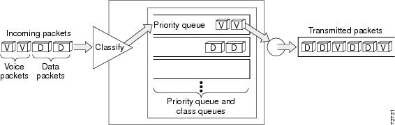
When a low-latency queueing policy map is applied to the interface, traffic through the interface is identified using class maps and is directed to the appropriate queue. Time-sensitive traffic such as voice should be classified as high priority and will be queued on the priority queue. Traffic that does not fall into one of the defined classes will be queued on the class-default queue. Frames from the priority queue and class queues are subject to fragmentation and interleaving. As long as the configured fragment size is larger than the high-priority frames, the priority queue traffic will not be fragmented and will be interleaved with fragmented frames from other class queues. This approach provides the highest QoS transmission for priority queue traffic. Figure 1 illustrates the interface queueing and fragmentation process.
Figure 1 Frame Relay Queueing and Fragmentation at the Interface
Subrate shaping can also be applied to the interface, but interleaving of priority frames will not work when shaping is configured. If shaping is not configured, each PVC will be allowed to send bursts of traffic up to the physical line rate.
When shaping is configured and traffic exceeds the rate at which the shaper can send frames, the traffic is queued at the shaping layer using fair queueing. After a frame passes through the shaper, the frame is queued at the interface using whatever queueing method is configured. If shaping is not configured, then queueing occurs only at the interface.
Note
The Frame Relay Queueing and Fragmentation at the Interface feature supports the following functionality:
•
•
•
•
Benefits
Simple Configuration
The Frame Relay Queueing and Fragmentation at the Interface feature allows fragmentation, low latency queueing, and subrate shaping to be configured on a Frame Relay interface queue. The fragmentation and queueing and shaping policy will apply to all PVCs and subinterfaces under the main interface, eliminating the need to configure QoS on each PVC individually.
Flexible Bandwidth
This feature allows PVCs to preserve the logical separation of traffic from different services while reducing bandwidth partitioning between PVCs. Each PVC can send bursts of traffic up to the interface shaping rate or, if shaping is not configured, the physical interface line rate.
Restrictions
•
•
•
•
Related Documents
For more information about shaping and low-latency queueing for Frame Relay, refer to the following documents:
•
•
•
For more information about Frame Relay fragmentation, refer to the following documents:
•
•
Supported Platforms
•
•
•
Determining Platform Support Through Cisco Feature Navigator
Cisco IOS software is packaged in feature sets that support specific platforms. To get updated information regarding platform support for this feature, access Cisco Feature Navigator. Cisco Feature Navigator dynamically updates the list of supported platforms as new platform support is added for the feature.
Cisco Feature Navigator is a web-based tool that enables you to determine which Cisco IOS software images support a specific set of features and which features are supported in a specific Cisco IOS image. You can search by feature or release. Under the release section, you can compare releases side by side to display both the features unique to each software release and the features in common.
To access Cisco Feature Navigator, you must have an account on Cisco.com. If you have forgotten or lost your account information, send a blank e-mail to cco-locksmith@cisco.com. An automatic check will verify that your e-mail address is registered with Cisco.com. If the check is successful, account details with a new random password will be e-mailed to you. Qualified users can establish an account on Cisco.com by following the directions at http://www.cisco.com/register.
Cisco Feature Navigator is updated regularly when major Cisco IOS software releases and technology releases occur. For the most current information, go to the Cisco Feature Navigator home page at the following URL:
Availability of Cisco IOS Software Images
Platform support for particular Cisco IOS software releases is dependent on the availability of the software images for those platforms. Software images for some platforms may be deferred, delayed, or changed without prior notice. For updated information about platform support and availability of software images for each Cisco IOS software release, refer to the online release notes or, if supported, Cisco Feature Navigator.
Supported Standards, MIBs, and RFCs
Standards
FRF.12, Frame Relay Fragmentation Implementation Agreement, December 1997
MIBs
No new or modified MIBs are supported by this feature.
To obtain lists of supported MIBs by platform and Cisco IOS release, and to download MIB modules, go to the Cisco MIB website on Cisco.com at the following URL:
http://www.cisco.com/public/sw-center/netmgmt/cmtk/mibs.shtml
RFCs
No new or modified RFCs are supported by this feature.
Prerequisites
The tasks in this document assume that you know how to configure low-latency queueing and shaping service policies.
The following prerequisites are specific to the Cisco 7500 series:
•
•
Configuration Tasks
See the following sections for configuration tasks for the Frame Relay Queueing and Fragmentation at the Interface feature. Each task in the list is identified as either required or optional.
•
•
•
•
•
Configuring Class Policy for the Priority Queue
To configure a policy map for the priority class, use the following commands beginning in global configuration mode.
Configuring Class Policy for the Bandwidth Queues
To configure a policy map and create class policies that make up the service policy, use the following commands beginning in global configuration mode:
Configuring the Shaping Policy Using the Class-Default Class
In general, the class-default class is used to classify traffic that does not fall into one of the defined classes. Even though the class-default class is predefined when you create the policy map, you still have to configure it. If a default class is not configured, traffic that does not match any of the configured classes is given best-effort treatment, which means that the network will deliver the traffic if it can, without any assurance of reliability, delay prevention, or throughput.
If you configure shaping in addition to queueing on the interface, use the class-default class to configure the shaping policy. The shaping policy will serve as the parent in a hierarchical traffic policy. The queueing policy will serve as the child policy. The class-default class is used for the shaping policy so that all traffic for the entire interface is shaped and a bandwidth-limited stream can be created.
To configure the shaping policy in the class-default class, use the following commands beginning in global configuration mode:
Configuring Queueing and Fragmentation on the Frame Relay Interface
To configure low-latency queueing and FRF.12 end-to-end fragmentation on a Frame Relay interface, use the following commands beginning in global configuration mode:
Verifying Frame Relay Queueing and Fragmentation at the Interface
To verify the configuration and performance of Frame Relay queueing and fragmentation at the interface, perform the following steps:
Step 1
Router# show running-configBuilding configuration......class-map match-all voicematch ip precedence 5!!policy-map llqclass voicepriority 64policy-map shaperclass class-defaultshape peak 96000service-policy llq!!interface Serial1/1ip address 16.0.0.1 255.255.255.0encapsulation frame-relayservice-policy output shaperframe-relay fragment 80 end-to-end!Step 2
The following sample output for the show policy-map interface command is based on the configuration in Step 1:
Router# show policy-map interface serial 1/1Serial1/1Service-policy output:shaperClass-map:class-default (match-any)12617 packets, 1321846 bytes5 minute offered rate 33000 bps, drop rate 0 bpsMatch:anyTraffic ShapingTarget/Average Byte Sustain Excess Interval IncrementRate Limit bits/int bits/int (ms) (bytes)192000/96000 1992 7968 7968 83 1992Adapt Queue Packets Bytes Packets Bytes ShapingActive Depth Delayed Delayed Active- 0 12586 1321540 0 0 noService-policy :llqClass-map:voice (match-all)3146 packets, 283140 bytes5 minute offered rate 7000 bps, drop rate 0 bpsMatch:ip precedence 1Weighted Fair QueueingStrict PriorityOutput Queue:Conversation 24Bandwidth 64 (kbps) Burst 1600 (Bytes)(pkts matched/bytes matched) 0/0(total drops/bytes drops) 0/0Class-map:class-default (match-any)9471 packets, 1038706 bytes5 minute offered rate 26000 bpsMatch:anyStep 3
The following sample output for the show interfaces serial command is based on the configuration in Step 1:
Router# show interfaces serial 1/1Serial1/1 is up, line protocol is upHardware is M4TInternet address is 10.0.0.1/24MTU 1500 bytes, BW 1544 Kbit, DLY 20000 usec,reliability 255/255, txload 5/255, rxload 1/255Encapsulation FRAME-RELAY, crc 16, loopback not setKeepalive set (10 sec)Restart-Delay is 0 secsLMI enq sent 40, LMI stat recvd 40, LMI upd recvd 0, DTE LMI upLMI enq recvd 0, LMI stat sent 0, LMI upd sent 0LMI DLCI 1023 LMI type is CISCO frame relay DTEFragmentation type:end-to-end, size 80, PQ interleaves 0Broadcast queue 0/64, broadcasts sent/dropped 0/0, interface broadcasts 0Last input 00:00:03, output 00:00:00, output hang neverLast clearing of "show interface" counters 00:06:34Input queue:0/75/0/0 (size/max/drops/flushes); Total output drops:0Queueing strategy:weighted fairOutput queue:0/1000/64/0 (size/max total/threshold/drops)Conversations 0/1/256 (active/max active/max total)Reserved Conversations 0/0 (allocated/max allocated)Available Bandwidth 1158 kilobits/sec5 minute input rate 0 bits/sec, 0 packets/sec5 minute output rate 33000 bits/sec, 40 packets/sec40 packets input, 576 bytes, 0 no bufferReceived 0 broadcasts, 0 runts, 0 giants, 0 throttles0 input errors, 0 CRC, 0 frame, 0 overrun, 0 ignored, 0 abort15929 packets output, 1668870 bytes, 0 underruns0 output errors, 0 collisions, 0 interface resets0 output buffer failures, 0 output buffers swapped out0 carrier transitions DCD=up DSR=up DTR=up RTS=up CTS=up
Monitoring and Maintaining Frame Relay Queueing and Fragmentation at the Interface
To monitor and maintain Frame Relay queueing and fragmentation at the interface, use the following commands in privileged EXEC mode:
Configuration Examples
This section provides the following configuration example:
•
•
Frame Relay Queueing, Shaping, and Fragmentation at the Interface Example
The following example shows the configuration of a hierarchical policy for low-latency queueing, FRF.12 fragmentation, and shaping on serial interface 3/2. Note that traffic from the priority queue will not be interleaved with fragments from the class-default queue because shaping is configured.
class-map voicematch access-group 101policy-map llqclass voicepriority 64policy-map shaperclass class-defaultshape average 96000service-policy llqinterface serial 3/2ip address 10.0.0.1 255.0.0.0encapsulation frame-relaybandwidth 128clock rate 128000service-policy output shaperframe-relay fragment 80 end-to-endaccess-list 101 match ip any host 10.0.0.2Frame Relay Queueing and Fragmentation at the Interface Example
The following example shows the configuration of low-latency queueing and FRF.12 fragmentation on serial interface 3/2. Because shaping is not being used, a hierarchical traffic policy is not needed and traffic from the priority queue will be interleaved with fragments from the other queues. Without shaping, the output rate of the interface is equal to the line rate or configured clock rate. In this example, the clock rate is 128,000 bps.
class-map voicematch access-group 101policy-map llqclass voicepriority 64class videobandwidth 32interface serial 3/2ip address 10.0.0.1 255.0.0.0encapsulation frame-relaybandwidth 128clock rate 128000service-policy output llqframe-relay fragment 80 end-to-endaccess-list 101 match ip any host 10.0.0.2Command Reference
This section documents modified commands. All other commands used with this feature are documented in the Cisco IOS Release 12.2 command reference publications.
•
frame-relay fragment end-to-end
To enable fragmentation of Frame Relay frames on an interface, use the frame-relay fragment end-to-end command in interface configuration mode. To disable Frame Relay fragmentation, use the no form of this command.
frame-relay fragment fragment-size end-to-end
no frame-relay fragment
Syntax Description
Defaults
Disabled
Command Modes
Interface configuration
Command History
12.2(14)S
This command was introduced to enable fragmentation on a Frame Relay interface.
Usage Guidelines
Interface fragmentation and class-based fragmentation cannot be configured at the same time. To configure class-based fragmentation that can be applied to individual permanent virtual circuits (PVCs), use the frame-relay fragment command in map-class configuration mode.
Interface fragmentation supports the following types of fragment formats:
•
•
•
When fragmentation is enabled on an interface, all PVCs on the main interface and its subinterfaces will have fragmentation enabled with the same configured fragment size.
When configuring fragmentation on an interface with low- latency queueing, configure the fragment size to be greater than the largest high-priority frame that would be expected. This configuration will prevent higher priority traffic from being fragmented and queued up behind lower priority fragmented frames. If the size of a priority frame is larger than the configured fragment size, the priority frame will be fragmented.
Local Management Interface (LMI) traffic will not be fragmented.
Note the following interface fragmentation restrictions:
•
•
Examples
The following example shows the configuration of low-latency queueing, FRF.12 fragmentation, and shaping on serial interface 3/2. Note that traffic from the priority queue will not be interleaved with fragments from the class-default queue because shaping is configured.
class-map voicematch access-group 101policy-map llqclass voicepriority 64policy-map shaperclass class-defaultshape average 96000service-policy llqinterface serial 3/2ip address 10.0.0.1 255.0.0.0encapsulation frame-relaybandwidth 128clock rate 128000service-policy output shaperframe-relay fragment 80 end-to-endaccess-list 101 match ip any host 10.0.0.2Related Commands
show interfaces serial
To display information about a serial interface, use the show interfaces serial command in privileged EXEC mode. When using Frame Relay encapsulation, use the show interfaces serial command in user EXEC or privileged EXEC mode to display information about the multicast data-link connection identifier (DLCI), the DLCIs used on the interface, and the DLCI used for the Local Management Interface (LMI).
Cisco 4000 Series
show interfaces serial [number[:channel-group]] [accounting]
Cisco 7200 Series
show interfaces serial [slot/port] [accounting]
Cisco 7000 and Cisco 7500 Series with the RSP7000, RSP7000CI, or Ports on VIPs
show interfaces serial [slot/port-adapter/port]
Cisco 7500 Series
show interfaces serial [slot/port[:channel-group]] [accounting]
Cisco 7500 Series with a CT3IP
show interfaces serial [slot/port-adapter/port][:t1-channel] [accounting | crb]
Cisco AS5350 and Cisco AS5400 Universal Gateways
show interfaces serial slot/port
Cisco AS5800 Access Servers
show interfaces serial dial-shelf/slot/t3-port:t1-num:chan-group
Syntax Description
Command Modes
User EXEC (when Frame Relay encapsulation is used)
Privileged EXECCommand History
Usage Guidelines
Frame Relay
Use this command to determine the status of the Frame Relay link. This display also indicates Layer 2 status if switched virtual circuits (SVCs) are configured.
Channel Groups as Virtual Serial Interfaces
To find out about channel groups configured as virtual serial interfaces, to verify that the router has High-Level Data Link Control (HDLC) encapsulation on the interface, and to verify that the interface sees the loopback, use the show interfaces serial command in privileged EXEC mode.
Examples
Example of Synchronous Serial Interface
The following is sample output from the show interfaces serial command for a synchronous serial interface:
Router# show interfaces serialSerial 0 is up, line protocol is upHardware is MCI SerialInternet address is 192.168.10.203, subnet mask is 255.255.255.0MTU 1500 bytes, BW 1544 Kbit, DLY 20000 usec, rely 255/255, load 1/255Encapsulation HDLC, loopback not set, keepalive set (10 sec)Last input 0:00:07, output 0:00:00, output hang neverOutput queue 0/40, 0 drops; input queue 0/75, 0 dropsFive minute input rate 0 bits/sec, 0 packets/secFive minute output rate 0 bits/sec, 0 packets/sec16263 packets input, 1347238 bytes, 0 no bufferReceived 13983 broadcasts, 0 runts, 0 giants2 input errors, 0 CRC, 0 frame, 0 overrun, 0 ignored, 2 abort1 carrier transitions22146 packets output, 2383680 bytes, 0 underruns0 output errors, 0 collisions, 2 interface resets, 0 restartsTable 1 describes significant fields shown in the display.
Example of PA-2JT2 Serial Interface
The following is sample output from the show interfaces serial command for a PA-2JT2 serial interface:
Router# show interfaces serial 3/0/0Serial3/0/0 is up, line protocol is upHardware is cyBus SerialInternet address is 10.0.0.1/8MTU 1500 bytes, BW 6312 Kbit, DLY 20000 usec, rely 255/255, load 26/255Encapsulation HDLC, loopback not set, keepalive not setLast input 00:04:31, output 00:04:31, output hang neverLast clearing of "show interface" counters 00:06:07Queueing strategy: fifoOutput queue 0/40, 0 drops; input queue 0/75, 0 drops5 minute input rate 162000 bits/sec, 8 packets/sec5 minute output rate 162000 bits/sec, 8 packets/sec20005 packets input, 20080520 bytes, 0 no bufferReceived 0 broadcasts, 0 runts, 0 giants0 input errors, 0 CRC, 0 frame, 0 overrun, 0 ignored, 0 abort20005 packets output, 20080520 bytes, 0 underruns0 output errors, 0 collisions, 0 interface resets0 output buffer failures, 0 output buffers swapped out0 carrier transitions0 cv errors, 0 crc5 errors, 0 frame errorsrxLOS inactive, rxLOF inactive, rxPAIS inactiverxAIS inactive, rxRAI inactive, rxHBER inactiveTable 2 describes significant fields shown in the display that are different from the fields described in Table 1.
Example of PA-E3 Serial Port Adapter
The following is sample output from the show interfaces serial command for a PA-E3 serial port adapter installed in chassis slot 2:
Router# show interfaces serial 2/0Serial2/0 is up, line protocol is upHardware is M1T-E3 paInternet address is 172.17.1.1/24MTU 4470 bytes, BW 34010 Kbit, DLY 200 usec, rely 128/255, load 1/255Encapsulation HDLC, loopback not set, keepalive not setLast input 1w0d, output 00:00:48, output hang neverLast clearing of "show interface" counters 1w0dQueueing strategy: fifoOutput queue 0/40, 0 drops; input queue 0/75, 0 drops5 minute input rate 0 bits/sec, 0 packets/sec5 minute output rate 0 bits/sec, 0 packets/sec20 packets input, 2080 bytes, 0 no bufferReceived 0 broadcasts, 0 runts, 0 giants, 0 parity0 input errors, 0 CRC, 0 frame, 0 overrun, 0 ignored, 0 abort11472 packets output, 3824748 bytes, 0 underruns0 output errors, 0 applique, 0 interface resets0 output buffer failures, 0 output buffers swapped out0 carrier transitionsrxLOS inactive, rxLOF inactive, rxAIS inactivetxAIS inactive, rxRAI inactive, txRAI inactiveTable 3 describes significant fields shown in the display that are different from the fields described in Table 1.
Example of 1-Port PA-T3 Serial Port Adapter Installed in a VIP2
The following is sample output from the show interfaces serial command for a 1-port PA-T3 serial port adapter installed in a VIP2 in chassis slot 1, in port adapter slot 0:
Router# show interfaces serial 1/0/0Serial1/0/0 is up, line protocol is upHardware is cyBus PODS3 SerialInternet address is 172.18.1.1/24MTU 4470 bytes, BW 44736 Kbit, DLY 200 usec, rely 255/255, load 1/255Encapsulation HDLC, loopback not set, keepalive set (10 sec)Last input 00:00:05, output 00:00:02, output hang neverLast clearing of "show interface" counters 5d02hQueueing strategy: fifoOutput queue 0/40, 0 drops; input queue 0/75, 27269 drops5 minute input rate 0 bits/sec, 0 packets/sec5 minute output rate 0 bits/sec, 0 packets/sec79039 packets input, 14195344 bytes, 0 no bufferReceived 84506 broadcasts, 0 runts, 0 giants0 parity9574 input errors, 6714 CRC, 0 frame, 1 overrun, 0 ignored, 2859 abort62472 packets output, 13751644 bytes, 0 underruns0 output errors, 0 applique, 10 interface resets0 output buffer failures, 0 output buffers swapped out16 carrier transitionsrxLOS inactive, rxLOF inactive, rxAIS inactivetxAIS inactive, rxRAI inactive, txRAI inactiveTable 4 describes significant fields shown in the display that are different from the fields described in Table 1.
Example of CT3IP Serial Interface
The following is sample output from the show interfaces serial command for the CT3IP serial interface:
Router# show interfaces serial 3/0/0:25Serial3/0/0:25 is up, line protocol is upHardware is cyBus T3Internet address is 10.25.25.2/24MTU 1500 bytes, BW 1536 Kbit, DLY 20000 usec, rely 255/255, load 12/255Encapsulation HDLC, loopback not set, keepalive not setLast input 00:19:01, output 00:11:49, output hang neverLast clearing of "show interface" counters 00:19:39Input queue: 0/75/0 (size/max/drops); Total output drops: 0Queueing strategy: weighted fairOutput queue: 0/64/0 (size/threshold/drops)Conversations 0/1 (active/max active)Reserved Conversations 0/0 (allocated/max allocated)5 minute input rate 69000 bits/sec, 90 packets/sec5 minute output rate 71000 bits/sec, 90 packets/sec762350 packets input, 79284400 bytes, 0 no bufferReceived 0 broadcasts, 0 runts, 0 giants150 input errors, 0 CRC, 0 frame, 150 overrun, 0 ignored, 0 abort763213 packets output, 80900472 bytes, 0 underruns0 output errors, 0 collisions, 0 interface resets0 output buffer failures, 0 output buffers swapped out0 carrier transitions no alarm presentTimeslot(s) Used:1-24, Transmitter delay is 0 flags, transmit queue length 5non-inverted dataTable 5 describes significant fields relevant to the CT3IP shown in the display that are different from the fields described in Table 1.
Example of an HDLC Synchronous Serial Interface on a Cisco 7500 Series Router
The following is sample output from the show interfaces serial command for an HDLC synchronous serial interface on a Cisco 7500 series router:
Router# show interfaces serial 1/0Serial1/0 is up, line protocol is upHardware is cxBus SerialInternet address is 172.19.190.203, subnet mask is 255.255.255.0MTU 1500 bytes, BW 1544 Kbit, DLY 20000 usec, rely 255/255, load 1/255Encapsulation HDLC, loopback not set, keepalive set (10 sec)Last input 0:00:07, output 0:00:00, output hang neverLast clearing of "show interface" counters 2w4dOutput queue 0/40, 0 drops; input queue 0/75, 0 dropsFive minute input rate 0 bits/sec, 0 packets/secFive minute output rate 0 bits/sec, 0 packets/sec16263 packets input, 1347238 bytes, 0 no bufferReceived 13983 broadcasts, 0 runts, 0 giants2 input errors, 0 CRC, 0 frame, 0 overrun, 0 ignored, 2 abort22146 packets output, 2383680 bytes, 0 underruns0 output errors, 0 collisions, 2 interface resets, 0 restarts1 carrier transitionsTable 1 describes significant fields shown in the display.
Example of HDLC Encapsulation
The following example displays High-Level Data Link Control (HDLC) encapsulation on serial interface 0:
Router# show interfaces serial 0Serial0 is up, line protocol is up (looped)Hardware is HD64570Internet address is 10.1.1.1, subnet mask is 255.255.255.0MTU 1500 bytes, BW 1544 Kbit, DLY 20000 usec, rely 255/255, load 1/255Encapsulation HDLC, loopback set, keepalive set (10 sec)Table 1 describes significant fields shown in the display.
Example of a G.703 Interface with Framing
The following is sample output from the show interfaces serial command for a G.703 interface on which framing is enabled:
Router# show interfaces serial 2/3Serial2/3 is up, line protocol is upHardware is cxBus SerialInternet address is 10.4.4.1, subnet mask is 255.255.255.0MTU 1500 bytes, BW 1544 Kbit, DLY 20000 usec, rely 255/255, load 1/255Encapsulation HDLC, loopback not set, keepalive not setLast input 0:00:21, output 0:00:21, output hang neverLast clearing of "show interface" counters neverOutput queue 0/40, 0 drops; input queue 0/75, 0 dropsFive minute input rate 0 bits/sec, 0 packets/secFive minute output rate 0 bits/sec, 0 packets/sec53 packets input, 7810 bytes, 0 no bufferReceived 53 broadcasts, 0 runts, 0 giants2 input errors, 2 CRC, 0 frame, 0 overrun, 0 ignored, 2 abort56 packets output, 8218 bytes, 0 underruns0 output errors, 0 collisions, 2 interface resets, 0 restarts1 carrier transitions2 alarm indications, 333 remote alarms, 332 rx LOF, 0 rx LOSRTS up, CTS up, DTR up, DCD up, DSR upBER inactive, NELR inactive, FELR inactiveTable 1 describes significant fields shown in the display.
Example with Frame Relay Encapsulation
When using Frame Relay encapsulation, use the show interfaces serial command to display information on the multicast data-link connection identifier (DLCI), the DLCI of the interface, and the DLCI used for the local management interface (LMI).
The multicast DLCI and the local DLCI can be set using the frame-relay multicast-dlci and frame-relay local-dlci configuration commands. The status information is taken from the LMI, when active.
The following is sample output from the show interfaces serial command when Frame Relay encapsulation and LMI are enabled:
Router# show interfaces serialSerial 2 is up, line protocol is upHardware type is MCI SerialInternet address is 172.20.122.1, subnet mask is 255.255.255.0MTU 1500 bytes, BW 1544 Kbit, DLY 20000 usec, rely 255/255, load 1/255Encapsulation FRAME-RELAY, loopback not set, keepalive set (10 sec)multicast DLCI 1022, status defined, activesource DLCI 20, status defined, activeLMI DLCI 1023, LMI sent 10, LMI stat recvd 10, LMI upd recvd 2Last input 7:21:29, output 0:00:37, output hang neverOutput queue 0/100, 0 drops; input queue 0/75, 0 dropsFive minute input rate 0 bits/sec, 0 packets/secFive minute output rate 0 bits/sec, 0 packets/sec47 packets input, 2656 bytes, 0 no bufferReceived 5 broadcasts, 0 runts, 0 giants5 input errors, 0 CRC, 0 frame, 0 overrun, 0 ignored, 57 abort518 packets output, 391205 bytes0 output errors, 0 collisions, 0 interface resets, 0 restarts1 carrier transitionsIn this display, the multicast DLCI has been changed to 1022 using the frame-relay multicast-dlci interface configuration command.
The display shows the statistics for the LMI as the number of status inquiry messages sent (LMI sent), the number of status messages received (LMI recvd), and the number of status updates received (upd recvd). Refer to the Frame Relay Interface specification for additional explanations of this output.
Example with Frame Relay Queueing and Fragmentation at the Interface
The following is sample output from the show interfaces serial command when low-latency queueing and FRF.12 end-to-end fragmentation are configured on a Frame Relay interface:
Router# show interfaces serial 3/2Serial3/2 is up, line protocol is upHardware is M4TMTU 1500 bytes, BW 1544 Kbit, DLY 20000 usec,reliability 255/255, txload 1/255, rxload 1/255Encapsulation FRAME-RELAY, crc 16, loopback not setKeepalive set (10 sec)LMI enq sent 0, LMI stat recvd 0, LMI upd recvd 0, DTE LMI upLMI enq recvd 0, LMI stat sent 0, LMI upd sent 0LMI DLCI 1023 LMI type is CISCO frame relay DTEFragmentation type: end-to-end, size 80, PQ interleaves 0Broadcast queue 0/64, broadcasts sent/dropped 0/0, interface broadcasts 0Last input 2d15h, output 2d15h, output hang neverLast clearing of "show interface" counters 00:01:31Input queue: 0/75/0/0 (size/max/drops/flushes); Total output drops: 0Queueing strategy: weighted fairOutput queue: 0/1000/64/0 (size/max total/threshold/drops)Conversations 0/0/256 (active/max active/max total)Reserved Conversations 0/0 (allocated/max allocated)Available Bandwidth 1094 kilobits/sec5 minute input rate 0 bits/sec, 0 packets/sec5 minute output rate 0 bits/sec, 0 packets/sec0 packets input, 0 bytes, 0 no bufferReceived 0 broadcasts, 0 runts, 0 giants, 0 throttles0 input errors, 0 CRC, 0 frame, 0 overrun, 0 ignored, 0 abort0 packets output, 0 bytes, 0 underruns0 output errors, 0 collisions, 1 interface resets0 output buffer failures, 0 output buffers swapped out1 carrier transitions DCD=up DSR=up DTR=up RTS=up CTS=upTable 6 describes significant fields shown in the display that are different from the fields described in Table 1.
Example with ANSI LMI
For a serial interface with the ANSI Local Management Interface (LMI) enabled, use the show interfaces serial command to determine the LMI type implemented. The following is sample output from the show interfaces serial command for a serial interface with the ANSI LMI enabled:
Router# show interfaces serialSerial 1 is up, line protocol is upHardware is MCI SerialInternet address is 172.18.121.1, subnet mask is 255.255.255.0MTU 1500 bytes, BW 1544 Kbit, DLY 20000 usec, rely 255/255, load 1/255Encapsulation FRAME-RELAY, loopback not set, keepalive setLMI DLCI 0, LMI sent 10, LMI stat recvd 10LMI type is ANSI Annex DLast input 0:00:00, output 0:00:00, output hang neverOutput queue 0/40, 0 drops; input queue 0/75, 0 dropsFive minute input rate 0 bits/sec, 1 packets/secFive minute output rate 1000 bits/sec, 1 packets/sec261 packets input, 13212 bytes, 0 no bufferReceived 33 broadcasts, 0 runts, 0 giants0 input errors, 0 CRC, 0 frame, 0 overrun, 0 ignored, 0 abort238 packets output, 14751 bytes, 0 underruns0 output errors, 0 collisions, 0 interface resets, 0 restartsNotice that the show interfaces serial output for a serial interface with ANSI LMI shown in this display is very similar to that for encapsulation set to Frame Relay, as shown in the previous display. Table 7 describes the few differences that exist.
Example with LAPB Encapsulation
Use the show interfaces serial command to display operation statistics for an interface that uses Link Access Procedure, Balanced (LAPB) encapsulation. The following is partial sample output from the show interfaces serial command for a serial interface that uses LAPB encapsulation:
Router# show interfaces serial 1LAPB state is SABMSENT, T1 3000, N1 12056, N2 20, k7,Protocol ipVS 0, VR 0, RCNT 0, Remote VR 0, Retransmissions 2IFRAMEs 0/0 RNRs 0/0 REJs 0/0 SABMs 3/0 FRMRs 0/0 DISCs 0/0Table 8 shows the fields relevant to all LAPB connections.
Router# show interfaces serial 1Table 9 show the fields relevant to PPP connections.
Example with SDLC Connections
Use the show interfaces serial command to display the Synchronous Data Link Control (SDLC) information for a given SDLC interface. The following is sample output from the show interfaces serial command for an SDLC primary interface that supports the SDLLC function:
Router# show interfaces serialSerial 0 is up, line protocol is upHardware is MCI SerialMTU 1500 bytes, BW 1544 Kbit, DLY 20000 usec, rely 255/255, load 1/255Encapsulation SDLC-PRIMARY, loopback not setTimers (msec): poll pause 100 fair poll 500. Poll limit 1[T1 3000, N1 12016, N2 20, K 7] timer: 56608 Last polled device: noneSDLLC [ma: 0000.0C01.14--, ring: 7 bridge: 1, target ring: 10largest token ring frame 2052]SDLC addr C1 state is CONNECTVS 6, VR 3, RCNT 0, Remote VR 6, Current retransmit count 0Hold queue: 0/12 IFRAMEs 77/22 RNRs 0/0 SNRMs 1/0 DISCs 0/0Poll: clear, Poll count: 0, chain: p: C1 n: C1SDLLC [largest SDLC frame: 265, XID: disabled]Last input 00:00:02, output 00:00:01, output hang neverOutput queue 0/40, 0 drops; input queue 0/75, 0 dropsFive minute input rate 517 bits/sec, 30 packets/secFive minute output rate 672 bits/sec, 20 packets/sec357 packets input, 28382 bytes, 0 no bufferReceived 0 broadcasts, 0 runts, 0 giants0 input errors, 0 CRC, 0 frame, 0 overrun, 0 ignored, 0 abort926 packets output, 77274 bytes, 0 underruns0 output errors, 0 collisions, 0 interface resets, 0 restarts2 carrier transitionsTable 10 shows the fields relevant to all SDLC connections.
Table 11 shows other data given for each SDLC secondary interface configured to be attached to the serial interface.
Example with SDLLC
Use the show interfaces serial command to display the SDLLC statistics for SDLLC-configured interfaces. The following is sample output from the show interfaces serial command for a serial interface configured for SDLLC:
Router# show interfaces serialSerial 0 is up, line protocol is upHardware is MCI SerialMTU 1500 bytes, BW 1544 Kbit, DLY 20000 usec, rely 255/255, load 1/255Encapsulation SDLC-PRIMARY, loopback not setTimers (msec): poll pause 100 fair poll 500. Poll limit 1[T1 3000, N1 12016, N2 20, K 7] timer: 56608 Last polled device: noneSDLLC [ma: 0000.0C01.14--, ring: 7 bridge: 1, target ring: 10largest token ring frame 2052]SDLC addr C1 state is CONNECTVS 6, VR 3, RCNT 0, Remote VR 6, Current retransmit count 0Hold queue: 0/12 IFRAMEs 77/22 RNRs 0/0 SNRMs 1/0 DISCs 0/0Poll: clear, Poll count: 0, chain: p: C1 n: C1SDLLC [largest SDLC frame: 265, XID: disabled]Last input 00:00:02, output 00:00:01, output hang neverOutput queue 0/40, 0 drops; input queue 0/75, 0 dropsFive minute input rate 517 bits/sec, 30 packets/secFive minute output rate 672 bits/sec, 20 packets/sec357 packets input, 28382 bytes, 0 no bufferReceived 0 broadcasts, 0 runts, 0 giants0 input errors, 0 CRC, 0 frame, 0 overrun, 0 ignored, 0 abort926 packets output, 77274 bytes, 0 underruns0 output errors, 0 collisions, 0 interface resets, 0 restarts6608 Last polled device: noneSDLLC [ma: 0000.0C01.14--, ring: 7 brid2 carrier transitionsMost of the output shown in the display is generic to all SDLC-encapsulated interfaces and is described in the Cisco IOS Bridging and IBM Networking Command Reference, Volume 2 of 2: IBM Networking. Table 12 shows the parameters specific to SDLLC.
Example with X.25
The following is partial sample output from the show interfaces serial command for a serial X.25 interface:
Router# show interfaces serial 1X25 address 000000010100, state R1, modulo 8, idle 0, timer 0, nvc 1Window size: input 2, output 2, Packet size: input 128, output 128Timers: T20 180, T21 200, T22 180, T23 180, TH 0Channels: Incoming-only none, Two-way 1-1024, Outgoing-only none(configuration on RESTART: modulo 8,Window size: input 2 output 2, Packet size: input 128, output 128Channels: Incoming-only none, Two-way 5-1024, Outgoing-only none)RESTARTs 3/2 CALLs 1000+2/1294+190/0+0/ DIAGs 0/0The stability of the X.25 protocol requires that some parameters not be changed without a restart of the protocol. Any change to these parameters is held until a restart is sent or received. If any of these parameters changes, information about the router configuration at restart will be displayed as well as the values that are currently in effect.
Table 13 describes significant fields shown in the display.
Example with Accounting Option
The following example illustrates the show interfaces serial command with the accounting option on a Cisco 7500 series routers:
Router# show interfaces serial 1/0 accountingSerial1/0Protocol Pkts In Chars In Pkts Out Chars OutIP 7344 4787842 1803 1535774Appletalk 33345 4797459 12781 1089695DEC MOP 0 0 127 9779ARP 7 420 39 2340Table 14 describes the fields shown in the display.
Example with Cisco AS5800 Access Server
The following example shows the activity that occurred on the serial interface in shelf 1, slot 4, port 0 for time slot 2 in group 23:
Router# show interfaces serial 1/4/0:2:23Serial1/4/0:2:23 is up, line protocol is up (spoofing)Hardware is DS-T1MTU 1500 bytes, BW 64 Kbit, DLY 20000 usec, rely 255/255, load 1/255Encapsulation HDLC, loopback not setLast input 00:00:01, output 00:00:01, output hang neverLast clearing of "show interface" counters 22:24:30Queueing strategy: fifoOutput queue 0/40, 0 drops; input queue 0/75, 0 drops5 minute input rate 0 bits/sec, 0 packets/sec5 minute output rate 0 bits/sec, 0 packets/sec5274 packets input, 20122 bytes, 0 no bufferReceived 0 broadcasts, 0 runts, 0 giants, 0 throttles0 input errors, 0 CRC, 0 frame, 0 overrun, 0 ignored, 0 abort5274 packets output, 30836 bytes, 0 underruns0 output errors, 0 collisions, 0 interface resets0 output buffer failures, 0 output buffers swapped out2 carrier transitions no alarm presentTimeslot(s) Used:24, subrate: 64Kb/s, transmit delay is 0 flagsTable 15 describes the significant fields shown in the display that are different from the fields described in Table 1.
Related Commands
show controllers serial
Displays information about the virtual serial interface.