Feedback Feedback
|
Table Of Contents
MPLS Traffic Engineering - DiffServ Aware (DS-TE)
Related Features and Technologies
Supported Platforms and Interfaces
Supported Standards, MIBs, and RFCs
tunnel mpls traffic-eng bandwidth command
Level 1: Configuring the Device
Level 2: Configuring the Physical Interface
Level 3: Configuring the Tunnel Interface
Guaranteed Bandwidth Service Configuration
Guaranteed Bandwidth Service Examples
Example with Single Destination Prefix
Tunnel Midpoint Configuration [Mid-1]
Tunnel Midpoint Configuration [Mid-2]
Example with Many Destination Prefixes
Configuration of Tunnel Head-1
Configuration of Tunnel Head-2
Tunnel Midpoint Configuration [Mid-1]
Tunnel Midpoint Configuration [Mid-2]
mpls traffic-eng backup-path tunnel
show mpls traffic-eng fast-reroute database
show mpls traffic-eng fast-reroute log reroutes
show mpls traffic-eng topology
tunnel mpls traffic-eng bandwidth
tunnel mpls traffic-eng fast-reroute
MPLS Traffic Engineering - DiffServ Aware (DS-TE)
Feature History
This document describes extensions made to Multiprotocol Label Switching Traffic Engineering (MPLS TE) that make it DiffServ aware. Specifically, the bandwidth reservable on each link for constraint-based routing (CBR) purposes can now be managed through two bandwidth pools: a global pool and a sub-pool. The sub-pool can be limited to a smaller portion of the link bandwidth. Tunnels using the sub-pool bandwidth can then be used in conjunction with MPLS Quality of Service (QoS) mechanisms to deliver guaranteed bandwidth services end-to-end across the network.
The document contains the following sections:
•
Supported Platforms and Interfaces
•
Feature Overview
MPLS traffic engineering allows constraint-based routing of IP traffic. One of the constraints satisfied by CBR is the availability of required bandwidth over a selected path. DiffServ-aware Traffic Engineering extends MPLS traffic engineering to enable you to perform constraint-based routing of "guaranteed" traffic, which satisfies a more restrictive bandwidth constraint than that satisfied by CBR for regular traffic. The more restrictive bandwidth is termed a sub-pool, while the regular TE tunnel bandwidth is called the global pool. (The sub-pool is a portion of the global pool.) This ability to satisfy a more restrictive bandwidth constraint translates into an ability to achieve higher QoS performance (in terms of delay, jitter, or loss) for the guaranteed traffic.
For example, DS-TE can be used to ensure that traffic is routed over the network so that, on every link, there is never more than 40 percent (or any assigned percentage) of the link capacity of guaranteed traffic (for example, voice), while there can be up to 100 percent of the link capacity of regular traffic. Assuming QoS mechanisms are also used on every link to queue guaranteed traffic separately from regular traffic, it then becomes possible to enforce separate "overbooking" ratios for guaranteed and regular traffic. (In fact, for the guaranteed traffic it becomes possible to enforce no overbooking at all—or even an underbooking—so that very high QoS can be achieved end-to-end for that traffic, even while for the regular traffic a significant overbooking continues to be enforced.)
Also, through the ability to enforce a maximum percentage of guaranteed traffic on any link, the network administrator can directly control the end-to-end QoS performance parameters without having to rely on over-engineering or on expected shortest path routing behavior. This is essential for transport of applications that have very high QoS requirements (such as real-time voice, virtual IP leased line, and bandwidth trading), where over-engineering cannot be assumed everywhere in the network.
DS-TE involves extending OSPF (Open Shortest Path First) routing protocol, so that the available sub-pool bandwidth at each preemption level is advertised in addition to the available global pool bandwidth at each preemption level. And DS-TE modifies constraint-based routing to take this more complex advertised information into account during path computation.
Benefits
DiffServ-aware Traffic Engineering enables service providers to perform separate admission control and separate route computation for discrete subsets of traffic (for example, voice and data traffic).
Therefore, by combining DS-TE with other Cisco IOS features such as QoS, the service provider can:
•
•
•
•
Related Features and Technologies
The DS-TE feature is related to OSPF, IS-IS, RSVP (Resource Reservation Protocol), QoS, and MPLS traffic engineering. Cisco documentation for all of these features is listed in the next section.
Related Documents
For OSPF:
•
•
For IS-IS:
•
•
For RSVP:
•
•
For QoS:
•
•
For MPLS Traffic Engineering:
•
•
Supported Platforms and Interfaces
This release supports DS-TE together with QoS on the Cisco IOS 7500 series router (VIP) over the POS (Packet over SONET) interface.
Finding Support Information for Platforms and Cisco IOS Software Images
Use Cisco Feature Navigator to find information about platform support and Cisco IOS software image support. Access Cisco Feature Navigator at http://www.cisco.com/go/fn. You must have an account on Cisco.com. If you do not have an account or have forgotten your username or password, click Cancel at the login dialog box and follow the instructions that appear.
Supported Standards, MIBs, and RFCs
Standards
Standardization of DiffServ-aware MPLS Traffic Engineering is still in progress in the IETF (Internet Engineering Task Force). At the time of publication of this feature guide, DS-TE is documented in the following IETF drafts:
•
http://search.ietf.org/internet-drafts/draft-ietf-tewg-diff-te-reqts-05.txt•
http://search.ietf.org/internet-drafts/draft-ietf-tewg-diff-te-proto-01.txtAs the IETF work is still in progress, details are still under definition and subject to change, so DS-TE should be considered as a pre-standard implementation of IETF DiffServ-aware MPLS Traffic Engineering. However, it is in line with the requirements described in the first document above. The concept of "Class-Type" defined in that IETF draft corresponds to the concept of bandwidth pool implemented by DS-TE. And because DS-TE supports two bandwidth pools (global pool and sub-pool), DS-TE should be seen as supporting two Class-Types (Class-Type 0 and Class-Type 1).
MIBs
No new or modified MIBs are supported by this release.
To locate and download MIBs for selected platforms, Cisco IOS releases, and feature sets, use Cisco MIB Locator found at the following URL:
http://tools.cisco.com/ITDIT/MIBS/servlet/index
If Cisco MIB Locator does not support the MIB information that you need, you can also obtain a list of supported MIBs and download MIBs from the Cisco MIBs page at the following URL:
http://www.cisco.com/public/sw-center/netmgmt/cmtk/mibs.shtml
To access Cisco MIB Locator, you must have an account on Cisco.com. If you have forgotten or lost your account information, send a blank e-mail to cco-locksmith@cisco.com. An automatic check will verify that your e-mail address is registered with Cisco.com. If the check is successful, account details with a new random password will be e-mailed to you. Qualified users can establish an account on Cisco.com by following the directions found at this URL:
RFCs
No new or modified RFCs are supported by this feature.
Prerequisites
Your network must support the following Cisco IOS features in order to support guaranteed bandwidth services based on DiffServ-aware Traffic Engineering:
•
•
•
•
•
Configuration Tasks
This section lists the minimum set of commands you need to implement the DiffServ-aware Traffic Engineering feature—in other words, to establish a tunnel that reserves bandwidth from the sub-pool.
The "Configuration Examples" section presents these same commands in context and shows how, by combining them with QoS commands, you can build guaranteed bandwidth services.
Modified Commands
DS-TE commands were developed from the existing command set that configures MPLS traffic engineering. The only difference introduced to create DS-TE was the expansion of two commands:
•
•
ip rsvp bandwidth command
The old command was
ip rsvp bandwidth x ywhere x = the size of the only possible pool, and y = the size of a single traffic flow (ignored by traffic engineering)
Now the extended command is
ip rsvp bandwidth interface-kbps single-flow-kbps [sub-pool kbps]where x = the size of the global pool, and z = the size of the sub-pool.
(Remember, the sub-pool's bandwidth is less than—because it is part of—the global pool's bandwidth.)
tunnel mpls traffic-eng bandwidth command
The old command was
tunnel mpls traffic-eng bandwidth bwhere b = the amount of bandwidth this tunnel requires.
Now you specify from which pool (global or sub) the tunnel's bandwidth is to come. You can enter
tunnel mpls traffic-eng bandwidth sub-pool bThis indicates that the tunnel should use bandwidth from the sub-pool. Alternatively, you can enter
tunnel mpls traffic-eng bandwidth bThis indicates that the tunnel should use bandwidth from the global pool (the default).
Configuration Procedure
To establish a sub-pool TE tunnel, you must enter configurations at three levels:
•
•
•
On the first two levels, you activate traffic engineering; on the third level—the tunnel interface—you establish the sub-pool tunnel. Therefore, it is only at the tunnel headend device that you need to configure all three levels. At the tunnel midpoints and tail, it is sufficient to configure the first two levels.
Level 1: Configuring the Device
At this level, you tell the device (switch router) to use accelerated packet-forwarding (known as Cisco Express Forwarding or CEF), Multiprotocol Label Switching (MPLS), traffic-engineering tunneling, and the OSPF routing algorithm. This level is often called global configuration mode because the configuration is applied globally, to the entire device, rather than to a specific interface or routing instance. (These commands have not been modified from earlier releases of Cisco IOS.)
Enter the following commands:
Level 2: Configuring the Physical Interface
Having configured the device, you now must configure the interface on that device through which the tunnel will run. To do that, you first put the router into interface configuration mode.
You then enable RSVP. RSVP is used to signal (set up) a traffic engineering tunnel, and to tell devices along the tunnel path to reserve a specific amount of bandwidth for the traffic that will flow through that tunnel. This command establishes the maximum size of the sub-pool.
Finally, you enable the MPLS traffic engineering tunnel feature on this physical interface.
To accomplish these tasks, enter the following commands:
Level 3: Configuring the Tunnel Interface
Now you create a set of attributes for the tunnel itself; those attributes are configured on the tunnel interface (not to be confused with the physical interface just configured above).
The only command which was modified at this level for DS-TE is tunnel mpls traffic-eng bandwidth.
Enter the following commands:
Verifying the Configurations
To view the complete configuration you have entered, use the show running-config EXEC command and check its output for correctness.
To check just one tunnel's configuration, enter show interfaces tunnel followed by the tunnel interface number. To see that tunnel's RSVP bandwidth and flow, enter show ip rsvp interface followed by the name or number of the physical interface.
Here is an example of the information displayed by these two commands.
GSR1# show interfaces tunnel 4Tunnel4 is up, line protocol is downHardware is Routing TunnelMTU 1500 bytes, BW 9 Kbit, DLY 500000 usec, rely 255/255, load 1/255Encapsulation TUNNEL, loopback not set, keepalive set (10 sec)Tunnel source 0.0.0.0, destination 0.0.0.0Tunnel protocol/transport GRE/IP, key disabled, sequencing disabledLast input never, output never, output hang neverLast clearing of "show interface" counters neverOutput queue 0/0, 0 drops; input queue 0/75, 0 dropsFive minute input rate 0 bits/sec, 0 packets/secFive minute output rate 0 bits/sec, 0 packets/sec0 packets input, 0 bytes, 0 no bufferReceived 0 broadcasts, 0 runts, 0 giants0 input errors, 0 CRC, 0 frame, 0 overrun, 0 ignored, 0 abort0 packets output, 0 bytes, 0 underruns0 output errors, 0 collisions, 0 interface resets, 0 restartsGSR1# show ip rsvp interface pos4/0interface allocated i/f max flow max sub maxPO4/0 300K 466500K 466500K 0MTo view all tunnels at once on the router you have configured, enter show mpls traffic-eng tunnels brief. The information displayed when tunnels are functioning properly looks like this.
GSR1# show mpls traffic-eng tunnels briefSignalling Summary:LSP Tunnels Process: runningRSVP Process: runningForwarding: enabledPeriodic reoptimization: every 3600 seconds, next in 3029 secondsTUNNEL NAME DESTINATION UP IF DOWN IF STATE/PROTGSR1_t0 192.168.1.13 - SR3/0 up/upGSR1_t1 192.168.1.13 - SR3/0 up/upGSR1_t2 192.168.1.13 - PO4/0 up/upDisplayed 3 (of 3) heads, 0 (of 0) midpoints, 0 (of 0) tailsWhen one or more tunnels is not functioning properly, the display could instead look like this. (In the following example, tunnels t0 and t1 are down, as indicated in the far right column).
GSR1# show mpls traffic-eng tunnels briefSignalling Summary:LSP Tunnels Process: runningRSVP Process: runningForwarding: enabledPeriodic reoptimization: every 3600 seconds, next in 2279 secondsTUNNEL NAME DESTINATION UP IF DOWN IF STATE/PROTGSR1_t0 192.168.1.13 - SR3/0 up/downGSR1_t1 192.168.1.13 - SR3/0 up/downGSR1_t2 192.168.1.13 - PO4/0 up/upDisplayed 3 (of 3) heads, 0 (of 0) midpoints, 0 (of 0) tailsTo find out why a tunnel is down, insert its name into this same command, after adding the name keyword and omitting the brief keyword. For example:
GSR1# show mpls traffic-eng tunnels name GSR1_t0Name:GSR1_t0 (Tunnel0) Destination:192.168.1.13Status:Admin:up Oper:down Path: not valid Signalling:connectedIf, as in this example, the Path is displayed as not valid, use the show mpls traffic-eng topology command to make sure the router has received the needed updates.
Additionally, you can use any of the following show commands to inspect particular aspects of the network, router, or interface concerned:
Configuration Examples
First this section presents the DS-TE configurations needed to create the sub-pool tunnel. Then it presents the more comprehensive design for building end-to-end guaranteed bandwidth service, which involves configuring QoS as well.
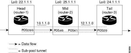
As shown in Figure 1, the tunnel configuration involves at least three devices—tunnel head, midpoint, and tail. On each of those devices one or two network interfaces must be configured for traffic ingress and egress.
Figure 1 Sample Tunnel Topology
Tunnel Head
At the device level:
Router-1# configure terminalEnter configuration commands, one per line. End with CNTL/Z.Router-1(config)# ip cef distributedRouter-1(config)# mpls traffic-eng tunnelsNow use the IS-IS commands on the left or the OSPF commands on the right
:
Router-1(config-router)# mpls traffic-eng router-id Loopback0Router-1(config-router)# exitNow resume the common command set.Router-1(config)# interface Loopback0At the virtual interface level:
Router-1(config-if)# ip address 22.1.1.1 255.255.255.255Router-1(config-if)# no ip directed-broadcastRouter-1(config-if)# exitAt the device level:
Router-1(config)# interface POS2/0/0At the physical interface level (egress):
Router-1(config-if)# ip address 10.1.1.1 255.255.255.0Router-1(config-if)# mpls traffic-eng tunnelsRouter-1(config-if)# ip rsvp bandwidth 130000 130000 sub-pool 80000If using IS-IS instead of OSPF:Router-1(config-if)# ip router isisIn all cases:Router-1(config-if)# exitAt the device level:
Router-1(config)# interface Tunnel1At the tunnel interface level:
Router-1(config-if)# bandwidth 110000Router-1(config-if)# ip unnumbered Loopback0Router-1(config-if)# tunnel destination 24.1.1.1Router-1(config-if)# tunnel mode mpls traffic-engRouter-1(config-if)# tunnel mpls traffic-eng priority 0 0Router-1(config-if)# tunnel mpls traffic-eng bandwidth sub-pool 30000Router-1(config-if)# tunnel mpls traffic-eng path-option 1 dynamicRouter-1(config)#Midpoint Devices
At the device level:
Router-2# configure terminalRouter-2(config)# ip cef distributedRouter-2(config)# mpls traffic-eng tunnelsNow use the IS-IS commands on the left or the OSPF commands on the right
:
router-2(config-router)# mpls traffic-eng router-id Loopback0router-2(config-router)# exitNow resume the common command set.Router-2(config)# interface Loopback0At the virtual interface level:
Router-2(config-if)# ip address 25.1.1.1 255.255.255.255Router-2(config-if)# no ip directed-broadcastRouter-2(config-if)# exitAt the device level:
router-1(config)# interface POS4/0Router-1(config-if)# ip address 11.1.1.2 255.255.255.0Router-1(config-if)# mpls traffic-eng tunnelsRouter-1(config-if)# ip rsvp bandwidth 130000 130000 sub-pool 80000If you are using IS-IS instead of OSPF:
Router-1(config-if)# ip router isisIn all cases:
Router-1(config-if)# exitAt the device level:
router-1(config)# interface POS4/1Router-1(config-if)# ip address 12.1.1.2 255.255.255.0Router-1(config-if)# mpls traffic-eng tunnelsRouter-1(config-if)# ip rsvp bandwidth 130000 130000 sub-pool 80000If you are using IS-IS instead of OSPF:
Router-1(config-if)# ip router isisIn all cases:
Router-1(config-if)# exitNote that there is no configuring of tunnel interfaces at the mid-point devices, only network interfaces and the device globally.
Tail-End Device
At the device level:
Router-3# configure terminalRouter-3(config)# ip cef distributedRouter-3(config)# mpls traffic-eng tunnelsNow use the IS-IS commands on the left or the OSPF commands on the right:
Router-3(config-router)# mpls traffic-eng router-id Loopback0Router-3(config-router)# exitNow resume the common command set.Router-3(config)# interface Loopback0At the virtual interface level:
Router-3(config-if)# ip address 24.1.1.1 255.255.255.255Router-3(config-if)# no ip directed-broadcastIf you are using IS-IS instead of OSPF:
Router-3(config-if)# ip router isisIn all cases:
Router-3(config-if)# exitAt the device level:
Router(config)# interface POS4/0Router-1(config-if)# ip address 12.1.1.3 255.255.255.0Router-1(config-if)# mpls traffic-eng tunnelsRouter-1(config-if)# ip rsvp bandwidth 130000 130000 sub-pool 80000If you are using IS-IS instead of OSPF:
Router-1(config-if)# ip router isisIn all cases:
Router-1(config-if)# exitGuaranteed Bandwidth Service Configuration
Having configured two bandwidth pools, you now can
•
•
Having a separate pool for traffic requiring strict guarantees allows you to limit the amount of such traffic admitted on any given link. Often it is possible to achieve strict QoS guarantees only if the amount of guaranteed traffic is limited to a portion of the total link bandwidth.
Having a separate pool for other traffic (best-effort or DiffServ traffic) allows you to have a separate limit for the amount of such traffic admitted on any given link. This is useful because it allows you to fill up links with best-effort/DiffServ traffic, thereby achieving a greater utilization of those links.
Providing Strict QoS Guarantees Using DS-TE Sub-pool Tunnels
A tunnel using sub-pool bandwidth can satisfy the stricter requirements if you do all of the following:
1.
If delay/jitter guarantees are sought, the DiffServ Expedited Forwarding queue (EF PHB) is used. You must configure the bandwidth of the queue to be at least equal to the bandwidth of the sub-pool.
If only bandwidth guarantees are sought, the DiffServ Assured Forwarding PHB (AF PHB) is used.
2.
You do this by marking the traffic that enters the tunnel with a unique value in the mpls exp bits field, and steering only traffic with that marking into the GB queue.
3.
You do this by rate-limiting the guaranteed traffic before it enters the sub-pool tunnel. The aggregate rate of all traffic entering the sub-pool tunnel should be less than or equal to the bandwidth capacity of the sub-pool tunnel. Excess traffic can be dropped (in the case of delay/jitter guarantees) or can be marked differently for preferential discard (in the case of bandwidth guarantees).
4.
You do this by setting the sub-pool bandwidth of each outbound link to the appropriate percentage of the total link bandwidth.
Providing Differentiated Service Using DS-TE Global Pool Tunnels
You can configure a tunnel using global pool bandwidth to carry best-effort as well as several other classes of traffic. Traffic from each class can receive differentiated service if you do all of the following:
1.
2.
3.
To control the amount of DiffServ tunnel traffic you intend to support on a given link, adjust the size of the global pool on that link.
Providing Strict Guarantees and Differentiated Service in the Same Network
Because DS-TE allows simultaneous constraint-based routing of sub-pool and global pool tunnels, strict guarantees and DiffServ can be supported simultaneously in a given network.
Guaranteed Bandwidth Service Examples
This section describes two example topologies in which Guaranteed Bandwidth Services can be supplied. They illustrate opposite ends of the spectrum of possibilities.
In the first example, the guaranteed bandwidth tunnel can be easily specified by its destination. The forwarding criteria refer to a single destination prefix.
In the second example, there can be many final destinations for the guaranteed bandwidth traffic, including a dynamically changing number of destination prefixes. The forwarding criteria are specified by Border Gateway Protocol (BGP) policies.
Example with Single Destination Prefix
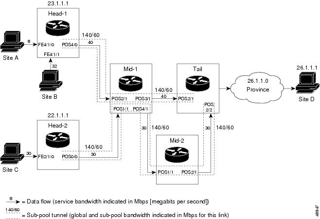
Figure 2 illustrates a topology for guaranteed bandwidth services whose destination is specified by a single prefix, either Site D (like a voice gateway, here bearing prefix 26.1.1.1) or a subnet (like the location of a web farm, here called "Province" and bearing prefix 26.1.1.0). Three services are offered:
•
•
•
Figure 2 Sample Topology for Guaranteed Bandwidth Services to a Single Destination Prefix
These three services run through two sub-pool tunnels:
•
•
Both tunnels use the same tail router, though they have different heads. (In Figure 2 one midpoint router is shared by both tunnels. There can be many more midpoints.)
All POS interfaces in this example are OC3, whose capacity is 155 Mbps.
Configuring Tunnel Head-1
First, recapitulate commands that establish two bandwidth pools and a sub-pool tunnel (as presented earlier in the "Configuration Examples" section. Then present the QoS commands that guarantee end-to-end service on the subpool tunnel. (With the Cisco 7500 router, Modular QoS CLI is used.)
Configuring the Pools and Tunnel
At the device level:
Router-1(config)# mpls traffic-eng tunnelsRouter-1config)# mpls traffic-eng tunnelsNow use the IS-IS commands on the left or the OSPF commands on the right
:
Router-1(config-router)# mpls traffic-eng router-id Loopback0Router-1(config-router)# exitNow resume the common command set.
Create a virtual interface:
Router-1(config)# interface Loopback0Router-1(config-if)# ip address 23.1.1.1 255.255.255.255Router-1(config-if)# no ip directed-broadcastRouter-1(config-if)# exitAt the outgoing physical interface:
Router-1(config)# interface pos4/0Router-1(config-if)# ip address 10.1.1.1 255.0.0.0Router-1(config-if)# mpls traffic-eng tunnelsRouter-1(config-if)# ip rsvp bandwidth 140000 140000 sub-pool 60000If you are using IS-IS instead of OSPF:
Router-1(config-if)# ip router isisIn all cases:
Router-1(config-if)# exitAt the tunnel interface:
Router-1(config)# interface Tunnel1Router-1(config-if)# bandwidth 110000Router-1(config-if)# ip unnumbered Loopback0Router-1(config-if)# tunnel destination 27.1.1.1Router-1(config-if)# tunnel mode mpls traffic-engRouter-1(config-if)# tunnel mpls traffic-eng priority 0 0Router-1(config-if)# tunnel mpls traffic-eng bandwidth sub-pool 40000Router-1(config-if)# tunnel mpls traffic-eng path-option 1 dynamicTo ensure that packets destined to host 26.1.1.1 and subnet 26.1.1.0 are sent into the sub-pool tunnel, create a static route. At the device level:
Router-1(config)# ip route 26.1.1.0 255.255.255.0 Tunnel1Router-1(config)# exitTo make sure that the Interior Gateway Protocol (IGP) will not send any other traffic down this tunnel, disable autoroute announce:
Router-1(config)# no tunnel mpls traffic-eng autoroute announceFor Service from Site A to Site D
At the inbound physical interface (FE4/1/0):
1.
class-map match-all sla-1-classmatch access-group 1002.
access-list 100 permit ip any host 26.1.1.13.
a.
–
–
–
b.
c.
d.
policy-map sla-1-input-policyclass sla-1-classpolice 8000000 1000000 2000000 conform-action set-mpls-exp-transmit 5 \ exceed-action dropclass class-defaultset-mpls-exp-transmit 04.
interface FastEthernet4/1/0service-policy input sla-1-input-policyFor Service from Site B to Subnet "Province"
At the inbound physical interface (FE4/1/1):
1.
class-map match-all sla-2-classmatch access-group 1202.
access-list 120 permit ip any 26.1.1.0 0.0.0.2553.
a.
–
–
–
b.
c.
d.
policy-map sla-2-input-policyclass sla-2-classpolice 32000000 1000000 2000000 conform-action set-mpls-exp-transmit 5 \ exceed-action dropclass class-defaultset-mpls-exp-transmit 04.
interface FastEthernet4/1/1service-policy input sla-2-input-policyFor Both Services
The outbound interface (POS4/0) is configured as follows:
1.
class-map match-all exp-5-trafficmatch mpls experimental 52.
policy-map output-interface-policyclass exp-5-trafficpriority 323.
interface POS4/0service-policy output output-interface-policyThe result of the above configuration lines is that packets entering the Head-1 router via interface FE4/1/0 destined to host 26.1.1.1, or entering the router via interface FE4/1/1 destined to subnet 26.1.1.0, will have their MPLS experimental bit set to 5. We assume that no other packets entering the router (on any interface) are using this value. (If this cannot be assumed, an additional configuration must be added to mark all such packets to another experimental value.) Packets marked with experimental bit 5, when exiting the router via interface POS4/0, will be placed into the priority queue.
Note
Configuring Tunnel Head-2
First, recapitulate commands that establish two bandwidth pools and a sub-pool tunnel (as presented earlier in the "Configuration Examples" section). Then present the QoS commands that guarantee end-to-end service on the sub-pool tunnel.
Configuring the Pools and Tunnel
At the device level:
Router-2(config)# ip cef distributedRouter-2(config)# mpls traffic-eng tunnelsNow use the IS-IS commands on the left or the OSPF commands on the right
:
Router-2(config-router)# mpls traffic-eng router-id Loopback0Router-2(config-router)# exitNow resume the common command set.Create a virtual interface:
Router-2(config)# interface Loopback0Router-2(config-if)# ip address 22.1.1.1 255.255.255.255Router-2(config-if)# no ip directed broadcastRouter-2(config-if)# exitAt the outgoing physical interface:
Router-2(config)# interface pos0/0Router-2(config-if)# ip address 11.1.1.1 255.0.0.0Router-2(config-if)# mpls traffic-eng tunnelsRouter-2(config-if)# ip rsvp bandwidth 140000 140000 sub-pool 60000If you are using IS-IS instead of OSPF:
Router-2(config-if)# ip router isisIn all cases:
Router-2(config-if)# exitAt the tunnel interface:
Router-2(config)# interface Tunnel2Router-2(config-if)# ip unnumbered Loopback0Router-2(config-if)# tunnel destination 27.1.1.1Router-2(config-if)# tunnel mode mpls traffic-engRouter-2(config-if)# tunnel mpls traffic-eng priority 0 0Router-2(config-if)# tunnel mpls traffic-eng bandwidth sub-pool 30000Router-2(config-if)# tunnel mpls traffic-eng path-option 1 dynamicRouter-2(config-if)# exitTo ensure that packets destined to subnet 26.1.1.0 are sent into the sub-pool tunnel, create a static route, at the device level:
Router-2(config)# ip route 26.1.1.0 255.255.255.0 Tunnel2Router-2(config)# exitFinally, in order to make sure that IGP will not send any other traffic down this tunnel, disable autoroute announce:
Router-2(config)# no tunnel mpls traffic-eng autoroute announceFor Service from Site C to Subnet "Province"
At the inbound physical interface (FE2/1/0):
1.
class-map match-all sla-3-classmatch access-group 1302.
access-list 130 permit ip any 26.1.1.0 0.0.0.2553.
a.
–
–
–
b.
c.
d.
policy-map sla-3-input-policyclass sla-3-classpolice 30000000 1000000 2000000 conform-action set-mpls-exp-transmit 5 \ exceed-action dropclass class-defaultset-mpls-exp-transmit 04.
interface FastEthernet2/1/0service-policy input sla-3-input-policyThe outbound interface POS0/0 is configured as follows:
1.
class-map match-all exp-5-trafficmatch mpls experimental 52.
policy-map output-interface-policyclass exp-5-trafficpriority 323.
interface POS0/0service-policy output output-interface-policyAs a result of all the above configuration lines, packets entering the Head-2 router via interface FE2/1/0 and destined for subnet 26.1.1.0 have their IP precedence field set to 5. It is assumed that no other packets entering this router (on any interface) are using this precedence. (If this cannot be assumed, an additional configuration must be added to mark all such packets with another precedence value.) When exiting this router via interface POS0/0, packets marked with precedence 5 are placed in the priority queue.
Note
Tunnel Midpoint Configuration [Mid-1]
All four interfaces on the midpoint router are configured identically to the outbound interface of the head router (except the IDs of the individual interfaces):
Configuring the Pools and Tunnels
At the device level:
Router-3(config)# ip cef distributedRouter-3(config)# mpls traffic-eng tunnelsNow use the IS-IS commands on the left or the OSPF commands on the right
:
Router-3(config-router)# mpls traffic-eng router-id Loopback0Router-3(config-router)# exitNow resume the common command set.
Create a virtual interface:
Router-3(config)# interface Loopback0Router-3(config-if)# ip address 24.1.1.1 255.255.255.255Router-3(config-if)# exitAt the physical interface level (ingress):
Router-3(config)# interface pos2/1Router-3(config-if)# ip address 10.1.1.2 255.0.0.0Router-3(config-if)# mpls traffic-eng tunnelsRouter-3(config-if)# ip rsvp bandwidth 140000 140000 sub-pool 60000If you are using IS-IS instead of OSPF:
Router-3(config-if)# ip router isisIn all cases:
Router-3(config-if)# exitRouter-3(config)# interface pos1/1Router-3(config-if)# ip address 11.1.1.2 255.0.0.0Router-3(config-if)# mpls traffic-eng tunnelsRouter-3(config-if)# ip rsvp bandwidth 140000 140000 sub-pool 60000If you are using IS-IS instead of OSPF:
Router-3(config-if)# ip router isisIn all cases:
Router-3(config-if)# exitAt the physical interface level (egress):
Router-3(config)# interface pos3/1Router-3(config-if)# ip address 12.1.1.1 255.0.0.0Router-3(config-if)# mpls traffic-eng tunnelsRouter-3(config-if)# ip rsvp bandwidth 140000 140000 sub-pool 60000If you are using IS-IS instead of OSPF:
Router-3(config-if)# ip router isisIn all cases:
Router-3(config-if)# exitRouter-3(config)# interface pos4/1Router-3(config-if)# ip address 13.1.1.1 255.0.0.0Router-3(config-if)# mpls traffic-eng tunnelsRouter-3(config-if)# ip rsvp bandwidth 140000 140000 sub-pool 60000If you are using IS-IS instead of OSPF:
Router-3(config-if)# ip router isisIn all cases:
Router-3(config-if)# exitTunnel Midpoint Configuration [Mid-2]
Both interfaces on the midpoint router are configured identically to the outbound interface of the head router (except, of course, for the IDs of the individual interfaces):
Configuring the Pools and Tunnel
At the device level:
Router-5(config)# ip cef distributedRouter-5(config)# mpls traffic-eng tunnelsUse the IS-IS commands on the left or the OSPF commands on the right
:
Router-5(config-router)# mpls traffic-eng router-id Loopback0Router-5(config-router)# exitNow resume the common command set.Create a virtual interface:
Router-5(config)# interface Loopback0Router-5(config-if)# ip address 25.1.1.1 255.255.255.255Router-5(config-if)# exitAt the physical interface level (ingress):
Router-5(config)# interface pos1/1Router-5(config-if)# ip address 13.1.1.2 255.0.0.0Router-5(config-if)# mpls traffic-eng tunnelsRouter-5(config-if)# ip rsvp bandwidth 140000 140000 sub-pool 60000If you are using IS-IS instead of OSPF:
Router-5(config-if)# ip router isisIn all cases:
Router-5(config-if)# exitAt the physical interface level (egress):
Router-5(config)# interface pos2/1Router-5(config-if)# ip address 14.1.1.1 255.0.0.0Router-5(config-if)# mpls traffic-eng tunnelsRouter-5(config-if)# ip rsvp bandwidth 140000 140000 sub-pool 60000If you are using IS-IS instead of OSPF:
Router-5(config-if)# ip router isisIn all cases:
Router-5(config-if)# exitTunnel Tail Configuration
The inbound interfaces on the tail router are configured identically to the inbound interfaces of the midpoint routers (except the ID of each particular interface):
Configuring the Pools and Tunnels
At the device level:
Router-4(config)# ip cef distributedRouter-4(config)# mpls traffic-eng tunnelsUse the IS-IS commands on the left or the OSPF commands on the right:
Router-4(config-router)# mpls traffic-eng router-id Loopback0Router-4(config-router)# exitNow resume the common command set.Create a virtual interface:
Router-4(config)# interface Loopback0Router-4(config-if)# ip address 27.1.1.1 255.255.255.255Router-4(config-if)# exitAt the physical interface (ingress):
Router-4(config)# interface pos2/1Router-4(config-if)# ip address 12.1.1.2 255.0.0.0Router-4(config-if)# mpls traffic-eng tunnelsRouter-4(config-if)# ip rsvp bandwidth 140000 140000 sub-pool 60000If you are using IS-IS instead of OSPF:
Router-4(config-if)# ip router isisIn all cases:
Router-4(config-if)# exitRouter-4(config)# interface pos2/2Router-4(config-if)# ip address 14.1.1.2 255.0.0.0Router-4(config-if)# mpls traffic-eng tunnelsRouter-4(config-if)# ip rsvp bandwidth 140000 140000 sub-pool 60000If you are using IS-IS instead of OSPF:
Router-4(config-if)# ip router isisIn all cases:
Router-4(config-if)# exitBecause the tunnel ends on the tail (does not include any outbound interfaces of the tail router), no outbound QoS configuration is used.
Example with Many Destination Prefixes
Figure 3 illustrates a topology for guaranteed bandwidth services whose destinations are a set of prefixes. Those prefixes usually share some common properties such as belonging to the same autonomous system (AS) or transiting through the same AS. Although the individual prefixes may change dynamically because of route flaps in the downstream autonomous systems, the properties the prefixes share will not change. Policies addressing the destination prefix set are enforced through Border Gateway Protocol (BGP), which is described in the following documents:
•
•
•
In this example, three guaranteed bandwidth services are offered, each coming through a Cisco 7500 or a Cisco 12000 edge device:
•
•
•
Figure 3 Sample Topology for Guaranteed Bandwidth Service to Many Destination Prefixes
The applicability of guaranteed bandwidth service is not limited to the three types of multiple destination scenarios described above. There is not room in this document to present all possible scenarios. These three were chosen as representative of the wide range of possible deployments.
The guaranteed bandwidth services run through two sub-pool tunnels:
•
•
In addition, a global pool tunnel has been configured from each head end, to carry best-effort traffic to the same destinations. All four tunnels use the same tail router, even though they have different heads and differ in their passage through the midpoints. (In reality, there would be many more midpoints than just the two shown here.)
All POS interfaces in this example are OC3, whose capacity is 155 Mbps.
Configuring a multi-destination guaranteed bandwidth service involves:
1.
2.
3.
4.
All of these tasks are included in the following example.
Configuration of Tunnel Head-1
First recapitulate commands that establish a sub-pool tunnel (commands presented earlier) and now configure a global pool tunnel. Additionally, we present QoS and BGP commands that guarantee end-to-end service on the sub-pool tunnel. (With the Cisco 7500(VIP) router, Modular QoS CLI is used).
Configuring the Pools and Tunnels
At the device level:
router-1(config)# ip cef distributedrouter-1(config)# mpls traffic-eng tunnelsUse the IS-IS commands on the left or the OSPF commands on the right
:
router-1(config-router)# mpls traffic-eng router-id Loopback0router-1(config-router)# exitNow resume the common command set.Create a virtual interface:
router-1(config)# interface Loopback0router-1(config-if)# ip address 23.1.1.1 255.255.255.255router-1(config-if)# exitAt the outgoing physical interface:
router-1(config)# interface pos4/0router-1(config-if)# ip address 10.1.1.1 255.0.0.0router-1(config-if)# mpls traffic-eng tunnelsrouter-1(config-if)# ip rsvp bandwidth 140000 140000 sub-pool 60000If you are using IS-IS instead of OSPF:
router-1(config-if)# ip router isisIn all cases:
router-1(config-if)# exitAt one tunnel interface, create a sub-pool tunnel:
router-1(config)# interface Tunnel1router-1(config-if)# ip unnumbered Loopback0router-1(config-if)# tunnel destination 27.1.1.1router-1(config-if)# tunnel mode mpls traffic-engrouter-1(config-if)# tunnel mpls traffic-eng priority 0 0router-1(config-if)# tunnel mpls traffic-eng bandwidth sub-pool 40000router-1(config-if)# tunnel mpls traffic-eng path-option 1 explicit name gbs-path1router-1(config-if)# exitAt a second tunnel interface, create a global pool tunnel:
router-1(config)# interface Tunnel2router-1(config-if)# ip unnumbered Loopback0router-1(config-if)# tunnel destination 27.1.1.1router-1(config-if)# tunnel mode mpls traffic-engrouter-1(config-if)# tunnel mpls traffic-eng priority 0 0router-1(config-if)# tunnel mpls traffic-eng bandwidth 80000router-1(config-if)# tunnel mpls traffic-eng path-option 1 explicit name \ best-effort-path1router-1(config-if)# exitIn this example explicit paths are used instead of dynamic, to ensure that best-effort traffic and guaranteed bandwidth traffic will travel along different paths.
At the device level:
router-1(config)# ip explicit-path name gbs-path1router-1(config-ip-expl-path)# next-address 24.1.1.1router-1(config-ip-expl-path)# next-address 27.1.1.1router-1(config-ip-expl-path)# exitrouter-1(config)# ip explicit-path name best-effort-path1router-1(config-ip-expl-path)# next-address 24.1.1.1router-1(config-ip-expl-path)# next-address 25.1.1.1router-1(config-ip-expl-path)# next-address 27.1.1.1router-1(config-ip-expl-path)# exitNote that autoroute is not used, as that could cause the IGP to send other traffic down these tunnels.
Configuring DiffServ QoS
At the inbound physical interface (in Figure 3 this is FE4/1/0), packets received are rate-limited to:
a.
b.
c.
Packets that are mapped to qos-group 6 and that conform to the rate-limit are marked with experimental value 5 and the BGP destination community string, and are forwarded; packets that do not conform (exceed action) are dropped:
router-1(config)# interface FastEthernet4/1/0router-1(config-if)# rate-limit input qos-group 6 30000000 1000000 2000000 \ conform-action set-mpls-exp-transmit 5 exceed-action droprouter-1(config-if)# bgp-policy destination ip-qos-maprouter-1(config-if)# exitAt the device level create a class of traffic called "exp5-class" that has MPLS experimental bit set to 5:
router-1(config)# class-map match-all exp5-classrouter-1(config-cmap)# match mpls experimental 5router-1(config-cmap)# exitCreate a policy that creates a priority queue for "exp5-class":
router-1(config)# policy-map core-out-policyrouter-1(config-pmap)# class exp5-classrouter-1(config-pmap-c)# priority 100000router-1(config-pmap-c)# exitrouter-1(config-pmap)# class class-defaultrouter-1(config-pmap-c)# bandwidth 55000router-1(config-pmap-c)# exitrouter-1(config-pmap)# exitThe policy is applied to packets exiting the outbound interface POS4/0.
router-1(config)# interface POS4/0router-1(config-if)# service-policy output core-out-policyConfiguring QoS Policy Propagation via BGP
For All GB Services
Create a table map under BGP to map (tie) the prefixes to a qos-group. At the device level:
router-1(config)# ip bgp-community new-formatrouter-1(config)# router bgp 2router-1(config-router)# no synchronizationrouter-1(config-router)# table-map set-qos-grouprouter-1(config-router)# bgp log-neighbor-changesrouter-1(config-router)# neighbor 27.1.1.1 remote-as 2router-1(config-router)# neighbor 27.1.1.1 update-source Loopback0router-1(config-router)# no auto-summaryrouter-1(config-router)# exitFor GB Service Destined to AS5
Create a distinct route map for this service. This includes setting the next-hop of packets matching 29.1.1.1 so they will be mapped onto Tunnel #1 (the guaranteed bandwidth service tunnel). At the device level:
router-1(config)# route-map set-qos-group permit 10router-1(config-route-map)# match as-path 100router-1(config-route-map)# set ip qos-group 6router-1(config-route-map)# set ip next-hop 29.1.1.1router-1(config-route-map)# exitrouter-1(config)# ip as-path access-list 100 permit ^5$For GB Service Transiting through AS5
Create a distinct route map for this service. (Its traffic will go to AS6 and AS7).
At the device level:
router-1(config)# route-map set-qos-group permit 10router-1(config-route-map)# match as-path 101router-1(config-route-map)# set ip qos-group 6router-1(config-route-map)# set ip next-hop 29.1.1.1router-1(config-route-map)# exitrouter-1(config)# ip as-path access-list 101 permit _5_For GB Service Destined to Community 100:1
Create a distinct route map for all traffic destined to prefixes that have community value 100:1. This traffic will go to AS3, AS5, and AS8.
At the device level:
router-1(config)# route-map set-qos-group permit 10router-1(config-route-map)# match community 20router-1(config-route-map)# set ip qos-group 6router-1(config-route-map)# set ip next-hop 29.1.1.1router-1(config-route-map)# exitrouter-1(config)# ip community-list 20 permit 100:1Mapping Traffic onto the Tunnels
Map all guaranteed bandwidth traffic onto Tunnel #1:
router-1(config)# ip route 29.1.1.1 255.255.255.255 Tunnel1Map all best-effort traffic onto Tunnel #2:
router-1(config)# ip route 30.1.1.1 255.255.255.255 Tunnel2Configuration of Tunnel Head-2
As with the Head-1 device and interfaces, the following Head-2 configuration first presents commands that establish a sub-pool tunnel (commands presented earlier) and then also configures a global pool tunnel. After that it presents QoS and BGP commands that guarantee end-to-end service on the sub-pool tunnel. (Because this is a Cisco 7500 (VIP) router, Modular QoS CLI is used).
Configuring the Pools and Tunnels
At the device level:
router-2(config)# ip cef distributedrouter-2(config)# mpls traffic-eng tunnelsUse the IS-IS commands on the left or the OSPF commands on the right
:
router-2(config-router)# mpls traffic-eng router-id Loopback0router-2(config-router)# exitNow resume the common command set.Create a virtual interface:
router-2(config)# interface Loopback0router-2(config-if)# ip address 22.1.1.1 255.255.255.255router-2(config-if)# exitAt the outgoing physical interface:
router-2(config)# interface pos0/0router-2(config-if)# ip address 11.1.1.1 255.0.0.0router-2(config-if)# mpls traffic-eng tunnelsrouter-2(config-if)# ip rsvp bandwidth 140000 140000 sub-pool 60000If you are using IS-IS instead of OSPF:
router-2(config-if)# ip router isisIn all cases:
router-2(config-if)# exitAt one tunnel interface, create a sub-pool tunnel:
router-2(config)# interface Tunnel3router-2(config-if)# ip unnumbered Loopback0router-2(config-if)# tunnel destination 27.1.1.1router-2(config-if)# tunnel mode mpls traffic-engrouter-2(config-if)# tunnel mpls traffic-eng priority 0 0router-2(config-if)# tunnel mpls traffic-eng bandwidth sub-pool 30000router-2(config-if)# tunnel mpls traffic-eng path-option 1 explicit name gbs-path2router-2(config-if)# exitAt a second tunnel interface, create a global pool tunnel:
router-2(config)# interface Tunnel4router-2(config-if)# ip unnumbered Loopback0router-2(config-if)# tunnel destination 27.1.1.1router-2(config-if)# tunnel mode mpls traffic-engrouter-2(config-if)# tunnel mpls traffic-eng priority 0 0router-2(config-if)# tunnel mpls traffic-eng bandwidth 70000router-2(config-if)# tunnel mpls traffic-eng path-option 1 explicit name \ best-effort-path2router-2(config-if)# exitIn this example explicit paths are used instead of dynamic, to ensure that best-effort traffic and guaranteed bandwidth traffic will travel along different paths.
At the device level:
router-2(config)# ip explicit-path name gbs-path2router-2(config-ip-expl-path)# next-address 24.1.1.1router-2(config-ip-expl-path)# next-address 27.1.1.1router-2(config-ip-expl-path)# exitrouter-2(config)# ip explicit-path name best-effort-path2router-2(config-ip-expl-path)# next-address 24.1.1.1router-2(config-ip-expl-path)# next-address 25.1.1.1router-2(config-ip-expl-path)# next-address 27.1.1.1router-2(config-ip-expl-path)# exitNote that autoroute is not used, as that could cause the IGP to send other traffic down these tunnels.
Configuring DiffServ QoS
At the inbound physical interface (in Figure 3 this is FE2/1), packets received are rate-limited to:
a.
b.
c.
Packets that are mapped to qos-group 6 and that conform to the rate-limit are marked with experimental value 5 and the BGP destination community string, and are forwarded; packets that do not conform (exceed action) are dropped:
router-2(config)# interface FastEthernet2/1router-2(config-if)# rate-limit input qos-group 6 30000000 1000000 2000000 \ conform-action set-mpls-exp-transmit 5 exceed-action droprouter-2(config-if)# bgp-policy destination ip-qos-maprouter-1(config-if)# exitAt the device level create a class of traffic called "exp5-class" that has MPLS experimental bit set to 5:
router-2(config)# class-map match-all exp5-classrouter-2(config-cmap)# match mpls experimental 5router-2(config-cmap)# exitCreate a policy that creates a priority queue for "exp5-class":
router-2(config)# policy-map core-out-policyrouter-2(config-pmap)# class exp5-classrouter-2(config-pmap-c)# priority 100000router-2(config-pmap-c)# exitrouter-2(config-pmap)# class class-defaultrouter-2(config-pmap-c)# bandwidth 55000router-2(config-pmap-c)# exitrouter-2(config-pmap)# exitThe policy is applied to packets exiting interface POS0/0:
interface POS0/0service-policy output core-out-policyAs a result of all the above configuration lines, packets entering the Head-2 router via interface FE2/1 and destined for AS5, BGP community 100:1, or transiting AS5 will have their experimental field set to 5. It is assumed that no other packets entering this router (on any interface) are using this exp bit value. (If this cannot be assumed, an additional configuration must be added to mark all such packets with another experimental value.) When exiting this router via interface POS0/0, packets marked with experimental value 5 are placed into the priority queue.
Note
Configuring QoS Policy Propagation via BGP
For All GB Services
Create a table map under BGP to map (tie) the prefixes to a qos-group. At the device level:
router-2(config)# ip bgp-community new-formatrouter-2(config)# router bgp 2router-2(config-router)# no synchronizationrouter-2(config-router)# table-map set-qos-grouprouter-2(config-router)# bgp log-neighbor-changesrouter-2(config-router)# neighbor 27.1.1.1 remote-as 2router-2(config-router)# neighbor 27.1.1.1 update-source Loopback0router-2(config-router)# no auto-summaryrouter-2(config-router)# exitFor GB Service Destined to AS5
Create a distinct route map for this service. This includes setting the next-hop of packets matching 29.1.1.1 so they will be mapped onto Tunnel #3 (the guaranteed bandwidth service tunnel). At the device level:
router-2(config)# route-map set-qos-group permit 10router-2(config-route-map)# match as-path 100router-2(config-route-map)# set ip qos-group 6router-2(config-route-map)# set ip next-hop 29.1.1.1router-2(config-route-map)# exitrouter-2(config)# ip as-path access-list 100 permit ^5$For GB Service Transiting through AS5
Create a distinct route map for this service. (Its traffic will go to AS6 and AS7).
At the device level:
router-2(config)# route-map set-qos-group permit 10router-2(config-route-map)# match as-path 101router-2(config-route-map)# set ip qos-group 6router-2(config-route-map)# set ip next-hop 29.1.1.1router-2(config-route-map)# exitrouter-2(config)# ip as-path access-list 101 permit _5_For GB Service Destined to Community 100:1
Create a distinct route map for all traffic destined to prefixes that have community value 100:1. This traffic will go to AS3, AS5, and AS8.
At the device level:
router-2(config)# route-map set-qos-group permit 10router-2(config-route-map)# match community 20router-2(config-route-map)# set ip qos-group 6router-2(config-route-map)# set ip next-hop 29.1.1.1router-2(config-route-map)# exitrouter-2(config)# ip community-list 20 permit 100:1Mapping the Traffic onto the Tunnels
Map all guaranteed bandwidth traffic onto Tunnel #3:
router-2(config)# ip route 29.1.1.1 255.255.255.255 Tunnel3Map all best-effort traffic onto Tunnel #4:
router-2(config)# ip route 30.1.1.1 255.255.255.255 Tunnel4Tunnel Midpoint Configuration [Mid-1]
All four interfaces on the midpoint router are configured very much like the outbound interface of the head router. The strategy is to have all mid-point routers in this autonomous system ready to carry future as well as presently configured sub-pool and global pool tunnels.
Configuring the Pools and Tunnels
At the device level:
router-3(config)# ip cef distributedrouter-3(config)# mpls traffic-eng tunnelsNow use the IS-IS commands on the left or the OSPF commands on the right:
router-3(config-router)# mpls traffic-eng router-id Loopback0router-3(config-router)# exitNow resume the common command set.Create a virtual interface:
router-3(config)# interface Loopback0router-3(config-if)# ip address 24.1.1.1 255.255.255.255router-3(config-if)# exitAt the physical interface level (ingress):
router-3(config)# interface pos2/1router-3(config-if)# ip address 10.1.1.2 255.0.0.0router-3(config-if)# mpls traffic-eng tunnelsrouter-3(config-if)# ip rsvp bandwidth 140000 140000 sub-pool 70000If you are using IS-IS instead of OSPF:router-3(config-if)# ip router isisIn all cases:router-3(config-if)# exitrouter-3(config)# interface pos1/1router-3(config-if)# ip address 11.1.1.2 255.0.0.0router-3(config-if)# mpls traffic-eng tunnelsrouter-3(config-if)# ip rsvp bandwidth 140000 140000 sub-pool 70000If you are using IS-IS instead of OSPF:router-3(config-if)# ip router isisIn all cases:router-3(config-if)# exitAt the physical interface level (egress), through which two sub-pool tunnels currently exit:
router-3(config)# interface pos3/1router-3(config-if)# ip address 12.1.1.1 255.0.0.0router-3(config-if)# mpls traffic-eng tunnelsrouter-3(config-if)# ip rsvp bandwidth 140000 140000 sub-pool 70000If you are using IS-IS instead of OSPF:router-3(config-if)# ip router isisIn all cases:router-3(config-if)# exitAt the physical interface level (egress), through which two global pool tunnels currently exit:
router-3(config)# interface pos4/1router-3(config-if)# ip address 13.1.1.1 255.0.0.0router-3(config-if)# mpls traffic-eng tunnelsrouter-3(config-if)# ip rsvp bandwidth 140000 140000 sub-pool 70000If using IS-IS instead of OSPF:router-3(config-if)# ip router isisIn all cases:router-3(config-if)# exitTunnel Midpoint Configuration [Mid-2]
Both interfaces on this midpoint router are configured like the outbound interfaces of the Mid-1 router.
Configuring the Pools and Tunnels
At the device level:
router-5(config)# ip cef distributedrouter-5(config)# mpls traffic-eng tunnelsNow use the IS-IS commands on the left or the OSPF commands on the right:
router-5(config-router)# mpls traffic-eng router-id Loopback0router-5(config-router)# exitNow resume the common command set.Create a virtual interface:
router-5(config)# interface Loopback0router-5(config-if)# ip address 25.1.1.1 255.255.255.255router-5(config-if)# exitAt the physical interface level (ingress):
router-5(config)# interface pos1/1router-5(config-if)# ip address 13.1.1.2 255.0.0.0router-5(config-if)# mpls traffic-eng tunnelsrouter-5(config-if)# ip rsvp bandwidth 140000 140000 sub-pool 70000If using IS-IS instead of OSPF:
router-5(config-if)# ip router isisIn all cases:
router-5(config-if)# exitAt the physical interface level (egress):
router-5(config)# interface pos2/1router-5(config-if)# ip address 14.1.1.1 255.0.0.0router-5(config-if)# mpls traffic-eng tunnelsrouter-5(config-if)# ip rsvp bandwidth 140000 140000 sub-pool 70000If using IS-IS instead of OSPF:
router-5(config-if)# ip router isisIn all cases:
router-5(config-if)# exit
Tunnel Tail Configuration
The inbound interfaces on the tail router are configured much like the outbound interfaces of the midpoint routers:
Configuring the Pools and Tunnels
At the device level:
router-4(config)# ip cef distributedrouter-4(config)# mpls traffic-eng tunnelsUse the IS-IS commands on the left or the OSPF commands on the right. In the case of OSPF, advertise two new loopback interfaces—29.1.1.1 and 30.1.1.1 in our example—which are defined in the "Configuring QoS Policy Propagation" section
:
router-4(config-router)# mpls traffic-eng router-id Loopback0router-4(config-router)# mpls traffic-eng router-id Loopback1router-4(config-router)# mpls traffic-eng router-id Loopback2router-4(config-router)# exitNow resume the common command set.Create a virtual interface:
router-4(config)# interface Loopback0router-4(config-if)# ip address 27.1.1.1 255.255.255.255router-4(config-if)# exitAt the physical interface (ingress):
router-4(config)# interface pos2/1router-4(config-if)# ip address 12.1.1.2 255.0.0.0router-4(config-if)# mpls traffic-eng tunnelsrouter-4(config-if)# ip rsvp bandwidth 140000 140000 sub-pool 70000If you are using IS-IS instead of OSPF:router-4(config-if)# ip router isisIn all cases:router-4(config-if)# exitrouter-4(config)# interface pos2/2router-4(config-if)# ip address 14.1.1.2 255.0.0.0router-4(config-if)# mpls traffic-eng tunnelsrouter-4(config-if)# ip rsvp bandwidth 140000 140000 sub-pool 70000If you are using IS-IS instead of OSPF:router-4(config-if)# ip router isisIn all cases:router-4(config-if)# exitConfiguring QoS Policy Propagation
On the tail device, you must configure a separate virtual loopback IP address for each class-of-service terminating here. The headend routers need these addresses to map traffic into the proper tunnels. In the current example, four tunnels terminate on the same tail device but they represent only two service classes, so only two additional loopback addresses are needed:
Create two virtual interfaces:
router-4(config)# interface Loopback1router-4(config-if)# ip address 29.1.1.1 255.255.255.255If you are using IS-IS instead of OSPF:router-4(config-if)# ip router isisIn all cases:router-4(config-if)# exitrouter-4(config)# interface Loopback2router-4(config-if)# ip address 30.1.1.1 255.255.255.255If you are using IS-IS instead of OSPF:router-4(config-if)# ip router isisIn all cases:router-4(config-if)# exitAt the device level, configure BGP to send the community to each tunnel head:
router-4(config)# ip bgp-community new-formatrouter-4(config)# router bgp 2router-4(config-router)# neighbor 23.1.1.1 send-communityrouter-4(config-router)# neighbor 22.1.1.1 send-communityrouter-4(config-router)# exitCommand Reference
This section describes the following modified commands:
•
•
•
•
•
•
All other commands used with this feature are documented in the Cisco IOS Release 12.2 command reference publications.
ip rsvp bandwidth
To enable Resource Reservation Protocol (RSVP) for IP on an interface, use the ip rsvp bandwidth command in interface configuration mode. To disable RSVP completely, use the no form of this command. To eliminate only the sub-pool portion of the bandwidth, use the no form of this command with the keyword sub-pool.
ip rsvp bandwidth interface-kbps single-flow-kbps [sub-pool kbps]
no ip rsvp bandwidth interface-kbps single-flow-kbps [sub-pool kbps]
Syntax Description
Defaults
RSVP is disabled if this command is not entered. When enabled without the optional arguments, RSVP is enabled and 75 percent of the link bandwidth is reserved for it.
Command Modes
Interface configuration
Command History
Usage Guidelines
RSVP cannot be configured with VIP-distributed Cisco Express Forwarding (dCEF).
RSVP is disabled by default to allow backward compatibility with systems that do not implement RSVP.
Weighted Random Early Detection (WRED) or fair queueing must be enabled first.
Related Commands
mpls traffic-eng backup-path tunnel
To configure the physical interface to use a backup tunnel in the event of a detected failure on that interface, use the mpls traffic-eng backup tunnel command in interface configuration mode.
mpls traffic-eng backup-path tunnelinterface
Syntax Description
Defaults
No default behavior or values.
Command Modes
Interface configuration
Command History
Examples
The following example shows you how to specify the traffic engineering backup tunnel with the identifier 1000:
Router(config_if)# mpls traffic-eng backup-path Tunnel1000Related Commands
show mpls traffic-eng fast-reroute database
To display the contents of the Fast Reroute (FRR) database, use the show mpls traffic-eng fast-reroute database command in EXEC mode.
show mpls traffic-eng fast-reroute database [{network [mask | masklength] | labels low label [-high label] | interface ifname [backup-interface ifname ] | backup-interface ifname}] [state {active | ready | partial | complete}]
[role {head | middle}][detail]Syntax Description
Defaults
No default behavior or values.
Command Modes
EXEC
Command History
Examples
The following example shows output from the show mpls traffic-eng fast-reroute database command at a tunnel head link:
Router# show mpls traffic-eng fast-reroute database 12.0.0.0Tunnel head fast reroute information:Prefix Tunnel In-label Out intf/label FRR intf/label Status12.0.0.0/16 Tu111 Tun hd PO0/0:Untagged Tu4000:16 ready12.0.0.0/16 Tu449 Tun hd PO0/0:Untagged Tu4000:736 ready12.0.0.0/16 Tu314 Tun hd PO0/0:Untagged Tu4000:757 ready12.0.0.0/16 Tu313 Tun hd PO0/0:Untagged Tu4000:756 readyTable 1 describes significant fields shown in the display.
The following example shows output from the show mpls traffic-eng fast-reroute database command with the labels keyword specified at a midpoint link:
Router# show mpls traffic-eng fast-reroute database labels 250 - 255Tunnel head fast reroute information:Prefix Tunnel In-label Outintf/label FRR intf/label StatusLSP midpoint frr information:LSP identifier In-label Out intf/label FRR intf/label Status10.110.0.10 229 [7334] 255 PO0/0:694 Tu4000:694 active10.110.0.10 228 [7332] 254 PO0/0:693 Tu4000:693 active10.110.0.10 227 [7331] 253 PO0/0:692 Tu4000:692 active10.110.0.10 226 [7334] 252 PO0/0:691 Tu4000:691 active10.110.0.10 225 [7333] 251 PO0/0:690 Tu4000:690 active10.110.0.10 224 [7329] 250 PO0/0:689 Tu4000:689 activeThe following example shows output from the show mpls traffic-eng fast-reroute database command with the detail keyword included at a tunnel head link:
Router# show mpls traffic-eng fast-reroute database 12.0.0.0. detailLFIB FRR Database Summary:Total Clusters: 2Total Groups: 2Total Items: 789Link 10:PO5/0 (Down, 1 group)Group 51:PO5/0->Tu4000 (Up, 779 members)Prefix 12.0.0.0/16, Tu313, activeInput label Tun hd, Output label PO0/0:773, FRR label Tu4000:773Prefix 12.0.0.0/16, Tu392, activeInput label Tun hd, Output label PO0/0:775, FRR label Tu4000:775Prefix 12.0.0.0/16, Tu111, activeInput label Tun hd, Output label PO0/0:16, FRR label Tu4000:16Prefix 12.0.0.0/16, Tu394, activeInput label Tun hd, Output label PO0/0:774, FRR label Tu4000:774Table 2 describes significant fields when the detail keyword is used.
Related Commands
show mpls traffic-eng fast-reroute log reroutes
Displays contents of Fast Reroute event log.
show mpls traffic-eng fast-reroute log reroutes
To display the contents of the Fast Reroute event log, use the show mpls traffic-eng fast-reroute log reroutes command in EXEC mode.
show mpls traffic-eng fast-reroute log reroutes
Syntax Description
This command has no arguments or keywords.
Defaults
No default behavior or values.
Command Modes
EXEC
Command History
Examples
The following example shows output from the show mpls traffic-eng fast-reroute log reroutes command:
Router# show mpls traffic-eng fast-reroute log reroutesWhen Interface Event Rewrites Duration CPU msecs Suspends Errors00:27:39 PO0/0 Down 1079 30 msecs 30 0 000:27:35 PO0/0 Up 1079 40 msecs 40 0 0Table 3 describes significant fields shown in the display.
show mpls traffic-eng topology
To show the MPLS traffic engineering global topology as currently known at this node, use the show mpls traffic-eng topology command in privileged EXEC mode.
show mpls traffic-eng topology [{A.B.C.D | igp-id {isis nsapaddr | ospf A.B.C.D}] [brief]
Syntax Description
Defaults
No default behavior or values.
Command Modes
Privileged EXEC
Command History
Examples
The following example shows output from the show mpls traffic-eng topology command:
Router# show mpls traffic-eng topologyMy_System_id: 0000.0025.0003.00IGP Id: 0000.0024.0004.00, MPLS TE Id:24.4.4.4 Router Nodelink[0 ]:Intf Address: 150.1.1.4Nbr IGP Id: 0000.0024.0004.02,admin_weight:10, affinity_bits:0x0max_link_bw:10000 max_link_reservable: 10000globalpoolsubpooltotal allocated reservable reservable--------------- ---------- ----------bw[0]: 0 1000 500bw[1]: 10 990 490bw[2]: 600 390 390bw[3]: 0 390 390bw[4]: 0 390 390bw[5]: 0 390 390Table 4 describes significant fields shown in the display.
tunnel mpls traffic-eng bandwidth
To configure bandwidth required for a Multiprotocol Label Switching (MPLS) traffic engineering tunnel, use the tunnel mpls traffic-eng bandwidth command in interface configuration mode. To disable this feature, use the no form of this command.
tunnel mpls traffic-eng bandwidth {sub-pool | [global]} bandwidth
no tunnel mpls traffic-eng bandwidth {sub-pool | [global]} bandwidth
Syntax Description
Defaults
Default bandwidth is 0.
Default is a global pool tunnel.
Command Modes
Interface configuration
Command History
Usage Guidelines
Enter the bandwidth for either a global pool or sub-pool tunnel, not both. Only the ip rsvp bandwidth command specifies the two bandwidths within one command.
To set up only a global pool tunnel, leave out the keyword sub-pool. If you enter global as a keyword, the system will accept it, but will not write it to NVRAM. This is to avoid the problem of having your configuration not understood if you upgrade to an image that contains the DS-TE capability and then return to a non DS-TE image.
Related Commands
tunnel mpls traffic-eng fast-reroute
To enable a Multiprotocol Label Switching (MPLS) traffic engineering tunnel to use a backup tunnel in the event of a link failure if a backup tunnel exists, use the tunnel mpls traffic-eng fast-reroute command in interface configuration mode.
tunnel mpls traffic-eng fast-reroute
Syntax Description
This command has no arguments or keywords.
Defaults
No default behavior or values.
Command Modes
Interface configuration
Command History
Examples
The following example enables an MPLS traffic engineering tunnel to use a backup tunnel if a link fails and a backup tunnel exists:
Router(config_if)# tunnel mpls traffic-eng fast-rerouteRelated Commands
Glossary
CBR—Constraint Based Routing. The computation of traffic paths that simultaneously satisfy label-switched path attributes and current network resource limitations.
CEF—Cisco Express Forwarding. A means for accelerating the forwarding of packets within a router, by storing route lookup information in several data structures instead of in a route cache.
CLI—Command Line Interface. Cisco's interface for configuring and managing its routers.
DS-TE—Diff Serv-aware Traffic Engineering. The capability to configure two bandwidth pools on each link, a global pool and a sub-pool. MPLS traffic engineering tunnels using the sub-pool bandwidth can be configured with Quality of Service mechanisms to deliver guaranteed bandwidth services end-to-end across the network. Simultaneously, tunnels using the global pool can convey DiffServ traffic.
flooding—A traffic passing technique used by switches and bridges in which traffic received on an interface is sent out through all of the interfaces of that device except the interface on which the information was originally received.
GB queue—Guaranteed Bandwidth queue. A per-hop behavior (PHB) used exclusively by the strict guarantee traffic. If delay/jitter guarantees are sought, the diffserv Expedited Forwarding queue (EF PHB) is used. If only bandwidth guarantees are sought, the diffserv Assured Forwarding PHB (AF PHB) is used.
Global Pool—The total bandwidth allocated to an MPLS traffic engineering link.
IGP—Interior Gateway Protocol. An internet protocol used to exchange routing information within an autonomous system. Examples of common internet IGPs include IGRP, OSPF, and RIP.
label-switched path (LSP) tunnel—A configured connection between two routers, using label switching to carry the packets.
LCAC—Link-level (per-hop) call admission control.
LSP—Label-switched path (see above).
Also Link-state packet—A broadcast packet used by link-state protocols that contains information about neighbors and path costs. LSPs are used by the receiving routers to maintain their routing tables. Also called link-state advertisement (LSA).MPLS—Multi-Protocol Label Switching (formerly known as Tag Switching). A method for directing packets primarily through Layer 2 switching rather than Layer 3 routing, by assigning the packets short fixed-length labels at the ingress to an MPLS cloud, using the concept of forwarding equivalence classes. Within the MPLS domain, the labels are used to make forwarding decisions mostly without recourse to the original packet headers.
MPLS TE—MPLS Traffic Engineering (formerly known as "RRR" or Resource Reservation Routing). The use of label switching to improve traffic performance along with an efficient use of network resources.
OSPF—Open Shortest Path First. A link-state, hierarchical IGP routing algorithm, derived from the IS-IS protocol. OSPF features include least-cost routing, multipath routing, and load balancing.
RSVP—Resource reSerVation Protocol. An IETF protocol used for signaling requests (to set aside internet services) by a customer before that customer is permitted to transmit data over that portion of the network.
Sub-pool—The more restrictive bandwidth in an MPLS traffic engineering link. The sub-pool is a portion of the link's overall global pool bandwidth.
TE—Traffic engineering. The application of scientific principles and technology to measure, model, and control internet traffic in order to simultaneously optimize traffic performance and network resource utilization.
Note
Copyright © 2003—2004 Cisco Systems, Inc. All rights reserved.