Downloads |
 Feedback Feedback
|
Table Of Contents
Related Features and Technologies
Supported Standards, MIBs, and RFCs
Configuring iBGP Multipath Load Sharing
Verifying iBGP Multipath Load Sharing
Monitoring and Maintaining iBGP Multipath Load Sharing
iBGP Multipath Load Sharing
Feature History
This feature module describes the iBGP Multipath Load Sharing feature. It includes the following sections:
•
Supported Standards, MIBs, and RFCs
•
Feature Overview
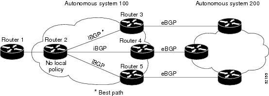
When a Border Gateway Protocol (BGP) speaking router with no local policy configured receives multiple network layer reachability information (NLRI) from the internal BGP (iBGP) for the same destination, the router will choose one iBGP path as the best path. The best path is then installed in the IP routing table of the router. For example, in Figure 1, although there are three paths to autonomous system 200, Router 2 determines that one of the paths to autonomous system 200 is the best path and uses this path only to reach autonomous system 200.
Figure 1 Non-MPLS Topology with One Best Path
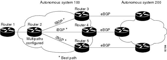
The iBGP Multipath Load Sharing feature enables the BGP speaking router to select multiple iBGP paths as the best paths to a destination. The best paths or multipaths are then installed in the IP routing table of the router. For example, on router 2 in Figure 2, the paths to routers 3, 4, and 5 are configured as multipaths and can be used to reach autonomous system 200, thereby equally sharing the load to autonomous system 200.
Figure 2 Non-MPLS Topology with Three Multipaths
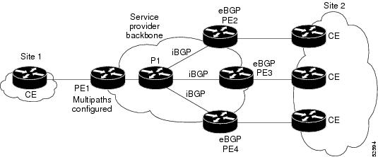
The iBGP Multipath Load Sharing feature functions similarly in a Multiprotocol Label Switching (MPLS) Virtual Private Network (VPN) with a service provider backbone. For example, on router PE1 in Figure 3, the paths to routers PE2, PE3, and PE4 can be selected as multipaths and can be used to equally share the load to site 2.
Figure 3 MPLS VPN with Three Multipaths
For multiple paths to the same destination to be considered as multipaths, the following criteria must be met:
•
•
Even if the criteria are met and multiple paths are considered multipaths, the BGP speaking router will still designate one of the multipaths as the best path and advertise this best path to its neighbors.
Benefits
Configuring multiple iBGP best paths enables a router to evenly share the traffic destined for a particular site.
Restrictions
Route Reflector Limitation
With multiple iBGP paths installed in a routing table, a route reflector will advertise only one of the paths (one next hop).
Memory Consumption Restriction
Each IP routing table entry for a BGP prefix that has multiple iBGP paths uses approximately 350 bytes of additional memory. We recommend not using this feature on a router with a low amount of available memory and especially when the router is carrying a full Internet routing table.
Related Features and Technologies
The iBGP Multipath Load Sharing feature is similar to BGP multipath support for external BGP (eBGP) paths; however, the iBGP Multipath Load Sharing feature is applied to internal rather than eBGP paths. BGP multipath support for eBGP paths is documented in the "Configuring BGP" chapter of the Cisco IOS IP Routing Configuration Guide and in the Cisco IOS IP Command Reference, Volume 2 of 3: Routing Protocols.
The iBGP Multipath Load Sharing feature is related to the BGP Link Bandwidth feature, which is documented in the "New Features in Release 12.2(14)S" area of Cisco.com.
Related Documents
For related information on this feature, refer to the following documents:
•
•
•
For more information on MPLS VPNs, refer to the following documents:
•
•
Supported Platforms
The iBGP Multipath Load Sharing feature is supported for the following platforms in Cisco IOS Release 12.2(14)S:
•
•
•
Determining Platform Support Through Cisco Feature Navigator
Cisco IOS software is packaged in feature sets that support specific platforms. To get updated information regarding platform support for this feature, access Cisco Feature Navigator. Cisco Feature Navigator dynamically updates the list of supported platforms as new platform support is added for the feature.
Cisco Feature Navigator is a web-based tool that enables you to determine which Cisco IOS software images support a specific set of features and which features are supported in a specific Cisco IOS image. You can search by feature or release. Under the release section, you can compare releases side by side to display both the features unique to each software release and the features in common.
To access Cisco Feature Navigator, you must have an account on Cisco.com. If you have forgotten or lost your account information, send a blank e-mail to cco-locksmith@cisco.com. An automatic check will verify that your e-mail address is registered with Cisco.com. If the check is successful, account details with a new random password will be e-mailed to you. Qualified users can establish an account on Cisco.com by following the directions at http://www.cisco.com/register.
Cisco Feature Navigator is updated regularly when major Cisco IOS software releases and technology releases occur. For the most current information, go to the Cisco Feature Navigator home page at the following URL:
Availability of Cisco IOS Software Images
Platform support for particular Cisco IOS software releases is dependent on the availability of the software images for those platforms. Software images for some platforms may be deferred, delayed, or changed without prior notice. For updated information about platform support and availability of software images for each Cisco IOS software release, refer to the online release notes or, if supported, Cisco Feature Navigator.
Supported Standards, MIBs, and RFCs
Standards
No new or modified standards are supported by this feature.
MIBs
No new or modified MIBs are supported by this feature.
To obtain lists of supported MIBs by platform and Cisco IOS release, and to download MIB modules, go to the Cisco MIB website on Cisco.com at the following URL:
http://www.cisco.com/public/sw-center/netmgmt/cmtk/mibs.shtml
RFCs
No new or modified RFCs are supported by this feature.
Configuration Tasks
See the following sections for configuration tasks for the iBGP Multipath Load Sharing feature. Each task in the list is identified as either required or optional.
•
•
Configuring iBGP Multipath Load Sharing
To configure the iBGP Multipath Load Sharing feature, use the following command in router configuration mode:
Router(config-router)# maximum-paths ibgp maximum-number
Controls the maximum number of parallel iBGP routes that can be installed in a routing table.
Verifying iBGP Multipath Load Sharing
To verify that the iBGP Multipath Load Sharing feature is configured correctly, perform the following steps:
Step 1
Router# show ip bgp 10.22.22.0BGP routing table entry for 10.22.22.0/24, version 119Paths:(6 available, best #1)Multipath:iBGPFlag:0x820Advertised to non peer-group peers:10.1.12.122210.2.3.8 (metric 11) from 10.1.3.4 (100.0.0.5)Origin IGP, metric 0, localpref 100, valid, internal, multipath, bestOriginator:100.0.0.5, Cluster list:100.0.0.42210.2.1.9 (metric 11) from 10.1.1.2 (100.0.0.9)Origin IGP, metric 0, localpref 100, valid, internal, multipathOriginator:100.0.0.9, Cluster list:100.0.0.22210.2.5.10 (metric 11) from 10.1.5.6 (100.0.0.10)Origin IGP, metric 0, localpref 100, valid, internal, multipathOriginator:100.0.0.10, Cluster list:100.0.0.62210.2.4.10 (metric 11) from 10.1.4.5 (100.0.0.10)Origin IGP, metric 0, localpref 100, valid, internal, multipathOriginator:100.0.0.10, Cluster list:100.0.0.52210.2.6.10 (metric 11) from 10.1.6.7 (100.0.0.10)Origin IGP, metric 0, localpref 100, valid, internal, multipathOriginator:100.0.0.10, Cluster list:100.0.0.7Router# show ip bgp vpnv4 all 10.22.22.0BGP routing table entry for 100:1:10.22.22.0/24, version 50Paths:(6 available, best #1)Multipath:iBGPAdvertised to non peer-group peers:200.1.12.122210.22.7.8 (metric 11) from 10.11.3.4 (100.0.0.8)Origin IGP, metric 0, localpref 100, valid, internal, multipath, bestExtended Community:RT:100:1Originator:100.0.0.8, Cluster list:100.1.1.442210.22.1.9 (metric 11) from 10.11.1.2 (100.0.0.9)Origin IGP, metric 0, localpref 100, valid, internal, multipathExtended Community:RT:100:1Originator:100.0.0.9, Cluster list:100.1.1.222210.22.6.10 (metric 11) from 10.11.6.7 (100.0.0.10)Origin IGP, metric 0, localpref 100, valid, internal, multipathExtended Community:RT:100:1Originator:100.0.0.10, Cluster list:100.0.0.72210.22.4.10 (metric 11) from 10.11.4.5 (100.0.0.10)Origin IGP, metric 0, localpref 100, valid, internal, multipathExtended Community:RT:100:1Originator:100.0.0.10, Cluster list:100.0.0.52210.22.5.10 (metric 11) from 10.11.5.6 (100.0.0.10)Origin IGP, metric 0, localpref 100, valid, internal, multipathExtended Community:RT:100:1Originator:100.0.0.10, Cluster list:100.0.0.6Step 2
Step 3
Router# show ip route 10.22.22.0Routing entry for 10.22.22.0/24Known via "bgp 1", distance 200, metric 0Tag 22, type internalLast update from 10.2.6.10 00:00:03 agoRouting Descriptor Blocks:* 10.2.3.8, from 10.1.3.4, 00:00:03 agoRoute metric is 0, traffic share count is 1AS Hops 110.2.1.9, from 10.1.1.2, 00:00:03 agoRoute metric is 0, traffic share count is 1AS Hops 110.2.5.10, from 10.1.5.6, 00:00:03 agoRoute metric is 0, traffic share count is 1AS Hops 110.2.4.10, from 10.1.4.5, 00:00:03 agoRoute metric is 0, traffic share count is 1AS Hops 110.2.6.10, from 10.1.6.7, 00:00:03 agoRoute metric is 0, traffic share count is 1AS Hops 1Router# show ip route vrf PATH 10.22.22.0Routing entry for 10.22.22.0/24Known via "bgp 1", distance 200, metric 0Tag 22, type internalLast update from 10.22.5.10 00:01:07 agoRouting Descriptor Blocks:* 10.22.7.8 (Default-IP-Routing-Table), from 10.11.3.4, 00:01:07 agoRoute metric is 0, traffic share count is 1AS Hops 110.22.1.9 (Default-IP-Routing-Table), from 10.11.1.2, 00:01:07 agoRoute metric is 0, traffic share count is 1AS Hops 110.22.6.10 (Default-IP-Routing-Table), from 10.11.6.7, 00:01:07 agoRoute metric is 0, traffic share count is 1AS Hops 110.22.4.10 (Default-IP-Routing-Table), from 10.11.4.5, 00:01:07 agoRoute metric is 0, traffic share count is 1AS Hops 110.22.5.10 (Default-IP-Routing-Table), from 10.11.5.6, 00:01:07 agoRoute metric is 0, traffic share count is 1AS Hops 1Step 4
Monitoring and Maintaining iBGP Multipath Load Sharing
To display iBGP Multipath Load Sharing information, use the following commands in EXEC mode, as needed:
Configuration Examples
This section provides the following configuration examples:
Both examples assume that the appropriate attributes for each path are equal and that the next hop router for each multipath is different.
Non-MPLS Topology Example
The following example shows how to set up the iBGP Multipath Load Sharing feature in a non-MPLS topology (see Figure 4).
Figure 4 Non-MPLS Topology Example
Router 2 Configuration
router bgp 100maximum-paths ibgp 3MPLS VPN Topology Example
The following example shows how to set up the iBGP Multipath Load Sharing feature in an MPLS VPN topology (see Figure 5).
Figure 5 MPLS VPN Topology Example
Router PE1 Configuration
router bgp 100address-family ipv4 unicast vrf site2maximum-paths ibgp 3Command Reference
This section documents new and modified commands. All other commands used with this feature are documented in the Cisco IOS Release 12.2 command reference publications.
New Commands
•
Modified Commands
•
•
•
•
maximum-paths ibgp
To control the maximum number of parallel internal Border Gateway Protocol (BGP) routes that can be installed in a routing table, use the maximum-paths ibgp command in router configuration mode. To restore the default value, use the no form of this command.
maximum-paths ibgp maximum-number
no maximum-paths ibgp maximum-number
Syntax Description
maximum-number
A number from 1 through 8. The maximum number of parallel routes an IP routing protocol installs in a routing table.
Defaults
The default for BGP is one path. The default for all other IP routing protocols is four paths.
Command Modes
Address- family configuration
Router configurationCommand History
Usage Guidelines
The iBGP Multipath Load Sharing feature is enabled when the following conditions are met:
•
•
•
Even if the criteria are met and multiple paths are considered multipaths, a BGP speaking router will still designate one of the multipaths as the best path and advertise this best path to its neighbors.
Examples
The following example allows a maximum of three parallel iBGP paths in a non-Multiprotocol Label Switching (MPLS) topology:
router bgp 100maximum-paths ibgp 3The following example allows a maximum of three parallel iBGP paths in an MPLS Virtual Private Network (VPN) topology:
router bgp 100address-family ipv4 unicast vrf redmaximum-paths ibgp 3Related Commands
maximum-paths
Controls the maximum number of parallel routes an IP routing protocol can support.
show ip bgp
To display entries in the Border Gateway Protocol (BGP) routing table, use the show ip bgp command in EXEC mode.
show ip bgp [ip-prefix] [network-mask] [longer-prefixes]
Syntax Description
Command Modes
EXEC
Command History
Examples
The following is sample output from the show ip bgp command in privileged EXEC mode:
Router# show ip bgpBGP table version is 5, local router ID is 10.0.33.34Status codes: s suppressed, d damped, h history, * valid, > best, i - internalOrigin codes: i - IGP, e - EGP, ? - incompleteNetwork Next Hop Metric LocPrf Weight Path*> 10.1.0.0 0.0.0.0 0 32768 ?* 10.2.0.0 10.0.33.35 10 0 35 ?*> 0.0.0.0 0 32768 ?* 10.0.0.0 10.0.33.35 10 0 35 ?*> 0.0.0.0 0 32768 ?*> 192.168.0.0/16 10.0.33.35 10 0 35 ?Table 1 describes the significant fields shown in the display.
The following is sample output from the show ip bgp command in privileged EXEC mode when you specify the longer-prefixes keyword:
Router# show ip bgp 192.168.0.0 255.255.0.0 longer-prefixesBGP table version is 1738, local router ID is 192.168.72.24Status codes: s suppressed, * valid, > best, i - internalOrigin codes: i - IGP, e - EGP, ? - incompleteNetwork Next Hop Metric LocPrf Weight Path*> 198.168.0.0 198.168.72.30 8896 32768 ?* 198.168.72.30 0 109 108 ?*> 198.168.1.0 198.168.72.30 8796 32768 ?* 198.168.72.30 0 109 108 ?*> 198.168.11.0 198.168.72.30 42482 32768 ?* 198.168.72.30 0 109 108 ?*> 198.168.14.0 198.168.72.30 8796 32768 ?* 198.168.72.30 0 109 108 ?*> 198.168.15.0 198.168.72.30 8696 32768 ?* 198.168.72.30 0 109 108 ?*> 198.168.16.0 198.168.72.30 1400 32768 ?* 198.168.72.30 0 109 108 ?*> 198.168.17.0 198.168.72.30 1400 32768 ?* 198.168.72.30 0 109 108 ?*> 198.168.18.0 198.168.72.30 8876 32768 ?* 198.168.72.30 0 109 108 ?*> 198.168.19.0 198.168.72.30 8876 32768 ?* 198.168.72.30 0 109 108 ?The following is sample output from the show ip bgp command in privileged EXEC mode that shows information including multipaths and a best path to network 10.22.22.0:
Router# show ip bgp 10.22.22.0BGP routing table entry for 10.22.22.0/24, version 119Paths:(6 available, best #1)Multipath:iBGPFlag:0x820Advertised to non peer-group peers:10.1.12.122210.2.3.8 (metric 11) from 10.1.3.4 (100.0.0.5)Origin IGP, metric 0, localpref 100, valid, internal, multipath, bestOriginator:100.0.0.5, Cluster list:100.0.0.42210.2.1.9 (metric 11) from 10.1.1.2 (100.0.0.9)Origin IGP, metric 0, localpref 100, valid, internal, multipathOriginator:100.0.0.9, Cluster list:100.0.0.22210.2.5.10 (metric 11) from 10.1.5.6 (100.0.0.10)Origin IGP, metric 0, localpref 100, valid, internal, multipathOriginator:100.0.0.10, Cluster list:100.0.0.62210.2.4.10 (metric 11) from 10.1.4.5 (100.0.0.10)Origin IGP, metric 0, localpref 100, valid, internal, multipathOriginator:100.0.0.10, Cluster list:100.0.0.52210.2.6.10 (metric 11) from 10.1.6.7 (100.0.0.10)Origin IGP, metric 0, localpref 100, valid, internal, multipathOriginator:100.0.0.10, Cluster list:100.0.0.7
Note
Table 2 describes the significant fields shown in the display.
Related Commands
clear ip bgp
Resets a BGP connection or session.
neighbor soft-reconfiguration
Configures the Cisco IOS software to start storing updates.
show ip bgp vpnv4
To display Virtual Private Network (VPN) address information from the Border Gateway Protocol (BGP) table, use the show ip bgp vpnv4 command in EXEC mode.
show ip bgp vpnv4 {all | rd route-distinguisher | vrf vrf-name} [ip-prefix/length [longer-prefixes] [output-modifiers]] [network-address [mask] [longer-prefixes] [output-modifiers]] [cidr-only] [community] [community-list] [dampened-paths] [filter-list] [flap-statistics] [inconsistent-as] [neighbors] [paths [line]] [peer-group] [quote-regexp] [regexp] [summary] [tags]
Syntax Description
Defaults
No default behavior or values.
Command Modes
EXEC
Command History
Usage Guidelines
Use this command to display VPNv4 information from the BGP database. The show ip bgp vpnv4 all command displays all available VPNv4 information. The show ip bgp vpnv4 summary command displays BGP neighbor status.
Examples
The following example shows output for all available VPNv4 information in a BGP routing table:
Router# show ip bgp vpnv4 allBGP table version is 18, local router ID is 10.14.14.14Status codes: s suppressed, d damped, h history, * valid, > best, i - internalOrigin codes: i - IGP, e - EGP,? - incompleteNetwork Next Hop Metric LocPrf Weight PathRoute Distinguisher: 100:1 (vrf1)*> 10.1.0.0 10.5.0.1 0 0 101 i*>i10.2.0.0 10.13.13.13 0 100 0 102 i*> 10.5.0.0 10.5.0.1 0 0 101 i*>i10.6.0.0 10.13.13.13 0 100 0 102 iTable 3 describes the significant fields shown in the display.
The following example shows how to display a table of labels for NLRIs that have a route distinguisher value of 100:1.
Router# show ip bgp vpnv4 rd 100:1 tagsNetwork Next Hop In tag/Out tagRoute Distinguisher: 100:1 (vrf1)10.2.0.0 10.20.0.60 34/notag10.0.0.0 10.20.0.60 35/notag10.12.0.0 10.20.0.60 26/notag10.20.0.60 26/notag10.13.0.0 10.15.0.15 notag/26Table 4 describes the significant fields shown in the display.
The following example shows VPNv4 routing entries for the VRF named vrf1:
Router# show ip bgp vpnv4 vrf vrf1BGP table version is 18, local router ID is 10.14.14.14Status codes: s suppressed, d damped, h history, * valid, > best, i - internalOrigin codes: i - IGP, e - EGP,? - incompleteNetwork Next Hop Metric LocPrf Weight PathRoute Distinguisher: 100:1 (vrf1)*> 10.11.0.0 50.0.0.1 0 0 101 i*>i10.12.0.0 13.13.13.13 0 100 0 102 i*> 10.50.0.0 50.0.0.1 0 0 101 i*>i10.51.0.0 10.13.13.13 0 100 0 102 iTable 5 describes the significant fields shown in the display.
The following example shows attributes for network 10.22.22.0 that includes multipaths and a best path:
Router# show ip bgp vpnv4 all 10.22.22.0BGP routing table entry for 100:1:10.22.22.0/24, version 50Paths:(6 available, best #1)Multipath:iBGPAdvertised to non peer-group peers:200.1.12.122210.22.7.8 (metric 11) from 10.11.3.4 (100.0.0.8)Origin IGP, metric 0, localpref 100, valid, internal, multipath, bestExtended Community:RT:100:1Originator:100.0.0.8, Cluster list:100.1.1.442210.22.1.9 (metric 11) from 10.11.1.2 (100.0.0.9)Origin IGP, metric 0, localpref 100, valid, internal, multipathExtended Community:RT:100:1Originator:100.0.0.9, Cluster list:100.1.1.222210.22.6.10 (metric 11) from 10.11.6.7 (100.0.0.10)Origin IGP, metric 0, localpref 100, valid, internal, multipathExtended Community:RT:100:1Originator:100.0.0.10, Cluster list:100.0.0.72210.22.4.10 (metric 11) from 10.11.4.5 (100.0.0.10)Origin IGP, metric 0, localpref 100, valid, internal, multipathExtended Community:RT:100:1Originator:100.0.0.10, Cluster list:100.0.0.52210.22.5.10 (metric 11) from 10.11.5.6 (100.0.0.10)Origin IGP, metric 0, localpref 100, valid, internal, multipathExtended Community:RT:100:1Originator:100.0.0.10, Cluster list:100.0.0.6Table 6 describes the significant fields shown in the display.
Related Commands
show ip route
To display the current state of the routing table, use the show ip route command in EXEC mode.
show ip route [ip-address [mask] [longer-prefixes]] | [protocol [process-id]]
Syntax Description
Command Modes
EXEC
Command History
Examples
The following is sample output from the show ip route command when entered without an address:
Router# show ip routeCodes: I - IGRP derived, R - RIP derived, O - OSPF derived,C - connected, S - static, E - EGP derived, B - BGP derived,* - candidate default route, IA - OSPF inter area route,i - IS-IS derived, ia - IS-IS, U - per-user static route,o - on-demand routing, M - mobile, P - periodic downloaded static route,D - EIGRP, EX - EIGRP external, E1 - OSPF external type 1 route,E2 - OSPF external type 2 route, N1 - OSPF NSSA external type 1 route,N2 - OSPF NSSA external type 2 routeGateway of last resort is 10.119.254.240 to network 10.140.0.0O E2 10.150.0.0 [160/5] via 10.119.254.6, 0:01:00, Ethernet2E 10.67.131.0 [200/128] via 10.119.254.244, 0:02:22, Ethernet2O E2 10.68.132.0 [160/5] via 10.119.254.6, 0:00:59, Ethernet2O E2 10.130.0.0 [160/5] via 10.119.254.6, 0:00:59, Ethernet2E 10.128.0.0 [200/128] via 10.119.254.244, 0:02:22, Ethernet2E 10.129.0.0 [200/129] via 10.119.254.240, 0:02:22, Ethernet2E 10.65.129.0 [200/128] via 10.119.254.244, 0:02:22, Ethernet2E 10.131.0.0 [200/128] via 10.119.254.244, 0:02:22, Ethernet2E 10.75.139.0 [200/129] via 10.119.254.240, 0:02:23, Ethernet2E 10.16.208.0 [200/128] via 10.119.254.244, 0:02:22, Ethernet2E 10.84.148.0 [200/129] via 10.119.254.240, 0:02:23, Ethernet2E 10.31.223.0 [200/128] via 10.119.254.244, 0:02:22, Ethernet2E 10.44.236.0 [200/129] via 10.119.254.240, 0:02:23, Ethernet2E 10.141.0.0 [200/129] via 10.119.254.240, 0:02:22, Ethernet2E 10.140.0.0 [200/129] via 10.119.254.240, 0:02:23, Ethernet2The following is sample output that includes IS-IS Level 2 routes learned:
Router# show ip routeCodes: I - IGRP derived, R - RIP derived, O - OSPF derived,C - connected, S - static, E - EGP derived, B - BGP derived,* - candidate default route, IA - OSPF inter area route,i - IS-IS derived, ia - IS-IS, U - per-user static route,o - on-demand routing, M - mobile, P - periodic downloaded static route,D - EIGRP, EX - EIGRP external, E1 - OSPF external type 1 route,E2 - OSPF external type 2 route, N1 - OSPF NSSA external type 1 route,N2 - OSPF NSSA external type 2 routeGateway of last resort is not set10.89.0.0 is subnetted (mask is 255.255.255.0), 3 subnetsC 10.89.64.0 255.255.255.0 is possibly down,routing via 0.0.0.0, Ethernet0i L2 10.89.67.0 [115/20] via 10.89.64.240, 0:00:12, Ethernet0i L2 10.89.66.0 [115/20] via 10.89.64.240, 0:00:12, Ethernet0Table 7 describes the significant fields shown in the displays.
When you specify that you want information about a specific network displayed, more detailed statistics are shown. The following is sample output from the show ip route command when entered with the address 10.0.0.1:
Router# show ip route 10.0.0.1Routing entry for 10.0.0.1/32Known via "isis", distance 115, metric 20, type level-1Redistributing via isisLast update from 10.191.255.251 on Fddi1/0, 00:00:13 agoRouting Descriptor Blocks:* 10.22.22.2, from 10.191.255.247, via Serial2/3Route metric is 20, traffic share count is 110.191.255.251, from 10.191.255.247, via Fddi1/0Route metric is 20, traffic share count is 1When an IS-IS router advertises its link-state information, it includes one of its own IP addresses to be used as the originator IP address. When other routers calculate IP routes, they can store the originator IP address with each route in the routing table.
The following example shows the output from the show ip route command when looking at an IP route generated by IS-IS. Each path that is shown under the Routing Descriptor Blocks report displays two IP addresses. The first address (10.22.22.2) is the next hop address. The second is the originator IP address from the advertising IS-IS router. This address helps you determine where a particular IP route has originated in your network. In the example the route to 10.0.0.1/32 was originated by a router with IP address 10.191.255.247.
Router# show ip route 10.0.0.1Routing entry for 10.0.0.1/32Known via "isis", distance 115, metric 20, type level-1Redistributing via isisLast update from 10.191.255.251 on Fddi1/0, 00:00:13 agoRouting Descriptor Blocks:* 10.22.22.2, from 10.191.255.247, via Serial2/3Route metric is 20, traffic share count is 110.191.255.251, from 10.191.255.247, via Fddi1/0Route metric is 20, traffic share count is 1Table 8 describes the significant fields shown when using the show ip route command with an IP address (previous displays).
The following is sample output using the longer-prefixes keyword. When the longer-prefixes keyword is included, the address and mask pair becomes the prefix, and any address that matches that prefix is displayed. Therefore, multiple addresses are displayed.
In the following example, the logical AND operation is performed on the source address 10.0.0.0 and the mask 10.0.0.0, resulting in 10.0.0.0. Each destination in the routing table is also logically ANDed with the mask and compared to that result of 10.0.0.0. Any destinations that fall into that range are displayed in the output.
Router# show ip route 10.0.0.0 10.0.0.0 longer-prefixesCodes: I - IGRP derived, R - RIP derived, O - OSPF derived,C - connected, S - static, E - EGP derived, B - BGP derived,* - candidate default route, IA - OSPF inter area route,i - IS-IS derived, ia - IS-IS, U - per-user static route,o - on-demand routing, M - mobile, P - periodic downloaded static route,D - EIGRP, EX - EIGRP external, E1 - OSPF external type 1 route,E2 - OSPF external type 2 route, N1 - OSPF NSSA external type 1 route,N2 - OSPF NSSA external type 2 routeGateway of last resort is not setS 10.134.0.0 is directly connected, Ethernet0S 10.131.0.0 is directly connected, Ethernet0S 10.129.0.0 is directly connected, Ethernet0S 10.128.0.0 is directly connected, Ethernet0S 10.49.246.0 is directly connected, Ethernet0S 10.160.97.0 is directly connected, Ethernet0S 10.153.88.0 is directly connected, Ethernet0S 10.76.141.0 is directly connected, Ethernet0S 10.75.138.0 is directly connected, Ethernet0S 10.44.237.0 is directly connected, Ethernet0S 10.31.222.0 is directly connected, Ethernet0S 10.16.209.0 is directly connected, Ethernet0S 10.145.0.0 is directly connected, Ethernet0S 10.141.0.0 is directly connected, Ethernet0S 10.138.0.0 is directly connected, Ethernet0S 10.128.0.0 is directly connected, Ethernet010.19.0.0 255.255.255.0 is subnetted, 1 subnetsC 10.19.64.0 is directly connected, Ethernet010.69.0.0 is variably subnetted, 2 subnets, 2 masksC 10.69.232.32 255.255.255.240 is directly connected, Ethernet0S 10.69.0.0 255.255.0.0 is directly connected, Ethernet0Related Commands
show interfaces tunnel
Displays a list of tunnel interface information.
show ip route summary
Displays the current state of the routing table in summary format.
show ip route vrf
To display the IP routing table associated with a VPN routing and forwarding instance (VRF), use the show ip route vrf command in EXEC mode.
show ip route vrf vrf-name [connected] [protocol [as-number] [tag] [output-modifiers]] [ip-prefix] [list number [output-modifiers]] [profile] [static [output-modifiers]] [summary [output-modifiers]] [supernets-only [output-modifiers]]
Syntax Description
Defaults
No default behavior or values.
Command Modes
EXEC
Command History
Usage Guidelines
This command displays specified information from the IP routing table of a VRF.
Examples
This example shows the IP routing table associated with the VRF called vrf1:
Router# show ip route vrf vrf1Codes: C - connected, S - static, I - IGRP, R - RIP, M - mobile, B - BGPD - EIGRP, EX - EIGRP external, O - OSPF, IA - OSPF inter areaN1 - OSPF NSSA external type 1, N2 - OSPF NSSA external type 2E1 - OSPF external type 1, E2 - OSPF external type 2, E - EGPi - IS-IS, L1 - IS-IS level-1, L2 - IS-IS level-2, * - candidate defaultU - per-user static route, o - ODRT - traffic engineered routeGateway of last resort is not setB 51.0.0.0/8 [200/0] via 13.13.13.13, 00:24:19C 50.0.0.0/8 is directly connected, Ethernet1/3B 11.0.0.0/8 [20/0] via 50.0.0.1, 02:10:22B 12.0.0.0/8 [200/0] via 13.13.13.13, 00:24:20This example shows BGP entries in the IP routing table associated with the VRF named vrf1:
Router# show ip route vrf vrf1 bgpB 51.0.0.0/8 [200/0] via 13.13.13.13, 03:44:14B 11.0.0.0/8 [20/0] via 51.0.0.1, 03:44:12B 12.0.0.0/8 [200/0] via 13.13.13.13, 03:43:14This example shows the IP routing table associated with a VRF named PATH and network 10.22.22.0: Router# show ip route vrf PATH 10.22.22.0
Routing entry for 10.22.22.0/24Known via "bgp 1", distance 200, metric 0Tag 22, type internalLast update from 10.22.5.10 00:01:07 agoRouting Descriptor Blocks:* 1.22.7.8 (Default-IP-Routing-Table), from 1.11.3.4, 00:01:07 agoRoute metric is 0, traffic share count is 1AS Hops 11.22.1.9 (Default-IP-Routing-Table), from 1.11.1.2, 00:01:07 agoRoute metric is 0, traffic share count is 1AS Hops 11.22.6.10 (Default-IP-Routing-Table), from 1.11.6.7, 00:01:07 agoRoute metric is 0, traffic share count is 1AS Hops 11.22.4.10 (Default-IP-Routing-Table), from 1.11.4.5, 00:01:07 agoRoute metric is 0, traffic share count is 1AS Hops 11.22.5.10 (Default-IP-Routing-Table), from 1.11.5.6, 00:01:07 agoRoute metric is 0, traffic share count is 1AS Hops 1Table 9 describes the significant fields shown when using the show ip route vrf vrf-name ip-prefix command.
Related Commands
show ip cache
Displays the CEF forwarding table associated with a VRF.
show ip vrf
Displays the set of defined VRFs and associated interfaces.