Feedback Feedback
|
Table Of Contents
MPLS Traffic Engineering - DiffServ Aware (DS-TE)
Related Features and Technologies
Platforms and Interfaces Supported
The tunnel mpls traffic-eng bandwidth command
Level 1: Configuring the Device
Level 2: Configuring the Physical Interface
Level 3: Configuring the Tunnel Interface
Guaranteed Bandwidth Service Configuration
Guaranteed Bandwidth Service Examples
Example with Single Destination Prefix
Tunnel Midpoint Configuration [Mid-1]
Tunnel Midpoint Configuration [Mid-2]
Example with Many Destination Prefixes
Configuration of Tunnel Head-1
Configuration of Tunnel Head-2
Tunnel Midpoint Configuration [Mid-1]
Tunnel Midpoint Configuration [Mid-2]
mpls traffic-eng administrative-weight
mpls traffic-eng attribute-flags
mpls traffic-eng backup-path tunnel
mpls traffic-eng flooding thresholds
mpls traffic-eng link timers bandwidth-hold
mpls traffic-eng link timers periodic-flooding
mpls traffic-eng reoptimize timers frequency
show mpls traffic-eng autoroute
show mpls traffic-eng fast-reroute database
show mpls traffic-eng fast-reroute log reroutes
show mpls traffic-eng link-management admission-control
show mpls traffic-eng link-management advertisements
show mpls traffic-eng link-management bandwidth-allocation
show mpls traffic-eng link-management igp-neighbors
show mpls traffic-eng link-management interfaces
show mpls traffic-eng link-management summary
show mpls traffic-eng topology
tunnel mpls traffic-eng affinity
tunnel mpls traffic-eng autoroute announce
tunnel mpls traffic-eng autoroute metric
tunnel mpls traffic-eng bandwidth
tunnel mpls traffic-eng fast-reroute
tunnel mpls traffic-eng path-option
tunnel mpls traffic-eng priority
debug mpls traffic-eng link-management preemption
MPLS Traffic Engineering - DiffServ Aware (DS-TE)
This guide presents extensions made to Multiprotocol Label Switching Traffic Engineering (MPLS TE) that make it DiffServ aware. Specifically, the bandwidth reservable on each link for constraint-based routing (CBR) purposes can now be managed through two bandwidth pools: a global pool and a sub-pool. The sub-pool can be limited to a smaller portion of the link bandwidth. Tunnels using the sub-pool bandwidth can then be used in conjunction with MPLS Quality of Service (QoS) mechanisms to deliver guaranteed bandwidth services end-to-end across the network.
Feature History
The guide contains the following sections:
•
Background and Overview, page 2
•
•
Note
Background and Overview
MPLS traffic engineering allows constraint-based routing of IP traffic. One of the constraints satisfied by CBR is the availability of required bandwidth over a selected path. DiffServ-aware Traffic Engineering extends MPLS traffic engineering to enable you to perform constraint-based routing of "guaranteed" traffic, which satisfies a more restrictive bandwidth constraint than that satisfied by CBR for regular traffic. The more restrictive bandwidth is termed a sub-pool, while the regular TE tunnel bandwidth is called the global pool. (The sub-pool is a portion of the global pool.) This ability to satisfy a more restrictive bandwidth constraint translates into an ability to achieve higher Quality of Service performance (in terms of delay, jitter, or loss) for the guaranteed traffic.
For example, DS-TE can be used to ensure that traffic is routed over the network so that, on every link, there is never more than 40 per cent (or any assigned percentage) of the link capacity of guaranteed traffic (for example, voice), while there can be up to 100 per cent of the link capacity of regular traffic. Assuming QoS mechanisms are also used on every link to queue guaranteed traffic separately from regular traffic, it then becomes possible to enforce separate "overbooking" ratios for guaranteed and regular traffic. (In fact, for the guaranteed traffic it becomes possible to enforce no overbooking at all—or even an underbooking—so that very high QoS can be achieved end-to-end for that traffic, even while for the regular traffic a significant overbooking continues to be enforced.)
Also, through the ability to enforce a maximum percentage of guaranteed traffic on any link, the network administrator can directly control the end-to-end QoS performance parameters without having to rely on over-engineering or on expected shortest path routing behavior. This is essential for transport of applications that have very high QoS requirements (such as real-time voice, virtual IP leased line, and bandwidth trading), where over-engineering cannot be assumed everywhere in the network.
DS-TE involves extending OSPF (Open Shortest Path First routing protocol), so that the available sub-pool bandwidth at each preemption level is advertised in addition to the available global pool bandwidth at each preemption level. And DS-TE modifies constraint-based routing to take this more complex advertised information into account during path computation.
Benefits
DiffServ-aware Traffic Engineering enables service providers to perform separate admission control and separate route computation for discrete subsets of traffic (for example, voice and data traffic).
Therefore, by combining DS-TE with other IOS features such as QoS, the service provider can:
•
•
•
•
Related Features and Technologies
The DS-TE feature is related to OSPF, IS-IS, RSVP (Resource reSerVation Protocol), QoS, and MPLS traffic engineering. Cisco documentation for all of these features is listed in the next section.
Related Documents
For OSPF:
•
http://www.cisco.com/univercd/cc/td/doc/product/software/ios121/121cgcr/ip_c/ipcprt2/1cdospf.htm•
For IS-IS:
•
•
http://www.cisco.com/univercd/cc/td/doc/product/software/ios121/121cgcr/ip_r/iprprt2/1rdisis.htmFor RSVP:
•
http://www.cisco.com/univercd/cc/td/doc/product/software/ios121/121cgcr/qos_c/qcprt5/qcdrsvp.htm•
For QoS:
•
http://www.cisco.com/univercd/cc/td/doc/product/software/ios121/121cgcr/qos_c/index.htm•
http://www.cisco.com/univercd/cc/td/doc/product/software/ios121/121cgcr/qos_r/index.htmFor MPLS Traffic Engineering:
•
http://www.cisco.com/univercd/cc/td/doc/product/software/ios121/121newft/121t/121t3/traffeng.htm•
http://www.cisco.com/univercd/cc/td/doc/product/software/ios121/121cgcr/switch_c/xcprt4•
http://www.cisco.com/univercd/cc/td/doc/product/software/ios121/121cgcr/switch_r/xrdscmd3.htmPlatforms and Interfaces Supported
This release supports DS-TE together with QoS on the 7500 Series Router (VIP) over the POS (Packet over Sonet) interface.
To check for changes in platform support since the publication of this document, access Feature Navigator at http://www.cisco.com/go/fn . You must have an account on Cisco.com . Qualified users can establish an account by following directions at http://www.cisco.com/register.
If you have forgotten or lost your account information, send a blank e-mail to cco-locksmith@cisco.com. An automatic check will verify that your e-mail address is registered, and account details with a new random password will then be e-mailed to you.
Supported Standards
Standardization of DiffServ-aware MPLS Traffic Engineering is still in progress in the IETF (Internet Engineering Task Force). At the time of publication of this feature guide, DS-TE has been documented in the following IETF drafts:
•
http://search.ietf.org/internet-drafts/draft-ietf-tewg-diff-te-reqts-05.txt•
http://search.ietf.org/internet-drafts/draft-ietf-tewg-diff-te-proto-01.txtAs the IETF work is still in progress, details are still under definition and subject to change, so DS-TE should be considered as a pre-standard implementation of IETF Diff-Serv-aware MPLS Traffic Engineering. However, it is in line with the requirements described in the first document above. The concept of "Class-Type" defined in that IETF draft corresponds to the concept of bandwidth pool implemented by DS-TE. And because DS-TE supports two bandwidth pools (global pool and sub-pool), DS-TE should be seen as supporting two Class-Types (Class-Type 0 and Class-Type 1).
Prerequisites
Your network must support the following Cisco IOS features in order to support guaranteed bandwidth services based on DiffServ-aware Traffic Engineering:
•
•
•
•
•
Configuration Tasks
This section lists the minimum set of commands you need to implement the DiffServ-aware Traffic Engineering feature—in other words, to establish a tunnel that reserves bandwidth from the sub-pool.
The subsequent "Configuration Examples" section (page 10), presents these same commands in context and shows how, by combining them with QoS commands, you can build guaranteed bandwidth services.
New Commands
DS-TE commands were developed from the existing command set that configures MPLS traffic engineering. The only difference introduced to create DS-TE was the expansion of two commands:
•
•
The ip rsvp bandwidth command
The old command was
ip rsvp bandwidth x ywhere x = the size of the only possible pool, and y = the size of a single traffic flow (ignored by traffic engineering)
Now the extended command is
ip rsvp bandwidth x y sub-pool zwhere x = the size of the global pool, and z = the size of the sub-pool.
(Remember, the sub-pool's bandwidth is less than—because it is part of—the global pool's bandwidth.)
The tunnel mpls traffic-eng bandwidth command
The old command was
tunnel mpls traffic-eng bandwidth bwhere b = the amount of bandwidth this tunnel requires.
Now you specify from which pool (global or sub) the tunnel's bandwidth is to come. You can enter
tunnel mpls traffic-eng bandwidth sub-pool bThis indicates that the tunnel should use bandwidth from the sub-pool. Alternatively, you can enter
tunnel mpls traffic-eng bandwidth bThis indicates that the tunnel should use bandwidth from the global pool (the default).
The Configuration Procedure
To establish a sub-pool TE tunnel, you must enter configurations at three levels:
•
•
•
On the first two levels, you activate traffic engineering; on the third level—the tunnel interface—you establish the sub-pool tunnel. Therefore, it is only at the tunnel headend device that you need to configure all three levels. At the tunnel midpoints and tail, it is sufficient to configure the first two levels.
In the tables below, each command is explained in brief. For a more complete explanation of any command, refer to the page given in the right-hand column.
Level 1: Configuring the Device
At this level, you tell the device (router or switch router) to use accelerated packet-forwarding (known as Cisco Express Forwarding or CEF), MultiProtocol Label Switching (MPLS), traffic-engineering tunneling, and either the OSPF or IS-IS routing algorithm (Open Shortest Path First or Intermediate System to Intermediate System). This level is often called global configuration mode because the configuration is applied globally, to the entire device, rather than to a specific interface or routing instance. (These commands have not been modified from earlier releases of Cisco IOS.)
You enter the following commands:
Step 1
Enables CEF—which accelerates the flow of packets through the device. (More on page 42.)
Step 2
Enables MPLS, and specifically its traffic engineering tunnel capability. (More on page 61.)
Step 3
Invokes the OSPF routing process for IP and puts the device into router configuration mode. (More on page 68.) Proceed now to Steps 9 and 10.
Alternatively, you may invoke the ISIS routing process with this command (more on page 66), and continue with Step 4.
Step 4
Specifies the IS-IS network entity title (NET) for the routing process. (More on page 63.)
Step 5
Enables the router to generate and accept IS-IS new-style TLVs (type, length, and value objects). (More on page 48.)
Step 6
Configures the router to learn about destinations inside its own area or "IS-IS level". (More on page 47.)
Step 7
Specifies the IS-IS level (which must be same level as in the preceding step) to which the router will flood MPLS traffic- engineering link information. (More on page 50).
Step 8
Instructs IS-IS to advertise the IP address of the loopback interface without actually running IS-IS on that interface. (More on page 64.) Continue with Step 9 but don't do Step 10—because Step 10 refers to OSPF.
Step 9
Specifies that the traffic engineering router identifier is the IP address associated with the loopback0 interface. (More on page 60.)
Step 10
Turns on MPLS traffic engineering for a particular OSPF area. (More on page 52.)
Level 2: Configuring the Physical Interface
Having configured the device, you now must configure the interface on that device through which the tunnel will run. To do that, you first put the router into interface-configuration mode.
You then enable Resource Reservation Protocol. RSVP is used to signal (set up) a traffic engineering tunnel, and to tell devices along the tunnel path to reserve a specific amount of bandwidth for the traffic that will flow through that tunnel. It is with this command that you establish the maximum size of the sub-pool.
Finally, you enable the MPLS traffic engineering tunnel feature on this physical interface—and if you will be relying on the IS-IS routing protocol, you enable that as well.
To accomplish these tasks, you enter the following commands:
Step 1
Router(config)# interface interface-id
Moves configuration to the interface level, directing subsequent configuration commands to the specific interface identified by the interface-id. (More on page 38.)
Step 2
Router(config-if)# ip rsvp bandwidth interface-kbps sub-pool kbps
Enables RSVP on this interface and limits the amount of bandwidth RSVP can reserve on this interface. The sum of bandwidth used by all tunnels on this interface cannot exceed interface-kbps, and the sum of bandwidth used by all sub-pool tunnels cannot exceed sub-pool kbps. (More on page 45.)
Step 3
Enables the MPLS traffic engineering tunnel feature on this interface. (More on page 62.)
Step 4
Enables the IS-IS routing protocol on this interface. (More on page 44.) Do not enter this command if you are configuring for OSPF.
Level 3: Configuring the Tunnel Interface
Now you create a set of attributes for the tunnel itself; those attributes are configured on the "tunnel interface" (not to be confused with the physical interface just configured above).
The only command which was modified at this level for DS-TE is tunnel mpls traffic-eng bandwidth (described in detail on page 117).
You enter the following commands:
Step 1
Creates a tunnel interface (named in this example tunnel1) and enters interface configuration mode. (More on page 38.)
Step 2
Specifies the IP address of the tunnel tail device. (More on page 111.)
Step 3
Sets the tunnel's encapsulation mode to MPLS traffic engineering. (More on page 113.)
Step 4
Configures the tunnel's bandwidth and assigns it either to the sub-pool or the global pool. (More on page 117).
Step 5
Sets the priority to be used when system determines which existing tunnels are eligible to be preempted. (More on page 121).
Step 6
Configures the paths (hops) a tunnel should use. The user can enter an explicit path (can specify the IP addresses of the hops) or can specify a dynamic path (the router figures out the best set of hops). (More on page 119).
Verifying the Configurations
To view the complete configuration you have entered, use the EXEC command show running-config and check its output display for correctness.
To check just one tunnel's configuration, enter show interfaces tunnel followed by the tunnel interface number. And to see that tunnel's RSVP bandwidth and flow, enter show ip rsvp interface followed by the name or number of the physical interface.
Here is an example of the information displayed by these two commands. To see an explanation of each field used in the following displays turn to page 69 for show interfaces tunnel and page 83 for show ip rsvp interface.
GSR1#show interfaces tunnel 4Tunnel4 is up, line protocol is downHardware is Routing TunnelMTU 1500 bytes, BW 9 Kbit, DLY 500000 usec, rely 255/255, load 1/255Encapsulation TUNNEL, loopback not set, keepalive set (10 sec)Tunnel source 0.0.0.0, destination 0.0.0.0Tunnel protocol/transport GRE/IP, key disabled, sequencing disabledLast input never, output never, output hang neverLast clearing of "show interface" counters neverOutput queue 0/0, 0 drops; input queue 0/75, 0 dropsFive minute input rate 0 bits/sec, 0 packets/secFive minute output rate 0 bits/sec, 0 packets/sec0 packets input, 0 bytes, 0 no bufferReceived 0 broadcasts, 0 runts, 0 giants0 input errors, 0 CRC, 0 frame, 0 overrun, 0 ignored, 0 abort0 packets output, 0 bytes, 0 underruns0 output errors, 0 collisions, 0 interface resets, 0 restartsGSR1#show ip rsvp interface pos4/0interface allocated i/f max flow max sub maxPO4/0 300K 466500K 466500K 0MTo view all tunnels at once on the router you have configured, enter show mpls traffic-eng tunnels brief. The information displayed when tunnels are functioning properly looks like this (a table explaining the display fields begins on page 109):
GSR1#show mpls traffic-eng tunnels briefSignalling Summary:LSP Tunnels Process: runningRSVP Process: runningForwarding: enabledPeriodic reoptimization: every 3600 seconds, next in 3029 secondsTUNNEL NAME DESTINATION UP IF DOWN IF STATE/PROTGSR1_t0 192.168.1.13 - SR3/0 up/upGSR1_t1 192.168.1.13 - SR3/0 up/upGSR1_t2 192.168.1.13 - PO4/0 up/upDisplayed 3 (of 3) heads, 0 (of 0) midpoints, 0 (of 0) tailsWhen one or more tunnels is not functioning properly, the display could instead look like this. (In the following example, tunnels t0 and t1 are down, as indicated in the far right column).
GSR1#show mpls traffic-eng tunnels briefSignalling Summary:LSP Tunnels Process: runningRSVP Process: runningForwarding: enabledPeriodic reoptimization: every 3600 seconds, next in 2279 secondsTUNNEL NAME DESTINATION UP IF DOWN IF STATE/PROTGSR1_t0 192.168.1.13 - SR3/0 up/downGSR1_t1 192.168.1.13 - SR3/0 up/downGSR1_t2 192.168.1.13 - PO4/0 up/upDisplayed 3 (of 3) heads, 0 (of 0) midpoints, 0 (of 0) tailsTo find out why a tunnel is down, insert its name into this same command, after adding the keyword name and omitting the keyword brief. For example:
GSR1#show mpls traffic-eng tunnels name GSR1_t0Name:GSR1_t0 (Tunnel0) Destination:192.168.1.13Status:Admin:up Oper:down Path: not valid Signalling:connectedIf, as in this example, the Path is displayed as not valid, use the show mpls traffic-eng topology command to make sure the router has received the needed updates. (That command is described on page 106.)
Additionally, you can use any of the following show commands to inspect particular aspects of the network, router, or interface concerned:
Network
Advertised bandwidth allocation information
show mpls traffic-eng link-management advertisements (described on page 94)
Preemptions along the tunnel path
debug mpls traffic-eng link-management preemption (described on page 124)
Available TE link band- width on all head routers
show mpls traffic-eng topology (described on page 106)
Router
Status of all tunnels cur- rently signalled by this router
show mpls traffic-eng link-management admission-control (described on page 92)
Tunnels configured on midpoint routers
show mpls traffic-eng link-management summary
(described on page 104)Interface
Detailed information on current bandwidth pools
show mpls traffic-eng link-management bandwidth-allocation [interface-name]
(described on page 97)TE RSVP bookkeeping
show mpls traffic-eng link-management interfaces
(described on page 102Entire configuration of one interface
show run interface
Configuration Examples
First this section presents the DS-TE configurations needed to create the sub-pool tunnel. Then it presents the more comprehensive design for building end-to-end guaranteed bandwidth service, which involves configuring Quality of Service as well.
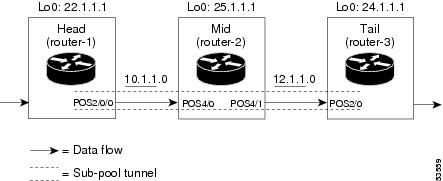
As shown in Figure 1, the tunnel configuration involves at least three devices—tunnel head, midpoint, and tail. On each of those devices one or two network interfaces must be configured, for traffic ingress and egress.
Figure 1 Sample Tunnel Topology
Tunnel Head
At the device level:
router-1# configure terminalEnter configuration commands, one per line. End with CNTL/Z.router-1(config)# ip cef distributedrouter-1(config)# mpls traffic-eng tunnels[now one uses either the IS-IS commands on the left or the OSPF commands on the right]
:
router-1(config-router)# mpls traffic-eng router-id Loopback0router-1(config-router)# exit[now one resumes the common command set]router-1(config)# interface Loopback0At the virtual interface level:
router-1(config-if)# ip address 22.1.1.1 255.255.255.255router-1(config-if)# no ip directed-broadcastrouter-1(config-if)# exitAt the device level:
router-1(config)# interface POS2/0/0At the physical interface level (egress):
router-1(config-if)# ip address 10.1.1.1 255.255.255.0router-1(config-if)# mpls traffic-eng tunnelsrouter-1(config-if)# ip rsvp bandwidth 130000 130000 sub-pool 80000[and if using IS-IS instead of OSPF]:router-1(config-if)# ip router isis[and in all cases]:router-1(config-if)# exitAt the device level:
router-1(config)# interface Tunnel1At the tunnel interface level:
router-1(config-if)# bandwidth 110000router-1(config-if)# ip unnumbered Loopback0router-1(config-if)# tunnel destination 24.1.1.1router-1(config-if)# tunnel mode mpls traffic-engrouter-1(config-if)# tunnel mpls traffic-eng priority 0 0router-1(config-if)# tunnel mpls traffic-eng bandwidth sub-pool 30000router-1(config-if)# tunnel mpls traffic-eng path-option 1 dynamicrouter-1(config-if)# exitrouter-1(config)#Midpoint Devices
At the device level:
router-2# configure terminalrouter-2(config)# ip cef distributedrouter-2(config)# mpls traffic-eng tunnels[now one uses either the IS-IS commands on the left or the OSPF commands on the right]
:
router-2(config-router)# mpls traffic-eng router-id Loopback0router-2(config-router)# exit[now one resumes the common command set]router-2(config)# interface Loopback0At the virtual interface level:
router-2(config-if)# ip address 25.1.1.1 255.255.255.255router-2(config-if)# no ip directed-broadcastrouter-2(config-if)# exitAt the device level: router-1(config)# interface POS4/0router-1(config-if)# ip address 11.1.1.2 255.255.255.0router-1(config-if)# mpls traffic-eng tunnelsrouter-1(config-if)# ip rsvp bandwidth 130000 130000 sub-pool 80000[If using IS-IS instead of OSPF]:
router-1(config-if)# ip router isis[and in all cases]:router-1(config-if)# exitAt the device level: router-1(config)# interface POS4/1router-1(config-if)# ip address 12.1.1.2 255.255.255.0router-1(config-if)# mpls traffic-eng tunnelsrouter-1(config-if)# ip rsvp bandwidth 130000 130000 sub-pool 80000[If using IS-IS instead of OSPF]:
router-1(config-if)# ip router isis[and in all cases]:router-1(config-if)# exitNote that there is no configuring of tunnel interfaces at the mid-point devices, only network interfaces and the device globally.
Tail-End Device
At the device level:
router-3# configure terminalrouter-3(config)# ip cef distributedrouter-3(config)# mpls traffic-eng tunnels[now one uses either the IS-IS commands on the left or the OSPF commands on the right]
:
router-3(config-router)# mpls traffic-eng router-id Loopback0router-3(config-router)# exit[now one resumes the common command set]router-3(config)# interface Loopback0At the virtual interface level:
router-3(config-if)# ip address 24.1.1.1 255.255.255.255router-3(config-if)# no ip directed-broadcast[and if using IS-IS instead of OSPF]:router-3(config-if)# ip router isis[and in all cases]:router-3(config-if)# exitAt the device level: router-1(config)# interface POS4/0router-1(config-if)# ip address 12.1.1.3 255.255.255.0router-1(config-if)# mpls traffic-eng tunnelsrouter-1(config-if)# ip rsvp bandwidth 130000 130000 sub-pool 80000[If using IS-IS instead of OSPF]:
router-1(config-if)# ip router isis[and in all cases]:router-1(config-if)# exit
Guaranteed Bandwidth Service Configuration
Having configured two bandwidth pools, you now can
•
•
Having a separate pool for traffic requiring strict guarantees allows you to limit the amount of such traffic admitted on any given link. Often, it is possible to achieve strict QoS guarantees only if the amount of guaranteed traffic is limited to a portion of the total link bandwidth.
Having a separate pool for other traffic (best-effort or diffserv traffic) allows you to have a separate limit for the amount of such traffic admitted on any given link. This is useful because it allows you to fill up links with best-effort/diffserv traffic, thereby achieving a greater utilization of those links.
Providing Strict QoS Guarantees Using DS-TE Sub-pool Tunnels
A tunnel using sub-pool bandwidth can satisfy the stricter requirements if you do all of the following:
1.
If delay/jitter guarantees are sought, the diffserv Expedited Forwarding queue (EF PHB) is used. On the Cisco 7500(VIP) it is the "priority" queue. You must configure the bandwidth of the queue to be at least equal to the bandwidth of the sub-pool.
If only bandwidth guarantees are sought, the diffserv Assured Forwarding PHB (AF PHB) is used. On the Cisco 7500 (VIP) you use one of the existing Class-Based Weighted Fair Queuing (CBWFQ) queues.
2.
You do this by marking the traffic that enters the tunnel with a unique value in the mpls exp bits field, and steering only traffic with that marking into the GB queue.
3.
You do this by rate-limiting the guaranteed traffic before it enters the sub-pool tunnel. The aggregate rate of all traffic entering the sub-pool tunnel should be less than or equal to the bandwidth capacity of the sub-pool tunnel. Excess traffic can be dropped (in the case of delay/jitter guarantees) or can be marked differently for preferential discard (in the case of bandwidth guarantees).
4.
You do this by setting the sub-pool bandwidth of each outbound link to the appropriate percentage of the total link bandwidth (that is, by adjusting the z parameter of the ip rsvp bandwidth command).
Providing Differentiated Service Using DS-TE Global Pool Tunnels
You can configure a tunnel using global pool bandwidth to carry best-effort as well as several other classes of traffic. Traffic from each class can receive differentiated service if you do all of the following:
1.
2.
3.
To control the amount of diffserv tunnel traffic you intend to support on a given link, adjust the size of the global pool on that link.
Providing Strict Guarantees and Differentiated Service in the Same Network
Because DS-TE allows simultaneous constraint-based routing of sub-pool and global pool tunnels, strict guarantees and diffserv can be supported simultaneously in a given network.
Guaranteed Bandwidth Service Examples
Given the many topologies in which Guaranteed Bandwidth Services can be applied, there is space here only to present two examples. They illustrate opposite ends of the spectrum of possibilities.
In the first example, the guaranteed bandwidth tunnel can be easily specified by its destination. So the forwarding criteria refer to a single destination prefix.
In the second example, there can be many final destinations for the guaranteed bandwidth traffic, including a dynamically changing number of destination prefixes. So the forwarding criteria are specified by Border Gateway Protocol (BGP) policies.
Example with Single Destination Prefix
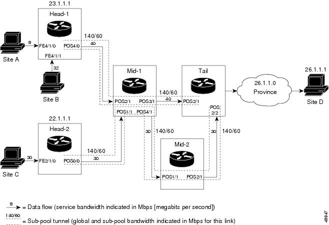
Figure 2 illustrates a topology for guaranteed bandwidth services whose destination is specified by a single prefix, either Site D (like a voice gateway, here bearing prefix 26.1.1.1) or a subnet (like the location of a web farm, here called "Province" and bearing prefix 26.1.1.0). Three services are offered:
•
•
•
Figure 2 Sample Topology for Guaranteed Bandwidth Services to a Single Destination Prefix
These three services run through two sub-pool tunnels:
•
•
Both tunnels use the same tail router, though they have different heads. (In Figure 2 one midpoint router is shared by both tunnels. In the real world there could of course be many more midpoints.)
All POS interfaces in this example are OC3, whose capacity is 155 Mbps.
Configuring Tunnel Head-1
First we recapitulate commands that establish two bandwidth pools and a sub-pool tunnel (as presented earlier in this Configuration Examples section). Then we present the QoS commands that guarantee end-to-end service on the subpool tunnel. (With the 7500 router, Modular QoS CLI is used.)
Configuring the Pools and Tunnel
At the device level:
router-1(config)# ip cef distributedrouter-1(config)# mpls traffic-eng tunnels[now one uses either the IS-IS commands on the left or the OSPF commands on the right]
:
router-1(config-router)# mpls traffic-eng router-id Loopback0router-1(config-router)# exit[now one resumes the common command set]Create a virtual interface:
router-1(config)# interface Loopback0router-1(config-if)# ip address 23.1.1.1 255.255.255.255router-1(config-if)# no ip directed-broadcastrouter-1(config-if)# exitAt the outgoing physical interface:
router-1(config)# interface pos4/0router-1(config-if)# ip address 10.1.1.1 255.0.0.0router-1(config-if)# mpls traffic-eng tunnelsrouter-1(config-if)# ip rsvp bandwidth 140000 140000 sub-pool 60000[and if using IS-IS instead of OSPF]:router-1(config-if)# ip router isis[and in all cases}:router-1(config-if)# exitAt the tunnel interface:
router-1(config)# interface Tunnel1router-1(config-if)# bandwidth 110000router-1(config-if)# ip unnumbered Loopback0router-1(config-if)# tunnel destination 27.1.1.1router-1(config-if)# tunnel mode mpls traffic-engrouter-1(config-if)# tunnel mpls traffic-eng priority 0 0router-1(config-if)# tunnel mpls traffic-eng bandwidth sub-pool 40000router-1(config-if)# tunnel mpls traffic-eng path-option 1 dynamicTo ensure that packets destined to host 26.1.1.1 and subnet 26.1.1.0 are sent into the sub-pool tunnel, we create a static route. At the device level:
router-1(config)# ip route 26.1.1.0 255.255.255.0 Tunnel1router-1(config)# exitAnd in order to make sure that the Interior Gateway Protocol (IGP) will not send any other traffic down this tunnel, we disable autoroute announce:
router-1(config)# no tunnel mpls traffic-eng autoroute announceFor Service from Site A to Site D
At the inbound physical interface (FE4/1/0):
1.
class-map match-all sla-1-classmatch access-group 1002.
access-list 100 permit ip any host 26.1.1.13.
a.
- a rate of 8 million bits per second
- a normal burst of 1 million bytes
- a maximum burst of 2 million bytes
b.
c.
d.
policy-map sla-1-input-policyclass sla-1-classpolice 8000000 1000000 2000000 conform-action set-mpls-exp-transmit 5 \ exceed-action dropclass class-defaultset-mpls-exp-transmit 04.
interface FastEthernet4/1/0service-policy input sla-1-input-policyFor Service from Site B to Subnet "Province"
At the inbound physical interface (FE4/1/1):
1.
class-map match-all sla-2-classmatch access-group 1202.
access-list 120 permit ip any 26.1.1.0 0.0.0.2553.
a.
- a rate of 32 million bits per second
- a normal burst of 1 million bytes
- a maximum burst of 2 million bytes
b.
c.
d.
policy-map sla-2-input-policyclass sla-2-classpolice 32000000 1000000 2000000 conform-action set-mpls-exp-transmit 5 \ exceed-action dropclass class-defaultset-mpls-exp-transmit 04.
interface FastEthernet4/1/1service-policy input sla-2-input-policyFor Both Services
The outbound interface (POS4/0) is configured as follows:
1.
class-map match-all exp-5-trafficmatch mpls experimental 52.
policy-map output-interface-policyclass exp-5-trafficpriority 323.
interface POS4/0service-policy output output-interface-policyThe result of the above configuration lines is that packets entering the Head-1 router via interface FE4/1/0 destined to host 26.1.1.1, or entering the router via interface FE4/1/1 destined to subnet 26.1.1.0, will have their MPLS experimental bit set to 5. We assume that no other packets entering the router (on any interface) are using this value. (If this cannot be assumed, an additional configuration must be added to mark all such packets to another experimental value.) Packets marked with experimental bit 5, when exiting the router via interface POS4/0, will be placed into the priority queue.
Note
Configuring Tunnel Head-2
First we recapitulate commands that establish two bandwidth pools and a sub-pool tunnel (as presented earlier in this Configuration Examples section). Then we present the QoS commands that guarantee end-to-end service on the sub-pool tunnel.
. Configuring the Pools and Tunnel
At the device level:
router-2(config)# ip cef distributedrouter-2(config)# mpls traffic-eng tunnels[now one uses either the IS-IS commands on the left or the OSPF commands on the right]
:
router-2(config-router)# mpls traffic-eng router-id Loopback0router-2(config-router)# exit[now one resumes the common command set]Create a virtual interface:
router-2(config)# interface Loopback0router-2(config-if)# ip address 22.1.1.1 255.255.255.255router-2(config-if)# no ip directed broadcastrouter-2(config-if)# exitAt the outgoing physical interface:
router-2(config)# interface pos0/0router-2(config-if)# ip address 11.1.1.1 255.0.0.0router-2(config-if)# mpls traffic-eng tunnelsrouter-2(config-if)# ip rsvp bandwidth 140000 140000 sub-pool 60000[and if using IS-IS instead of OSPF]:router-2(config-if)# ip router isis[and in all cases]:router-2(config-if)# exitAt the tunnel interface:
router-2(config)# interface Tunnel2router-2(config-if)# ip unnumbered Loopback0router-2(config-if)# tunnel destination 27.1.1.1router-2(config-if)# tunnel mode mpls traffic-engrouter-2(config-if)# tunnel mpls traffic-eng priority 0 0router-2(config-if)# tunnel mpls traffic-eng bandwidth sub-pool 30000router-2(config-if)# tunnel mpls traffic-eng path-option 1 dynamicrouter-2(config-if)# exitAnd to ensure that packets destined to subnet 26.1.1.0 are sent into the sub-pool tunnel, we create a static route, at the device level:
router-2(config)# ip route 26.1.1.0 255.255.255.0 Tunnel2router-2(config)# exitFinally, in order to make sure that the Interior Gateway Protocol (IGP) will not send any other traffic down this tunnel, we disable autoroute announce:
router-2(config)# no tunnel mpls traffic-eng autoroute announceFor Service from Site C to Subnet "Province"
At the inbound physical interface (FE2/1/0):
1.
class-map match-all sla-3-classmatch access-group 1302.
access-list 130 permit ip any 26.1.1.0 0.0.0.2553.
a.
- a rate of 30 million bits per second
- a normal burst of 1 million bytes
- a maximum burst of 2 million bytes
b.
c.
d.
policy-map sla-3-input-policyclass sla-3-classpolice 30000000 1000000 2000000 conform-action set-mpls-exp-transmit 5 \ exceed-action dropclass class-defaultset-mpls-exp-transmit 04.
interface FastEthernet2/1/0service-policy input sla-3-input-policyThe outbound interface POS0/0 is configured as follows:
1.
class-map match-all exp-5-trafficmatch mpls experimental 52.
policy-map output-interface-policyclass exp-5-trafficpriority 323.
interface POS0/0service-policy output output-interface-policyAs a result of all the above configuration lines, packets entering the Head-2 router via interface FE2/1/0 and destined for subnet 26.1.1.0 have their IP precedence field set to 5. It is assumed that no other packets entering this router (on any interface) are using this precedence. (If this cannot be assumed, an additional configuration must be added to mark all such packets with another precedence value.) When exiting this router via interface POS0/0, packets marked with precedence 5 are placed in the priority queue.
Note
Tunnel Midpoint Configuration [Mid-1]
All four interfaces on the midpoint router are configured identically to the outbound interface of the head router (except, of course, for the IDs of the individual interfaces):
Configuring the Pools and Tunnels
At the device level:
router-3(config)# ip cef distributedrouter-3(config)# mpls traffic-eng tunnels[now one uses either the IS-IS commands on the left or the OSPF commands on the right]
:
router-3(config-router)# mpls traffic-eng router-id Loopback0router-3(config-router)# exit[now one resumes the common command set]Create a virtual interface:
router-3(config)# interface Loopback0router-3(config-if)# ip address 24.1.1.1 255.255.255.255router-3(config-if)# exitAt the physical interface level (ingress):
router-3(config)# interface pos2/1router-3(config-if)# ip address 10.1.1.2 255.0.0.0router-3(config-if)# mpls traffic-eng tunnelsrouter-3(config-if)# ip rsvp bandwidth 140000 140000 sub-pool 60000[and if using IS-IS instead of OSPF]:router-3(config-if)# ip router isis[and in all cases]:router-3(config-if)# exitrouter-3(config)# interface pos1/1router-3(config-if)# ip address 11.1.1.2 255.0.0.0router-3(config-if)# mpls traffic-eng tunnelsrouter-3(config-if)# ip rsvp bandwidth 140000 140000 sub-pool 60000[and if using IS-IS instead of OSPF]:router-3(config-if)# ip router isis[and in all cases]:router-3(config-if)# exitAt the physical interface level (egress):
router-3(config)# interface pos3/1router-3(config-if)# ip address 12.1.1.1 255.0.0.0router-3(config-if)# mpls traffic-eng tunnelsrouter-3(config-if)# ip rsvp bandwidth 140000 140000 sub-pool 60000[and if using IS-IS instead of OSPF]:router-3(config-if)# ip router isis[and in all cases]:router-3(config-if)# exitrouter-3(config)# interface pos4/1router-3(config-if)# ip address 13.1.1.1 255.0.0.0router-3(config-if)# mpls traffic-eng tunnelsrouter-3(config-if)# ip rsvp bandwidth 140000 140000 sub-pool 60000[and if using IS-IS instead of OSPF]:router-3(config-if)# ip router isis[and in all cases]:router-3(config-if)# exitTunnel Midpoint Configuration [Mid-2]
Both interfaces on the midpoint router are configured identically to the outbound interface of the head router (except, of course, for the IDs of the individual interfaces):
Configuring the Pools and Tunnel
At the device level:
router-5(config)# ip cef distributedrouter-5(config)# mpls traffic-eng tunnels[now one uses either the IS-IS commands on the left or the OSPF commands on the right]
:
router-5(config-router)# mpls traffic-eng router-id Loopback0router-5(config-router)# exit[now one resumes the common command set]Create a virtual interface:
router-5(config)# interface Loopback0router-5(config-if)# ip address 25.1.1.1 255.255.255.255router-5(config-if)# exitAt the physical interface level (ingress):
router-5(config)# interface pos1/1router-5(config-if)# ip address 13.1.1.2 255.0.0.0router-5(config-if)# mpls traffic-eng tunnelsrouter-5(config-if)# ip rsvp bandwidth 140000 140000 sub-pool 60000[and if using IS-IS instead of OSPF]:router-5(config-if)# ip router isis[and in all cases]:router-5(config-if)# exitAt the physical interface level (egress):
router-5(config)# interface pos2/1router-5(config-if)# ip address 14.1.1.1 255.0.0.0router-5(config-if)# mpls traffic-eng tunnelsrouter-5(config-if)# ip rsvp bandwidth 140000 140000 sub-pool 60000[and if using IS-IS instead of OSPF]:router-5(config-if)# ip router isis[and in all cases]:router-5(config-if)# exitTunnel Tail Configuration
The inbound interfaces on the tail router are configured identically to the inbound interfaces of the midpoint routers (except, of course, for the ID of each particular interface):
Configuring the Pools and Tunnels
At the device level:
router-4(config)# ip cef distributedrouter-4(config)# mpls traffic-eng tunnels[now one uses either the IS-IS commands on the left or the OSPF commands on the right]
:
router-4(config-router)# mpls traffic-eng router-id Loopback0router-4(config-router)# exit[now one resumes the common command set]Create a virtual interface:
router-4(config)# interface Loopback0router-4(config-if)# ip address 27.1.1.1 255.255.255.255router-4(config-if)# exitAt the physical interface (ingress):
router-4(config)# interface pos2/1router-4(config-if)# ip address 12.1.1.2 255.0.0.0router-4(config-if)# mpls traffic-eng tunnelsrouter-4(config-if)# ip rsvp bandwidth 140000 140000 sub-pool 60000[and if using IS-IS instead of OSPF]:router-4(config-if)# ip router isis[and in all cases]:router-4(config-if)# exitrouter-4(config)# interface pos2/2router-4(config-if)# ip address 14.1.1.2 255.0.0.0router-4(config-if)# mpls traffic-eng tunnelsrouter-4(config-if)# ip rsvp bandwidth 140000 140000 sub-pool 60000[and if using IS-IS instead of OSPF]:router-4(config-if)# ip router isis[and in all cases]:router-4(config-if)# exitBecause the tunnel ends on the tail (does not include any outbound interfaces of the tail router), no outbound QoS configuration is used.
Example with Many Destination Prefixes
Figure 3 illustrates a topology for guaranteed bandwidth services whose destinations are a set of prefixes. Those prefixes usually share some common properties such as belonging to the same Autonomous System (AS) or transiting through the same AS. Although the individual prefixes may change dynamically because of route flaps in the downstream autonomous systems, the properties the prefixes share will not change. Policies addressing the destination prefix set are enforced through Border Gateway Protocol (BGP), which is described in the following documents:
•
•
•
•
#xtocid89313)In this example, three guaranteed bandwidth services are offered, each coming through a 7500 or a 12000 edge device:
•
•
•
Figure 3 Sample Topology for Guaranteed Bandwidth Service to Many Destination Prefixes
The applicability of guaranteed bandwidth service is not limited to the three types of multiple destination scenarios described above. There is not room in this document to present all possible scenarios. These three were chosen as representative of the wide range of possible deployments.
The guaranteed bandwidth services run through two sub-pool tunnels:
•
•
In addition, a global pool tunnel has been configured from each head end, to carry best-effort traffic to the same destinations. All four tunnels use the same tail router, even though they have different heads and differ in their passage through the midpoints. (Of course in the real world there would be many more midpoints than just the two shown here.)
All POS interfaces in this example are OC3, whose capacity is 155 Mbps.
Configuring a multi-destination guaranteed bandwidth service involves:
a.
b.
c.
d.
All of these tasks are included in the following example.
Configuration of Tunnel Head-1
First we recapitulate commands that establish a sub-pool tunnel (commands presented earlier on page 7) and now we also configure a global pool tunnel. Additionally, we present QoS and BGP commands that guarantee end-to-end service on the sub-pool tunnel. (With the 7500(VIP) router, Modular QoS CLI is used).
Configuring the Pools and Tunnels
At the device level:
router-1(config)# ip cef distributedrouter-1(config)# mpls traffic-eng tunnels[now one uses either the IS-IS commands on the left or the OSPF commands on the right]
:
router-1(config-router)# mpls traffic-eng router-id Loopback0router-1(config-router)# exit[now one resumes the common command set]Create a virtual interface:
router-1(config)# interface Loopback0router-1(config-if)# ip address 23.1.1.1 255.255.255.255router-1(config-if)# exitAt the outgoing physical interface:
router-1(config)# interface pos4/0router-1(config-if)# ip address 10.1.1.1 255.0.0.0router-1(config-if)# mpls traffic-eng tunnelsrouter-1(config-if)# ip rsvp bandwidth 140000 140000 sub-pool 60000[and if using IS-IS instead of OSPF]:router-1(config-if)# ip router isis[and in all cases]:router-1(config-if)# exitAt one tunnel interface, create a sub-pool tunnel:
router-1(config)# interface Tunnel1router-1(config-if)# ip unnumbered Loopback0router-1(config-if)# tunnel destination 27.1.1.1router-1(config-if)# tunnel mode mpls traffic-engrouter-1(config-if)# tunnel mpls traffic-eng priority 0 0router-1(config-if)# tunnel mpls traffic-eng bandwidth sub-pool 40000router-1(config-if)# tunnel mpls traffic-eng path-option 1 explicit name gbs-path1router-1(config-if)# exitand at a second tunnel interface, create a global pool tunnel:
router-1(config)# interface Tunnel2router-1(config-if)# ip unnumbered Loopback0router-1(config-if)# tunnel destination 27.1.1.1router-1(config-if)# tunnel mode mpls traffic-engrouter-1(config-if)# tunnel mpls traffic-eng priority 0 0router-1(config-if)# tunnel mpls traffic-eng bandwidth 80000router-1(config-if)# tunnel mpls traffic-eng path-option 1 explicit name \ best-effort-path1router-1(config-if)# exitIn this example explicit paths are used instead of dynamic, to ensure that best-effort traffic and guaranteed bandwidth traffic will travel along different paths.
At the device level:
router-1(config)# ip explicit-path name gbs-path1router-1(config-ip-expl-path)# next-address 24.1.1.1router-1(config-ip-expl-path)# next-address 27.1.1.1router-1(config-ip-expl-path)# exitrouter-1(config)# ip explicit-path name best-effort-path1router-1(config-ip-expl-path)# next-address 24.1.1.1router-1(config-ip-expl-path)# next-address 25.1.1.1router-1(config-ip-expl-path)# next-address 27.1.1.1router-1(config-ip-expl-path)# exitNote that autoroute is not used, as that could cause the Interior Gateway Protocol (IGP) to send other traffic down these tunnels.
Configuring DiffServ QoS
At the inbound physical interface (in Figure 3 this is FE4/1/0), packets received are rate-limited to:
a.
b.
c.
Packets that are mapped to qos-group 6 and that conform to the rate-limit are marked with experimental value 5 and the BGP destination community string, and are forwarded; packets that do not conform (exceed action) are dropped:
router-1(config)# interface FastEthernet4/1/0router-1(config-if)# rate-limit input qos-group 6 30000000 1000000 2000000 \ conform-action set-mpls-exp-transmit 5 exceed-action droprouter-1(config-if)# bgp-policy destination ip-qos-maprouter-1(config-if)# exitAt the device level create a class of traffic called "exp5-class" that has MPLS experimental bit set to 5:
router-1(config)# class-map match-all exp5-classrouter-1(config-cmap)# match mpls experimental 5router-1(config-cmap)# exitCreate a policy that creates a priority queue for "exp5-class":
router-1(config)# policy-map core-out-policyrouter-1(config-pmap)# class exp5-classrouter-1(config-pmap-c)# priority 100000router-1(config-pmap-c)# exitrouter-1(config-pmap)# class class-defaultrouter-1(config-pmap-c)# bandwidth 55000router-1(config-pmap-c)# exitrouter-1(config-pmap)# exitThe policy is applied to packets exiting the outbound interface POS4/0.
router-1(config)# interface POS4/0router-1(config-if)# service-policy output core-out-policyConfiguring QoS Policy Propagation via BGP
For All GB Services
Create a table map under BGP to map (tie) the prefixes to a qos-group. At the device level:
router-1(config)# ip bgp-community new-formatrouter-1(config)# router bgp 2router-1(config-router)# no synchronizationrouter-1(config-router)# table-map set-qos-grouprouter-1(config-router)# bgp log-neighbor-changesrouter-1(config-router)# neighbor 27.1.1.1 remote-as 2router-1(config-router)# neighbor 27.1.1.1 update-source Loopback0router-1(config-router)# no auto-summaryrouter-1(config-router)# exitFor GB Service Destined to AS5
Create a distinct route map for this service. This includes setting the next-hop of packets matching 29.1.1.1 so they will be mapped onto Tunnel #1 (the guaranteed bandwidth service tunnel). At the device level:
router-1(config)# route-map set-qos-group permit 10router-1(config-route-map)# match as-path 100router-1(config-route-map)# set ip qos-group 6router-1(config-route-map)# set ip next-hop 29.1.1.1router-1(config-route-map)# exitrouter-1(config)# ip as-path access-list 100 permit ^5$For GB Service Transiting through AS5
Create a distinct route map for this service. (Its traffic will go to AS6 and AS7).
At the device level:
router-1(config)# route-map set-qos-group permit 10router-1(config-route-map)# match as-path 101router-1(config-route-map)# set ip qos-group 6router-1(config-route-map)# set ip next-hop 29.1.1.1router-1(config-route-map)# exitrouter-1(config)# ip as-path access-list 101 permit _5_For GB Service Destined to Community 100:1
Create a distinct route map for all traffic destined to prefixes that have community value 100:1. This traffic will go to AS3, AS5, and AS8.
At the device level:
router-1(config)# route-map set-qos-group permit 10router-1(config-route-map)# match community 20router-1(config-route-map)# set ip qos-group 6router-1(config-route-map)# set ip next-hop 29.1.1.1router-1(config-route-map)# exitrouter-1(config)# ip community-list 20 permit 100:1Mapping Traffic onto the Tunnels
Map all guaranteed bandwidth traffic onto Tunnel #1:
router-1(config)# ip route 29.1.1.1 255.255.255.255 Tunnel1Map all best-effort traffic onto Tunnel #2:
router-1(config)# ip route 30.1.1.1 255.255.255.255 Tunnel2Configuration of Tunnel Head-2
As with the Head-1 device and interfaces, the following Head-2 configuration first presents commands that establish a sub-pool tunnel (commands presented earlier on page 7) and then also configures a global pool tunnel. After that it presents QoS and BGP commands that guarantee end-to-end service on the sub-pool tunnel. (Because this is a 7500 (VIP) router, Modular QoS CLI is used).
Configuring the Pools and Tunnels
At the device level:
router-2(config)# ip cef distributedrouter-2(config)# mpls traffic-eng tunnels[now one uses either the IS-IS commands on the left or the OSPF commands on the right]
:
router-2(config-router)# mpls traffic-eng router-id Loopback0router-2(config-router)# exit[now one resumes the common command set]Create a virtual interface:
router-2(config)# interface Loopback0router-2(config-if)# ip address 22.1.1.1 255.255.255.255router-2(config-if)# exitAt the outgoing physical interface:
router-2(config)# interface pos0/0router-2(config-if)# ip address 11.1.1.1 255.0.0.0router-2(config-if)# mpls traffic-eng tunnelsrouter-2(config-if)# ip rsvp bandwidth 140000 140000 sub-pool 60000[and if using IS-IS instead of OSPF]:router-2(config-if)# ip router isis[and in all cases]:router-2(config-if)# exitAt one tunnel interface, create a sub-pool tunnel:
router-2(config)# interface Tunnel3router-2(config-if)# ip unnumbered Loopback0router-2(config-if)# tunnel destination 27.1.1.1router-2(config-if)# tunnel mode mpls traffic-engrouter-2(config-if)# tunnel mpls traffic-eng priority 0 0router-2(config-if)# tunnel mpls traffic-eng bandwidth sub-pool 30000router-2(config-if)# tunnel mpls traffic-eng path-option 1 explicit name gbs-path2router-2(config-if)# exitand at a second tunnel interface, create a global pool tunnel:
router-2(config)# interface Tunnel4router-2(config-if)# ip unnumbered Loopback0router-2(config-if)# tunnel destination 27.1.1.1router-2(config-if)# tunnel mode mpls traffic-engrouter-2(config-if)# tunnel mpls traffic-eng priority 0 0router-2(config-if)# tunnel mpls traffic-eng bandwidth 70000router-2(config-if)# tunnel mpls traffic-eng path-option 1 explicit name \ best-effort-path2router-2(config-if)# exitIn this example explicit paths are used instead of dynamic, to ensure that best-effort traffic and guaranteed bandwidth traffic will travel along different paths.
At the device level:
router-2(config)# ip explicit-path name gbs-path2router-2(config-ip-expl-path)# next-address 24.1.1.1router-2(config-ip-expl-path)# next-address 27.1.1.1router-2(config-ip-expl-path)# exitrouter-2(config)# ip explicit-path name best-effort-path2router-2(config-ip-expl-path)# next-address 24.1.1.1router-2(config-ip-expl-path)# next-address 25.1.1.1router-2(config-ip-expl-path)# next-address 27.1.1.1router-2(config-ip-expl-path)# exitNote that autoroute is not used, as that could cause the Interior Gateway Protocol (IGP) to send other traffic down these tunnels.
Configuring DiffServ QoS
At the inbound physical interface (in Figure 3 this is FE2/1), packets received are rate-limited to:
a.
b.
c.
Packets that are mapped to qos-group 6 and that conform to the rate-limit are marked with experimental value 5 and the BGP destination community string, and are forwarded; packets that do not conform (exceed action) are dropped:
router-2(config)# interface FastEthernet2/1router-2(config-if)# rate-limit input qos-group 6 30000000 1000000 2000000 \ conform-action set-mpls-exp-transmit 5 exceed-action droprouter-2(config-if)# bgp-policy destination ip-qos-maprouter-1(config-if)# exitAt the device level create a class of traffic called "exp5-class" that has MPLS experimental bit set to 5:
router-2(config)# class-map match-all exp5-classrouter-2(config-cmap)# match mpls experimental 5router-2(config-cmap)# exitCreate a policy that creates a priority queue for "exp5-class":
router-2(config)# policy-map core-out-policyrouter-2(config-pmap)# class exp5-classrouter-2(config-pmap-c)# priority 100000router-2(config-pmap-c)# exitrouter-2(config-pmap)# class class-defaultrouter-2(config-pmap-c)# bandwidth 55000router-2(config-pmap-c)# exitrouter-2(config-pmap)# exitThe policy is applied to packets exiting interface POS0/0:
interface POS0/0service-policy output core-out-policyAs a result of all the above configuration lines, packets entering the Head-2 router via interface FE2/1 and destined for AS5, BGP community 100:1, or transiting AS5 will have their experimental field set to 5. It is assumed that no other packets entering this router (on any interface) are using this exp bit value. (If this cannot be assumed, an additional configuration must be added to mark all such packets with another experimental value.) When exiting this router via interface POS0/0, packets marked with experimental value 5 are placed into the priority queue.
Note
Configuring QoS Policy Propagation via BGP
For All GB Services
Create a table map under BGP to map (tie) the prefixes to a qos-group. At the device level:
router-2(config)# ip bgp-community new-formatrouter-2(config)# router bgp 2router-2(config-router)# no synchronizationrouter-2(config-router)# table-map set-qos-grouprouter-2(config-router)# bgp log-neighbor-changesrouter-2(config-router)# neighbor 27.1.1.1 remote-as 2router-2(config-router)# neighbor 27.1.1.1 update-source Loopback0router-2(config-router)# no auto-summaryrouter-2(config-router)# exitFor GB Service Destined to AS5
Create a distinct route map for this service. This includes setting the next-hop of packets matching 29.1.1.1 so they will be mapped onto Tunnel #3 (the guaranteed bandwidth service tunnel). At the device level:
router-2(config)# route-map set-qos-group permit 10router-2(config-route-map)# match as-path 100router-2(config-route-map)# set ip qos-group 6router-2(config-route-map)# set ip next-hop 29.1.1.1router-2(config-route-map)# exitrouter-2(config)# ip as-path access-list 100 permit ^5$For GB Service Transiting through AS5
Create a distinct route map for this service. (Its traffic will go to AS6 and AS7).
At the device level:
router-2(config)# route-map set-qos-group permit 10router-2(config-route-map)# match as-path 101router-2(config-route-map)# set ip qos-group 6router-2(config-route-map)# set ip next-hop 29.1.1.1router-2(config-route-map)# exitrouter-2(config)# ip as-path access-list 101 permit _5_For GB Service Destined to Community 100:1
Create a distinct route map for all traffic destined to prefixes that have community value 100:1. This traffic will go to AS3, AS5, and AS8.
At the device level:
router-2(config)# route-map set-qos-group permit 10router-2(config-route-map)# match community 20router-2(config-route-map)# set ip qos-group 6router-2(config-route-map)# set ip next-hop 29.1.1.1router-2(config-route-map)# exitrouter-2(config)# ip community-list 20 permit 100:1Mapping the Traffic onto the Tunnels
Map all guaranteed bandwidth traffic onto Tunnel #3:
router-2(config)# ip route 29.1.1.1 255.255.255.255 Tunnel3Map all best-effort traffic onto Tunnel #4:
router-2(config)# ip route 30.1.1.1 255.255.255.255 Tunnel4Tunnel Midpoint Configuration [Mid-1]
All four interfaces on the midpoint router are configured very much like the outbound interface of the head router. The strategy is to have all mid-point routers in this Autonomous System ready to carry future as well as presently configured sub-pool and global pool tunnels.
Configuring the Pools and Tunnels
At the device level:
router-3(config)# ip cef distributedrouter-3(config)# mpls traffic-eng tunnels[now one uses either the IS-IS commands on the left or the OSPF commands on the right]
:
router-3(config-router)# mpls traffic-eng router-id Loopback0router-3(config-router)# exit[now one resumes the common command set]Create a virtual interface:
router-3(config)# interface Loopback0router-3(config-if)# ip address 24.1.1.1 255.255.255.255router-3(config-if)# exitAt the physical interface level (ingress):
router-3(config)# interface pos2/1router-3(config-if)# ip address 10.1.1.2 255.0.0.0router-3(config-if)# mpls traffic-eng tunnelsrouter-3(config-if)# ip rsvp bandwidth 140000 140000 sub-pool 70000[and if using IS-IS instead of OSPF]:router-3(config-if)# ip router isis[and in all cases]:router-3(config-if)# exitrouter-3(config)# interface pos1/1router-3(config-if)# ip address 11.1.1.2 255.0.0.0router-3(config-if)# mpls traffic-eng tunnelsrouter-3(config-if)# ip rsvp bandwidth 140000 140000 sub-pool 70000[and if using IS-IS instead of OSPF]:router-3(config-if)# ip router isis[and in all cases]:router-3(config-if)# exitAt the physical interface level (egress), through which two sub-pool tunnels currently exit:
router-3(config)# interface pos3/1router-3(config-if)# ip address 12.1.1.1 255.0.0.0router-3(config-if)# mpls traffic-eng tunnelsrouter-3(config-if)# ip rsvp bandwidth 140000 140000 sub-pool 70000[and if using IS-IS instead of OSPF]:router-3(config-if)# ip router isis[and in all cases]:router-3(config-if)# exitAt the physical interface level (egress), through which two global pool tunnels currently exit:
router-3(config)# interface pos4/1router-3(config-if)# ip address 13.1.1.1 255.0.0.0router-3(config-if)# mpls traffic-eng tunnelsrouter-3(config-if)# ip rsvp bandwidth 140000 140000 sub-pool 70000[and if using IS-IS instead of OSPF]:router-3(config-if)# ip router isis[and in all cases]:router-3(config-if)# exitTunnel Midpoint Configuration [Mid-2]
Both interfaces on this midpoint router are configured like the outbound interfaces of the Mid-1 router.
Configuring the Pools and Tunnels
At the device level:
router-5(config)# ip cef distributedrouter-5(config)# mpls traffic-eng tunnels[now one uses either the IS-IS commands on the left or the OSPF commands on the right]
:
router-5(config-router)# mpls traffic-eng router-id Loopback0router-5(config-router)# exit[now one resumes the common command set]Create a virtual interface:
router-5(config)# interface Loopback0router-5(config-if)# ip address 25.1.1.1 255.255.255.255router-5(config-if)# exitAt the physical interface level (ingress):
router-5(config)# interface pos1/1router-5(config-if)# ip address 13.1.1.2 255.0.0.0router-5(config-if)# mpls traffic-eng tunnelsrouter-5(config-if)# ip rsvp bandwidth 140000 140000 sub-pool 70000[and if using IS-IS instead of OSPF]:router-5(config-if)# ip router isis[and in all cases]:router-5(config-if)# exitAt the physical interface level (egress):
router-5(config)# interface pos2/1router-5(config-if)# ip address 14.1.1.1 255.0.0.0router-5(config-if)# mpls traffic-eng tunnelsrouter-5(config-if)# ip rsvp bandwidth 140000 140000 sub-pool 70000[and if using IS-IS instead of OSPF]:router-5(config-if)# ip router isis[and in all cases]:router-5(config-if)# exit
Tunnel Tail Configuration
The inbound interfaces on the tail router are configured much like the outbound interfaces of the midpoint routers:
Configuring the Pools and Tunnels
At the device level:
router-4(config)# ip cef distributedrouter-4(config)# mpls traffic-eng tunnels[now one uses either the IS-IS commands on the left or the OSPF commands on the right. In the case of OSPF, one must advertise two new loopback interfaces—29.1.1.1 and 30.1.1.1 in our example—which are defined in the QoS Policy Propagation section, further along on this page]
:
router-4(config-router)# mpls traffic-eng router-id Loopback0router-4(config-router)# mpls traffic-eng router-id Loopback1router-4(config-router)# mpls traffic-eng router-id Loopback2router-4(config-router)# exit[now one resumes the common command set]Create a virtual interface:
router-4(config)# interface Loopback0router-4(config-if)# ip address 27.1.1.1 255.255.255.255router-4(config-if)# exitAt the physical interface (ingress):
router-4(config)# interface pos2/1router-4(config-if)# ip address 12.1.1.2 255.0.0.0router-4(config-if)# mpls traffic-eng tunnelsrouter-4(config-if)# ip rsvp bandwidth 140000 140000 sub-pool 70000[and if using IS-IS instead of OSPF]:router-4(config-if)# ip router isis[and in all cases]:router-4(config-if)# exitrouter-4(config)# interface pos2/2router-4(config-if)# ip address 14.1.1.2 255.0.0.0router-4(config-if)# mpls traffic-eng tunnelsrouter-4(config-if)# ip rsvp bandwidth 140000 140000 sub-pool 70000[and if using IS-IS instead of OSPF]:router-4(config-if)# ip router isis[and in all cases]:router-4(config-if)# exitConfiguring QoS Policy Propagation
On the tail device, one must configure a separate virtual loopback IP address for each class-of-service terminating here. The headend routers need these addresses to map traffic into the proper tunnels. In the current example, four tunnels terminate on the same tail device but they represent only two service classes, so only two additional loopback addresses are needed:
Create two virtual interfaces:
router-4(config)# interface Loopback1router-4(config-if)# ip address 29.1.1.1 255.255.255.255[and if using IS-IS instead of OSPF]:router-4(config-if)# ip router isis[and in all cases]:router-4(config-if)# exitrouter-4(config)# interface Loopback2router-4(config-if)# ip address 30.1.1.1 255.255.255.255[and if using IS-IS instead of OSPF]:router-4(config-if)# ip router isis[and in all cases]:router-4(config-if)# exitAt the device level, configure BGP to send the community to each tunnel head:
router-4(config)# ip bgp-community new-formatrouter-4(config)# router bgp 2router-4(config-router)# neighbor 23.1.1.1 send-communityrouter-4(config-router)# neighbor 22.1.1.1 send-communityrouter-4(config-router)# exitCommand Reference
This section documents commands that configure guaranteed bandwidth services using DiffServ-aware Traffic Engineering tunnels. Besides the fundamental commands that were presented in the Configuration Tasks and Configuration Examples sections, we have included here advanced commands that enable you to fine-tune the behavior of traffic engineering tunnels.
•
•
•
•
•
•
•
•
•
•
•
•
•
•
•
•
•
•
•
•
•
•
•
•
•
•
•
•
interface
Use the interface global configuration command to configure an interface type and enter interface configuration mode.
interface type number
Cisco 7200 Series and Cisco 7500 Series with a Packet over SONET Interface Processor
interface type slot/port
Cisco 7500 Series with Ports on VIP Cards
interface [type slot/port-adapter/port] [ethernet | serial]
Cisco 7500 Series with Channelized T1 or E1
interface serial slot/port:channel-group
Cisco 4000 Series with Channelized T1 or E1 and the Cisco MC3810
interface serial number:channel-group
Cisco 7500 Series with Ports on VIP Cards (subinterface , global configuration)
interface type slot/port-adapter/port.subinterface-number {multipoint | point-to-point}
Cisco 7200 Series (subinterface , global configuration)
interface type slot/port.subinterface-number {multipoint | point-to-point}
Cisco 7500 Series (subinterface , global configuration)
interface type slot/port-adapter.subinterface-number {multipoint | point-to-point}
Syntax Description
type
Type of interface to be configured. See Table 1.
number
Port, connector, or interface card number. On a Cisco 4000 series router, specifies the NPM number. The numbers are assigned at the factory at the time of installation or when added to a system, and can be displayed with the show interfaces command.
slot
Refer to the appropriate hardware manual for slot and port information.
port
Refer to the appropriate hardware manual for slot and port information.
port-adapter
Refer to the appropriate hardware manual for information about port adapter compatibility.
:channel-group
The Cisco 4000 series routers specifies the T1 channel group number in the range of 0 to 23 defined with the channel-group controller configuration command. On a dual port card, it is possible to run channelized on one port and primary rate on the other port.
The Cisco MC3810 specifies the T1/E1 channel group number in the range of 0 to 23 defined with the channel-group controller configuration command.
.subinterface-number
Subinterface number in the range 1 to 4294967293. The number that precedes the period (.) must match the number to which this subinterface belongs.
multipoint | point-to-point
(Optional) Specifies a multipoint or point-to-point subinterface. There is no default.
Defaults
No interface types are configured.
Command Modes
Global configuration
Command History
Usage Guidelines
Subinterfaces can be configured to support partially meshed Frame Relay networks. Refer to the part entitled "Configuring Serial Interfaces" in the Cisco IOS Interface Configuration Guide.
There is no correlation between the number of the physical serial interface and the number of the logical LAN Extender interface. These interfaces can have the same or different numbers.
Examples
The following example configures serial interface 0 with PPP encapsulation:
interface serial 0 encapsulation pppThe following example enables loopback mode and assigns an IP network address and network mask to the interface. The loopback interface established here will always appear to be up:
interface loopback 0 ip address 131.108.1.1 255.255.255.0The following example for the Cisco 7500 series router shows the interface configuration command for Ethernet port 4 on the EIP that is installed in (or recently removed from) slot 2:
interface ethernet 2/4The following example begins configuration on the Token Ring interface processor in slot 1 on
port 0 of a Cisco 7500 series routers:interface tokenring 1/0The following example shows how a partially meshed Frame Relay network can be configured. In this example, subinterface serial 0.1 is configured as a multipoint subinterface with three Frame Relay PVCs associated, and subinterface serial 0.2 is configured as a point-to-point subinterface.
interface serial 0encapsulation frame-relayinterface serial 0.1 multipointip address 131.108.10.1 255.255.255.0frame-relay interface-dlci 42 broadcastframe-relay interface-dlci 53 broadcastinterface serial 0.2 point-to-pointip address 131.108.11.1 255.255.0frame-relay interface-dlci 59 broadcastThe following example configures circuit 0 of a T1 link for Point-to-Point Protocol (PPP) encapsulation:
controller t1 4/1circuit 0 1interface serial 4/1:0ip address 131.108.13.1 255.255.255.0encapsulation pppThe following example configures LAN Extender interface 0:
interface lex 0Related Commands
ip cef
To enable Cisco Express Forwarding (CEF) on the route processor card, use the ip cef global configuration command. To disable CEF, use the no form of this command.
ip cef [distributed]
no ip cef [distributed]
Syntax Description
distributed
(Optional) Enables distributed CEF (dCEF) operation. Distributes CEF information to line cards. Line cards perform express forwarding.
Defaults
Command Modes
Global configuration
Command History
Usage Guidelines
This command is not available on the Cisco 12000 series GSR because that router series operates only in distributed CEF mode.
CEF is advanced Layer 3 IP switching technology. CEF optimizes network performance and scalability for networks with dynamic, topologically dispersed traffic patterns, such as those associated with Web-based applications and interactive sessions.
Examples
The following example enables standard CEF operation:
ip cefThe following example enables dCEF operation:
ip cef distributedRelated Commands
ip router isis
To configure an IS-IS routing process for IP on an interface, use the ip router isis interface configuration command. To disable IS-IS for IP, use the no form of this command.
ip router isis [tag]
no ip router isis [tag]
Syntax Description
Defaults
No routing processes are specified.
Command Modes
Interface configuration
Command History
Usage Guidelines
Before the IS-IS router process is useful, a NET must be assigned with the net command and some interfaces must be enabled with IS-IS.
If you have IS-IS running and at least one ISO-IGRP process, the IS-IS process and the ISO-IGRP process cannot both be configured without a tag. The null tag can be used by only one process. Therefore, if you do not use ISO-IGRP, the IS-IS tag should be null. If you run ISO-IGRP and IS-IS, a null tag can still be used for IS-IS, but not for ISO-IGRP at the same time.
Examples
The following example specifies IS-IS as an IP routing protocol for a process named Finance, and specifies that the Finance process will be routed on interfaces Ethernet 0 and serial 0:
router isis Financenet 49.0001.aaaa.aaaa.aaaa.00interface Ethernet 0ip router isis Financeinterface serial 0ip router isis FinanceRelated Commands
net
Configures an IS-IS network entity title (NET) for the routing process.
Enables the IS-IS routing protocol.
ip rsvp bandwidth
To enable Resource Reservation Protocol (RSVP) for IP on an interface, use the ip rsvp bandwidth interface configuration command. To disable RSVP completely, use the no form of this command. To eliminate only the sub-pool portion of the bandwidth, use the no form of this command with the keyword sub-pool.
ip rsvp bandwidth interface-kbps single-flow-kbps [sub-pool kbps]
no ip rsvp bandwidth interface-kbps single-flow-kbps [sub-pool kbps]
Syntax Description
Defaults
RSVP is disabled if this command is not entered. When enabled without the optional arguments, RSVP is enabled and 75 percent of the link bandwidth is reserved for it.
Command Modes
Interface configuration
Command History
11.2
This command was introduced.
12.0(11)ST
Sub-pool option was added.
12.2(14)S
Command integrated into Cisco IOS Release 12.2(14)S.
Usage Guidelines
RSVP cannot be configured with VIP-distributed Cisco Express Forwarding (dCEF).
RSVP is disabled by default to allow backward compatibility with systems that do not implement RSVP.
Weighted Random Early Detection (WRED) or fair queueing must be enabled first.
Related Commands
is-type
To configure the IS-IS level at which the Cisco IOS software operates, use the is-type router configuration command. To reset the default value, use the no form of this command.
is-type {level-1 | level-1-2 | level-2-only}
no is-type {level-1 | level-1-2 | level-2-only}
Syntax Description
Defaults
Router acts as both a station router and an area router.
Command Modes
Router configuration
Command History
Usage Guidelines
It is highly recommended that you configure the type of an IS-IS router.
If there is only one area, there is no need to run two copies of the same algorithm. You have the option to run L1-only or L2-only everywhere. If IS-IS is used for CLNS routing, L1-only must be used everywhere. If IS-IS is used for IP routing, only, it is slightly preferred to run L2-only everywhere, as this allows easy addition of other areas later.
Examples
The following example specifies an area router:
router isisis-type level-2-onlymetric-style wide
To configure a router running IS-IS so that it generates and accepts only new-style type, length, and value objects (TLVs), use the metric-style wide router configuration command. Use the no form of this command to disable this feature.
metric-style wide [ transition ] [ { level-1 | level-2 | level-1-2 } ]
no metric-style wide [ transition ] [ { level-1 | level-2 | level-1-2 } ]
Syntax Description
Defaults
The MPLS traffic engineering image generates only old-style TLVs. To do MPLS traffic engineering, a router must generate new-style TLVs that have wider metric fields.
Command Modes
Router configuration
Command History
Usage Guidelines
If you enter the metric-style wide command, a router generates and accepts only new-style TLVs. Therefore, the router uses less memory and other resources than it would if it generated both old-style and new-style TLVs.
This style is appropriate for enabling MPLS traffic engineering across an entire network.
Note
Examples
In the following example, a router is configured to generate and accept only new-style TLVs on level 1:
Router(config-router)# metric-style wide level-1Related Commands
mpls traffic-eng
To configure a router running IS-IS so that it floods MPLS traffic engineering link information into the indicated IS-IS level, use the mpls traffic-eng router configuration command. Use the no form of this command to disable this feature.
mpls traffic-eng { level-1 | level-2 }
no mpls traffic-eng { level-1 | level-2 }
Syntax Description
level-1
Floods MPLS traffic engineering link information into IS-IS level 1.
level-2
Floods MPLS traffic engineering link information into IS-IS level 2.
Defaults
Flooding is disabled.
Command Modes
Router configuration
Command History
Usage Guidelines
This command, which is part of the routing protocol tree, causes link resource information (such as available bandwidth) for appropriately configured links to be flooded in the IS-IS link state database.
Examples
In the following example, MPLS traffic engineering is turned on for IS-IS level 1:
Router(config-router)# mpls traffic-eng level-1Related Commands
mpls traffic-eng router-id
Specifies that the traffic engineering router identifier for the node is the IP address associated with a given interface.
mpls traffic-eng administrative-weight
To override the Interior Gateway Protocol's (IGPs) administrative weight (cost) of the link, use the mpls traffic-eng administrative-weight interface configuration command. Use the no form of this command to disable this feature.
mpls traffic-eng administrative-weight weight
no mpls traffic-eng administrative-weight
Syntax Description
Defaults
IGP cost of the link.
Command Modes
Interface configuration
Command History
Examples
The following example overrides the IGP's cost of the link and sets the cost to 20:
Router(config-if)# mpls traffic-eng administrative-weight 20Related Commands
mpls traffic-eng attribute-flags
Sets the user-specified attribute flags for an interface.
mpls traffic-eng area
To configure a router running OSPF MPLS so that it floods traffic engineering for the indicated OSPF area, use the mpls traffic-eng area router configuration command. Use the no form of this command to disable this feature.
mpls traffic-eng area num
no mpls traffic-eng area num
Syntax Description
Defaults
No default behavior or values.
Command Modes
Router configuration
Command History
Usage Guidelines
This command is in the routing protocol configuration tree, and is supported for both OSPF and IS-IS. The command affects the operation of MPLS traffic engineering only if MPLS traffic engineering is enabled for that routing protocol instance. Currently, only a single level can be enabled for traffic engineering.
Examples
The following example configures a router running OSPF MPLS to flood traffic engineering for OSPF 0:
Router(config-router)# mpls traffic-eng area 0Related Commands
mpls traffic-eng attribute-flags
To set the user-specified attribute flags for the interface, use the mpls traffic-eng attribute-flags interface configuration command. The interface is flooded globally so that it can be used as a tunnel head-end path selection criterion. Use the no form of this command to disable this feature.
mpls traffic-eng attribute-flags attributes
no mpls traffic-eng attribute-flags
Syntax Description
Defaults
0x0.
Command Modes
Interface configuration
Command History
Usage Guidelines
This command assigns attributes to a link so that tunnels with matching attributes (represented by their affinity bits) prefer this link instead of others that do not match.
Examples
The following example sets the attribute flags to 0x0101:
Router(config-if)# mpls traffic-eng attribute-flags 0x0101Related Commands
mpls traffic-eng backup-path tunnel
To configure the interface to use a backup tunnel in the event of a detected failure on the interface, use the mpls traffic-eng backup tunnel interface command.
mpls traffic-eng backup-path tunnel interface
Syntax Description
Defaults
No default behavior or values.
Command Modes
Interface
Command History
Examples
The following example shows you how to specify the traffic engineering backup tunnel with the ID of 1000:
Router(config_if)# mpls traffic-eng backup-path Tunnel1000Related Commands
mpls traffic-eng flooding thresholds
To set a link's reserved bandwidth thresholds, use the mpls traffic-eng flooding thresholds interface configuration command. Use the no form of this command to return to the default settings.
mpls traffic-eng flooding thresholds {down | up} percent [percent...]
no mpls traffic-eng flooding thresholds {down | up}
Syntax Description
Defaults
The default for down is 100, 99, 98, 97, 96, 95, 90, 85, 80, 75, 60, 45, 30, 15.
The default for up is 15, 30, 45, 60, 75, 80, 85, 90, 95, 97, 98, 99, 100.
Command Modes
Interface configuration
Command History
Usage Guidelines
When a threshold is crossed, MPLS traffic engineering link management advertises updated link information. If no thresholds are crossed, changes may be flooded periodically unless periodic flooding was disabled.
Examples
The following example sets the link's reserved bandwidth for decreased resource availability (down) and for increased resource availability (up) thresholds:
Router(config-if)# mpls traffic-eng flooding thresholds down 100 75 25Router(config-if)# mpls traffic-eng flooding thresholds up 25 50 100Related Commands
mpls traffic-eng link timers bandwidth-hold
To set the length of time that bandwidth is "held" for an RSVP PATH (Set Up) message while waiting for the corresponding RSVP RESV message to come back, use the mpls traffic-eng link timers bandwidth-hold command
mpls traffic-eng link timers bandwidth-hold hold-time
Syntax Description
Defaults
15 seconds
Command Modes
Configuration
Command History
Examples
The following example sets the length of time that bandwidth is held to 10 seconds.
Router(config)# mpls traffic-eng link-management timers bandwidth-hold 10
Table 16 lists the fields displayed in this example.
Related Commands
show mpls traffic-eng link-management bandwidth-allocation
Shows current local link information.
mpls traffic-eng link timers periodic-flooding
To set the length of the interval used for periodic flooding, use the mpls traffic-eng link timers periodic-flooding command.
mpls traffic-eng link timers periodic-flooding interval
Syntax Description
Defaults
3 minutes
Command Modes
Configuration
Command History
Usage Guidelines
Use this command to set the length of the interval used for periodic flooding to advertise link state information changes that do not trigger immediate action (for example, a change to the amount of bandwidth allocated that does not cross a threshold).
Examples
The following example sets the interval length for periodic flooding to advertise flooding changes to 120 seconds.
Router(config)# mpls traffic-eng timers periodic-flooding 120Related Commands
mpls traffic-eng flooding thresholds
Sets a link's reserved bandwidth threshold.
mpls traffic-eng reoptimize timers frequency
To control the frequency at which tunnels with established LSPs are checked for better LSPs, use the mpls traffic-eng reoptimize timers frequency command.
mpls traffic-eng reoptimize timers frequency seconds
Syntax Description
Defaults
3600 seconds (1 hour) with a range of 0 to 604800 seconds (1 week).
Command Modes
Configuration
Command History
Usage Guidelines
A device with traffic engineering tunnels periodically examines tunnels with established LSPs to see if better LSPs are available. If a better LSP seems to be available, the device attempts to signal the better LSP and, if successful, replaces the old and inferior LSP with the new and better LSP.
Examples
The following example sets the reoptimization frequency to one day.
Router(config)# mpls traffic-eng reoptimize timers frequency 86400Related Commands
mpls traffic-eng reoptimize (exec)
Does a reoptimization check now.
tunnel mpls traffic-eng lockdown
Does not do a reoptimization check on this tunnel.
mpls traffic-eng router-id
To specify that the traffic engineering router identifier for the node is the IP address associated with a given interface, use the mpls traffic-eng router-id router configuration command. Use the no form of this command to disable this feature.
mpls traffic-eng router-id interface-name
no traffic-eng router-id
Syntax Description
Defaults
No default behavior or values.
Command Modes
Router configuration
Command History
Usage Guidelines
This router identifier acts as a stable IP address for the traffic engineering configuration. This stable IP address is flooded to all nodes. For all traffic engineering tunnels originating at other nodes and ending at this node, the tunnel destination must be set to the destination node's traffic engineering router identifier, since that is the address the traffic engineering topology database at the tunnel head uses for its path calculation.
Examples
The following example specifies that the traffic engineering router identifier is the IP address associated with interface Loopback0:
Router(config-router)# mpls traffic-eng router-id Loopback0Related Commands
mpls traffic-eng
Turns on flooding of MPLS traffic engineering link information into the indicated IGP level/area.
mpls traffic-eng tunnels
(global configuration mode)
To enable MPLS traffic engineering tunnel signalling on a device, use the mpls traffic-eng tunnels configuration command. Use the no form of this command to disable this feature.
mpls traffic-eng tunnels
no mpls traffic-eng tunnels
Syntax Description
This command has no arguments or keywords.
Defaults
The feature is disabled.
Command Modes
Configuration
Command History
Usage Guidelines
This command enables MPLS traffic engineering on a device. To use the feature, MPLS traffic engineering must also be enabled on the desired interfaces.
Examples
The following example turns on the MPLS traffic engineering feature for a device:
Router(config)# mpls traffic-eng tunnelsRelated Commands
mpls traffic-eng tunnels (interface)
Enables MPLS traffic engineering tunnel signalling on an interface.
mpls traffic-eng tunnels
(interface configuration mode)
To enable MPLS traffic engineering tunnel signalling on an interface, assuming it is enabled already for the device, use the mpls traffic-eng tunnels interface configuration command. Use the no form of this command to disable this feature on the interface.
mpls traffic-eng tunnels
no mpls traffic-eng tunnels
Syntax Description
This command has no arguments or keywords.
Defaults
The feature is disabled on all interfaces.
Command Modes
Interface configuration
Command History
Usage Guidelines
This command enables MPLS traffic engineering on the interface. MPLS traffic engineering must also be enabled on the device. An enabled interface has its resource information flooded into the appropriate IGP link state database, and accepts traffic engineering tunnel signalling requests.
Examples
The following example turns on MPLS traffic engineering on interface Ethernet0/0:
Router(config)# interface Ethernet0/0Router(config-if)# mpls traffic-eng tunnelsRelated Commands
mpls traffic-eng tunnels (configuration)
Enables MPLS traffic engineering tunnel signalling on a device.
net
To configure an IS-IS network entity title (NET) for the routing process, use the net router configuration command. To remove a NET, use the no form of this command.
net network-entity-title
no net network-entity-title
Syntax Description
network-entity-title
NET that specifies the area address and the system ID for an IS-IS routing process. This argument can be either an address or a name.
Defaults
No NET is configured and the IS-IS process will not start. A NET is mandatory.
Command Modes
Router configuration
Command History
Usage Guidelines
Under most circumstances, one and only one NET must be configured.
A NET is an NSAP where the last byte is always zero. On a Cisco router running IS-IS, a NET can be 8 to 20 bytes. The last byte is always the n-selector and must be zero.
The six bytes in front of the n-selector are the system ID. The system ID length is a fixed size and cannot be changed. The system ID must be unique throughout each area (L1) and throughout the backbone (L2).
All bytes in front of the system ID are the area ID.
Even when IS-IS is used to do IP routing only (no CLNS routing enabled), a NET must still be configured. This is needed to instruct the router about its system ID and area ID.
Multiple NETs per router are allowed, with a maximum of three. In rare circumstances, it is possible to configure two or three NETs. In such a case, the area this router is in will have three area addresses. There will still be only one area, but it will have more area addresses.
Configuring multiple NETs can be temporarily useful in the case of network reconfiguration where multiple areas are merged, or where one area is in the process of being split into more areas. Multiple area addresses enable you to renumber an area slowly, without the need of a flag day.
Examples
The following example configures a router with system ID 0000.0c11.11 and area ID 47.0004.004d.0001:
router isis Pieintheskynet 47.0004.004d.0001.0000.0c11.1111.00passive-interface
To disable sending routing updates on an interface, use the passive-interface router configuration command. To reenable the sending of routing updates, use the no form of this command.
passive-interface type number
no passive-interface type number
Syntax Description
Defaults
Routing updates are sent on the interface.
Command Modes
Router configuration
Command History
Usage Guidelines
If you disable the sending of routing updates on an interface, the particular subnet will continue to be advertised to other interfaces, and updates from other routers on that interface continue to be received and processed.
For OSPF, OSPF routing information is neither sent nor received through the specified router interface. The specified interface address appears as a stub network in the OSPF domain.
For IS-IS, this command instructs IS-IS to advertise the IP addresses for the specified interface without actually running IS-IS on that interface. The no form of this command for IS-IS disables advertising IP addresses for the specified address.
Enhanced IGRP is disabled on an interface that is configured as passive although it advertises the route.
Examples
The following example sends IGRP updates to all interfaces on network 131.108.0.0 except Ethernet interface 1:
router igrp 109network 131.108.0.0passive-interface ethernet 1The following configuration enables IS-IS on interfaces Ethernet 1 and serial 0 and advertises the IP addresses of Ethernet 0 in its Link State PDUs:
router isis Financepassive-interface Ethernet 0interface Ethernet 1ip router isis Financeinterface serial 0ip router isis Financerouter isis
To enable the IS-IS routing protocol and to specify an IS-IS process, use the router isis global configuration command. To disable IS-IS routing, use the no form of this command.
router isis [tag]
no router isis [tag]
Syntax Description
Defaults
Disabled
Command Modes
Global configuration
Command History
Usage Guidelines
This command is needed to configure a NET and configure an interface with clns router isis or ip router isis.
You can specify only one IS-IS process per router. Only one IS-IS process is allowed whether you run it in integrated mode, ISO CLNS only, or IP only.
Examples
The following example configures IS-IS for IP routing, with system ID 0000.0000.0002 and area ID 01.0001, and enables IS-IS to form adjacencies on Ethernet 0 and serial 0 interfaces. The IP prefix assigned to Ethernet 0 will be advertised to other IS-IS routers:
router isis net 01.0001.0000.0000.0002.00is-type level-1!interface ethernet 0ip address 10.1.1.1 255.255.255.0ip router isis!interface serial 0ip unnumbered ethernet0ip router isisRelated Commands
router ospf
To configure an OSPF routing process, use the router ospf global configuration command. To terminate an OSPF routing process, use the no form of this command.
router ospf process-id
no router ospf process-id
Syntax Description
process-id
Internally used identification parameter for an OSPF routing process. It is locally assigned and can be any positive integer. A unique value is assigned for each OSPF routing process.
Defaults
No OSPF routing process is defined.
Command Modes
Global configuration
Command History
Usage Guidelines
You can specify multiple OSPF routing processes in each router.
Examples
The following example configures an OSPF routing process and assign a process number of 109:
router ospf 109Related Commands
network area
Defines the interfaces on which OSPF runs and defines the area ID for those interfaces.
show interfaces tunnel
To list tunnel interface information, use the show interfaces tunnel privileged EXEC command.
show interfaces tunnel number [accounting]
Syntax Description
number
Port line number.
accounting
(Optional) Displays the number of packets of each protocol type that have been sent through the interface.
Command Modes
Privileged EXEC
Command History
Examples
The following is sample output from the show interfaces tunnel command:
Router# show interfaces tunnel 1Tunnel1 is up, line protocol is upHardware is TunnelInterface is unnumbered. Using address of Loopback0 (23.1.1.1)MTU 1514 bytes, BW 9 Kbit, DLY 500000 usec, rely 255/255, load 1/255Encapsulation TUNNEL, loopback not setKeepalive set (10 sec)Tunnel source 23.1.1.1, destination 24.1.1.1Tunnel protocol/transport Label Switching, key disabled, sequencing disabledChecksumming of packets disabled, fast tunneling enabledLast input never, output 00:00:06, output hang neverLast clearing of "show interface" counters neverQueueing strategy: fifoOutput queue 0/0, 8 drops; input queue 0/75, 0 drops, 0 flushes5 minute input rate 0 bits/sec, 0 packets/sec5 minute output rate 0 bits/sec, 0 packets/sec0 packets input, 0 bytes, 0 no bufferReceived 0 broadcasts, 0 runts, 0 giants, 0 throttles0 input errors, 0 CRC, 0 frame, 0 overrun, 0 ignored, 0 abort92596 packets output, 8278258 bytes, 0 underruns0 output errors, 0 collisions, 0 interface resets0 output buffer failures, 0 output buffers swapped outTable 2 describes significant fields shown in the display.
Related Commands
show interfaces
Displays statistics for all interfaces configured on the router or access server.
show ip route
Displays the current state of the routing table.
show ip ospf
To display general information about OSPF routing processes, use the show ip ospf EXEC command.
show ip ospf [process-id]
Syntax Description
process-id
(Optional) Process ID. If this argument is included, only information for the specified routing process is included.
Command Modes
EXEC
Command History
Examples
The following is sample output from the show ip ospf command when entered without a specific OSPF process ID:
Router# show ip ospfRouting Process "ospf 201" with ID 192.42.110.200Supports only single TOS(TOS0) routeIt is an area border and autonomous system boundary routerRedistributing External Routes from,igrp 200 with metric mapped to 2, includes subnets in redistributionrip with metric mapped to 2igrp 2 with metric mapped to 100igrp 32 with metric mapped to 1Number of areas in this router is 3Area 192.42.110.0Number of interfaces in this area is 1Area has simple password authenticationSPF algorithm executed 6 timesTable 3 describes significant fields shown in the display.
The following is sample output from the show ip ospf command when entered on a router configured for DiffServ-aware Traffic Engineering:
router-2# show ip ospfRouting Process "ospf 100" with ID 24.1.1.1Supports only single TOS(TOS0) routesSupports opaque LSASPF schedule delay 5 secs, Hold time between two SPFs 10 secsMinimum LSA interval 5 secs. Minimum LSA arrival 1 secsNumber of external LSA 0. Checksum Sum 0x0Number of opaque AS LSA 0. Checksum Sum 0x0Number of DCbitless external and opaque AS LSA 0Number of DoNotAge external and opaque AS LSA 0Number of areas in this router is 1. 1 normal 0 stub 0 nssaExternal flood list length 0Area BACKBONE(0) (Inactive)Number of interfaces in this area is 2Area has RRR enabledArea has no authenticationSPF algorithm executed 4 timesArea ranges areNumber of LSA 3. Checksum Sum 0x14D81Number of opaque link LSA 0. Checksum Sum 0x0Number of DCbitless LSA 0Number of indication LSA 0Number of DoNotAge LSA 0Flood list length 0show ip route
Use the show ip route EXEC command to display the current state of the routing table.
show ip route [address [mask] [longer-prefixes]] | [protocol [process-id]]
Syntax Description
Command Modes
EXEC
Examples
Command History
Examples
The following is sample output from the show ip route command when entered without an address:
Router# show ip routeCodes: I - IGRP derived, R - RIP derived, O - OSPF derivedC - connected, S - static, E - EGP derived, B - BGP derived* - candidate default route, IA - OSPF inter area routeE1 - OSPF external type 1 route, E2 - OSPF external type 2 routeGateway of last resort is 131.119.254.240 to network 129.140.0.0O E2 150.150.0.0 [160/5] via 131.119.254.6, 0:01:00, Ethernet2E 192.67.131.0 [200/128] via 131.119.254.244, 0:02:22, Ethernet2O E2 192.68.132.0 [160/5] via 131.119.254.6, 0:00:59, Ethernet2O E2 130.130.0.0 [160/5] via 131.119.254.6, 0:00:59, Ethernet2E 128.128.0.0 [200/128] via 131.119.254.244, 0:02:22, Ethernet2E 129.129.0.0 [200/129] via 131.119.254.240, 0:02:22, Ethernet2E 192.65.129.0 [200/128] via 131.119.254.244, 0:02:22, Ethernet2E 131.131.0.0 [200/128] via 131.119.254.244, 0:02:22, Ethernet2E 192.75.139.0 [200/129] via 131.119.254.240, 0:02:23, Ethernet2E 192.16.208.0 [200/128] via 131.119.254.244, 0:02:22, Ethernet2E 192.84.148.0 [200/129] via 131.119.254.240, 0:02:23, Ethernet2E 192.31.223.0 [200/128] via 131.119.254.244, 0:02:22, Ethernet2E 192.44.236.0 [200/129] via 131.119.254.240, 0:02:23, Ethernet2E 140.141.0.0 [200/129] via 131.119.254.240, 0:02:22, Ethernet2E 141.140.0.0 [200/129] via 131.119.254.240, 0:02:23, Ethernet2The following is sample output that includes some IS-IS Level 2 routes learned:
Router# show ip routeCodes: I - IGRP derived, R - RIP derived, O - OSPF derivedC - connected, S - static, E - EGP derived, B - BGP derivedi - IS-IS derived* - candidate default route, IA - OSPF inter area routeE1 - OSPF external type 1 route, E2 - OSPF external type 2 routeL1 - IS-IS level-1 route, L2 - IS-IS level-2 routeGateway of last resort is not set160.89.0.0 is subnetted (mask is 255.255.255.0), 3 subnetsC 160.89.64.0 255.255.255.0 is possibly down,routing via 0.0.0.0, Ethernet0i L2 160.89.67.0 [115/20] via 160.89.64.240, 0:00:12, Ethernet0i L2 160.89.66.0 [115/20] via 160.89.64.240, 0:00:12, Ethernet0Table 4 describes significant fields shown in these two displays.
When you specify that you want information about a specific network displayed, more detailed statistics are shown. The following is sample output from the show ip route command when entered with the address 131.119.0.0.
Router# show ip route 131.119.0.0Routing entry for 131.119.0.0 (mask 255.255.0.0)Known via "igrp 109", distance 100, metric 10989Tag 0Redistributing via igrp 109Last update from 131.108.35.13 on TokenRing0, 0:00:58 agoRouting Descriptor Blocks:* 131.108.35.13, from 131.108.35.13, 0:00:58 ago, via TokenRing0Route metric is 10989, traffic share count is 1Total delay is 45130 microseconds, minimum bandwidth is 1544 KbitReliability 255/255, minimum MTU 1500 bytesLoading 2/255, Hops 4When an IS-IS router advertises its link state information, it includes one of its own IP addresses to be used as the originator IP address. When other routers calculate IP routes, they can store the originator IP address with each route in the routing table.
The following example shows the output from the show ip route command when looking at an IP route generated by IS-IS. Each path that is shown under the Routing Descriptor Blocks report displays two IP addresses. The first address (10.22.22.2) is the next hop address, the second is the originator IP address from the advertising IS-IS router. This address helps you determine where a particular IP route has originated in your network. In the example the route to 10.0.0.1/32 was originated by a router with IP address 223.191.255.247.
Router# show ip route 10.0.0.1Routing entry for 10.0.0.1/32Known via "isis", distance 115, metric 20, type level-1Redistributing via isisLast update from 223.191.255.251 on Fddi1/0, 00:00:13 agoRouting Descriptor Blocks:* 10.22.22.2, from 223.191.255.247, via Serial2/3Route metric is 20, traffic share count is 1223.191.255.251, from 223.191.255.247, via Fddi1/0Route metric is 20, traffic share count is 1Compare the report above using the show ip route command with an IP address to the following report using the show ip route isis command:
Router# show ip route isis10.0.0.0/8 is variably subnetted, 2 subnets, 2 masksi L1 10.0.0.1/32 [115/20] via 10.22.22.2, Serial2/3[115/20] via 223.191.255.251, Fddi1/022.0.0.0/24 is subnetted, 2 subnetsi L1 22.22.23.0 [115/20] via 223.191.255.252, Fddi1/0Table 4 describes significant fields shown in this last display. Table 5 describes significant fields shown when using the show ip route command with an IP address (previous displays).
The following is sample output using the longer-prefixes keyword. When the longer-prefixes keyword is included, the address and mask pair becomes the prefix, and any address that matches that prefix is displayed. Therefore, multiple addresses are displayed.
In the following example, the logical AND operation is performed on the source address 128.0.0.0 and the mask 128.0.0.0, resulting in 128.0.0.0. Each destination in the routing table is also logically ANDed with the mask and compared to that result of 128.0.0.0. Any destinations that fall into that range are displayed in the output.
Router# show ip route 128.0.0.0 128.0.0.0 longer-prefixesCodes: C - connected, S - static, I - IGRP, R - RIP, M - mobile, B - BGPD - EIGRP, EX - EIGRP external, O - OSPF, IA - OSPF inter areaE1 - OSPF external type 1, E2 - OSPF external type 2, E - EGPi - IS-IS, L1 - IS-IS level-1, L2 - IS-IS level-2, * - candidate defaultGateway of last resort is not setS 134.134.0.0 is directly connected, Ethernet0S 131.131.0.0 is directly connected, Ethernet0S 129.129.0.0 is directly connected, Ethernet0S 128.128.0.0 is directly connected, Ethernet0S 198.49.246.0 is directly connected, Ethernet0S 192.160.97.0 is directly connected, Ethernet0S 192.153.88.0 is directly connected, Ethernet0S 192.76.141.0 is directly connected, Ethernet0S 192.75.138.0 is directly connected, Ethernet0S 192.44.237.0 is directly connected, Ethernet0S 192.31.222.0 is directly connected, Ethernet0S 192.16.209.0 is directly connected, Ethernet0S 144.145.0.0 is directly connected, Ethernet0S 140.141.0.0 is directly connected, Ethernet0S 139.138.0.0 is directly connected, Ethernet0S 129.128.0.0 is directly connected, Ethernet0172.19.0.0 255.255.255.0 is subnetted, 1 subnetsC 172.19.64.0 is directly connected, Ethernet0171.69.0.0 is variably subnetted, 2 subnets, 2 masksC 171.69.232.32 255.255.255.240 is directly connected, Ethernet0S 171.69.0.0 255.255.0.0 is directly connected, Ethernet0Router#The following is sample output from a router configured for DiffServ-aware Traffic Engineering:
Router-4# show ip routeCodes: C - connected, S - static, I - IGRP, R - RIP, M - mobile, B - BGPD - EIGRP, EX - EIGRP external, O - OSPF, IA - OSPF inter areaN1 - OSPF NSSA external type 1, N2 - OSPF NSSA external type 2E1 - OSPF external type 1, E2 - OSPF external type 2, E - EGPi - IS-IS, L1 - IS-IS level-1, L2 - IS-IS level-2, ia - IS-IS inter area* - candidate default, U - per-user static route, o - ODRGateway of last resort is not setC 2.0.0.0/8 is directly connected, Ethernet024.0.0.0/32 is subnetted, 1 subnetsC 24.1.1.1 is directly connected, Loopback012.0.0.0/24 is subnetted, 1 subnetsC 12.1.1.0 is directly connected, Ethernet1Related Commands
show interfaces tunnel
Lists tunnel interface information.
show ip route summary
Displays the current state of the routing table in summary format.
show ip rsvp host
To display RSVP terminal point information for receivers or senders, use the show ip rsvp host EXEC command.
show ip rsvp host {host {receivers | senders} | installed | interface | neighbor | request | reservation | sender}
Syntax Description
Defaults
No default behavior or values.
Command Modes
EXEC
Command History
Examples
The following examples show output from show ip rsvp host receivers command:
show ip rsvp host receiversTo From Pro DPort Sport Next Hop I/F Fi Serv BPS Bytes10.0.0.11 10.1.0.4 0 10011 1 SE LOAD 100K 1KTable 6 lists the fields displayed in this example
.
show ip rsvp interface
To display RSVP-related interface information, use the show ip rsvp interface EXEC command.
show ip rsvp interface [interface-type interface-number]
Syntax Description
interface-type
(Optional) The name of the interface.
interface-number
(Optional) The number of the interface.
Command Modes
EXEC
Command History
Usage Guidelines
Use this command to show the current allocation budget and maximum allocatable bandwidth.
Examples
The following is sample output from the show ip rsvp interface command:
Router# show ip rsvp interfaceinterfac allocate i/f max flow max per/255 UDP IP UDP_IP UDP M/CEt1 0M 7500K 7500K 0 /255 0 0 0 0Se0 0M 1158K 1158K 0 /255 0 0 0 0Se1 30K 1158K 1158K 6 /255 0 1 0 0Table 7 describes significant fields shown in this display.
The following is sample output from a router configured for DiffServ-aware Traffic Engineering:
Router-3# show ip rsvp interfaceinterface allocated i/f max flow max gtd UDP IP UDP_IP UDP M/CEt1 0M 1M 1M 1628239120 0 1 0 0Hs0 0M 10K 10K 1628239120 0 0 0 0show mpls traffic-eng autoroute
To show tunnels that are announced to IGP, including interface, destination, and bandwidth, use the show mpls traffic-eng autoroute EXEC command.
show mpls traffic-eng autoroute
Syntax Description
This command has no arguments or keywords.
Defaults
No default behavior or values.
Command Modes
EXEC
Command History
Usage Guidelines
The IGP's enhanced SPF (shortest path first) calculation has been modified to understand traffic engineering tunnels. This command shows which tunnels are currently being used by the IGP in its enhanced SPF calculation (tunnels that are up and have autoroute configured).
Examples
The following is sample output from the show mpls traffic-eng autoroute command.
Note that the tunnels are organized by destination. All tunnels to a destination will carry a share of the traffic tunneled to that destination.
Router# show mpls traffic-eng autorouteMPLS TE autorouting enableddestination 0002.0002.0002.00 has 2 tunnelsTunnel1021 (traffic share 10000, nexthop 2.2.2.2, absolute metric 11)Tunnel1022 (traffic share 3333, nexthop 2.2.2.2, relative metric -3)destination 0003.0003.0003.00 has 2 tunnelsTunnel1032 (traffic share 10000, nexthop 3.3.3.3)Tunnel1031 (traffic share 10000, nexthop 3.3.3.3, relative metric -1)Table 8 lists the fields displayed in this example.
Related Commands
show mpls traffic-eng fast-reroute database
To display the contents of the Fast Reroute database, use the show mpls traffic-eng fast-reroute database EXEC command.
show mpls traffic-eng fast-reroute database
[{network [mask | masklength]
| labels low label [-high label] |
interface ifname [ backup-interface ifname ] |
backup-interface ifname}]
[state {active | ready | partial}]
[role {head | middle}]
[detail]Syntax Description
network
IP address of the destination network. This functions as the prefix of the Fast Reroute rewrite.
mask
Bit combination indicating the portion of the IP address that is being used for the subnet address.
masklength
Number of bits in mask of destination.
labels
Shows only database entries that possess in-labels assigned by this router (local labels). You specify either a starting value or a range of values.
low label
Starting label value or lowest value in the range.
- high label
Highest label value in the range.
interface
Shows only database entries related to the primary outgoing interface.
ifname
Name of the primary outgoing interface.
backup-interface
Shows only database entries related to the backup outgoing interface.
ifname
Name of the backup outgoing interface.
state
Shows entries that match one of four possible states: partial, complete, ready, or active.
partial
State before the FRR rewrite has been fully created; its backup routing information is still incomplete.
complete
State after the FRR rewrite has been assembled: it is either ready or active.
ready
The FRR rewrite has been created, but has not yet been moved into the forwarding database.
active
The FRR rewrite has been put into the forwarding database (where it can be placed onto appropriate incoming packets).
role
Shows entries associated either with the tunnel head or tunnel midpoint.
head
Entry associated with tunnel head.
middle
Entry associated with tunnel midpoint.
detail
Shows long-form information: LFIB-FRR total number of clusters, groups and items (defined in Table 10 on page 89) in addition to the short-form information of prefix, label and state.
Defaults
No default behavior or values.
Command Modes
EXEC
Command History
Examples
The following example shows output from the show mpls traffic-eng fast-reroute database command at a tunnel head link.
router# show mpls traffic-eng fast-reroute database 12.0.0.0Tunnel head fast reroute information:Prefix Tunnel In-label Out intf/label FRR intf/label Status12.0.0.0/16 Tu111 Tun hd PO0/0:Untagged Tu4000:16 ready12.0.0.0/16 Tu449 Tun hd PO0/0:Untagged Tu4000:736 ready12.0.0.0/16 Tu314 Tun hd PO0/0:Untagged Tu4000:757 ready12.0.0.0/16 Tu313 Tun hd PO0/0:Untagged Tu4000:756 readyTable 9 Description of fields in show MPLS traffic-eng fast-reroute database
The following example shows output from the show mpls traffic-eng fast-reroute database command with the labels argument specified at a midpoint link:
Router# show mpls traffic-eng fast-reroute database labels 250 - 255Tunnel head fast reroute information:Prefix Tunnel In-label Out intf/label FRR intf/label StatusLSP midpoint frr information:LSP identifier In-label Out intf/label FRR intf/label Status10.110.0.10 229 [7334] 255 PO0/0:694 Tu4000:694 active10.110.0.10 228 [7332] 254 PO0/0:693 Tu4000:693 active10.110.0.10 227 [7331] 253 PO0/0:692 Tu4000:692 active10.110.0.10 226 [7334] 252 PO0/0:691 Tu4000:691 active10.110.0.10 225 [7333] 251 PO0/0:690 Tu4000:690 active10.110.0.10 224 [7329] 250 PO0/0:689 Tu4000:689 activeThe following example shows output from the show mpls traffic-eng fast-reroute database command with the detail argument included at a tunnel head link:
Router# show mpls traffic-eng fast-reroute database 12.0.0.0. detailLFIB FRR Database Summary:Total Clusters: 2Total Groups: 2Total Items: 789Link 10:PO5/0 (Down, 1 group)Group 51:PO5/0->Tu4000 (Up, 779 members)Prefix 12.0.0.0/16, Tu313, activeInput label Tun hd, Output label PO0/0:773, FRR label Tu4000:773Prefix 12.0.0.0/16, Tu392, activeInput label Tun hd, Output label PO0/0:775, FRR label Tu4000:775Prefix 12.0.0.0/16, Tu111, activeInput label Tun hd, Output label PO0/0:16, FRR label Tu4000:16Prefix 12.0.0.0/16, Tu394, activeInput label Tun hd, Output label PO0/0:774, FRR label Tu4000:774Table 10 Description of fields when detail keyword is used with
show MPLS traffic-eng fast-reroute database
Related Commands
show mpls traffic-eng fast-reroute log reroutes
Displays contents of Fast Reroute event log.
show mpls traffic-eng fast-reroute log reroutes
To display the contents of the Fast Reroute event log, use the show mpls traffic-eng fast-reroute log reroutes EXEC command.
show mpls traffic-eng fast-reroute log reroutes
Syntax Description
This command has no arguments or keywords.
Defaults
No default behavior or values.
Command Modes
EXEC
Command History
Examples
The following example shows output from the show mpls traffic-eng fast-reroute log reroutes command.
router# show mpls traffic-eng fast-reroute log reroutesWhen Interface Event Rewrites Duration CPU msecs Suspends Errors00:27:39 PO0/0 Down 1079 30 msecs 30 0 000:27:35 PO0/0 Up 1079 40 msecs 40 0 0Table 11 Description of Display Fields in show mpls traffic-eng fast-reroute log reroutes
Related Commands
show mpls traffic-eng fast-reroute database
Displays contents of Fast Reroute database.
show mpls traffic-eng link-management admission-control
To show which tunnels have been admitted locally, and their parameters (such as priority, bandwidth, incoming and outgoing interface, and state), use the show mpls traffic-eng link-management admission-control command in EXEC mode.
show mpls traffic-eng link-management admission-control [interface name]
Syntax Description
Defaults
No default behavior or values.
Command Modes
EXEC
Command History
Examples
The following example shows output from the show mpls traffic-eng link-management admission-control command:
show mpls traffic-eng link-management admission-controlSystem Information::Tunnels Count: 1Tunnels Selected: 1TUNNEL ID UP IF DOWN IF PRIORITY STATE BANDWIDTH3.3.25.3 1_1 - PO1/0/0 1/1 Resv Admitted 10000 RTable 12 lists the fields displayed in this example.
Related Commands
show mpls traffic-eng link-management advertisements
To show local link information currently being flooded by MPLS traffic engineering link management into the global traffic engineering topology, use the show mpls traffic-eng link-management advertisements command in EXEC mode.
show mpls traffic-eng link-management advertisements
Syntax Description
This command has no arguments or keywords.
Defaults
No default behavior or values.
Command Modes
EXEC
Command History
Examples
The following example shows output from the show mpls traffic-eng link-management advertisements command:
show mpls traffic-eng link-management advertisementsFlooding Status: readyConfigured Areas: 1IGP Area[1] ID:: isis level-1System Information::Flooding Protocol: ISISHeader Information::IGP System ID: 0001.0000.0001.00MPLS TE Router ID: 10.106.0.6Flooded Links: 1Link ID:: 0Link IP Address: 10.32.0.6IGP Neighbor: ID 0001.0000.0002.00, IP 10.32.0.10Admin. Weight: 10Physical BW: 155520000 bits/secReservable BW: 5000000 bits/secOutput Bandwidth::BW Unreserved[0]: 5000000 bits/secBW Unreserved[1]: 1000000 bits/secBW Unreserved[2]: 1000000 bits/secBW Unreserved[3]: 1000000 bits/secBW Unreserved[4]: 1000000 bits/secBW Unreserved[5]: 1000000 bits/secBW Unreserved[6]: 1000000 bits/secBW Unreserved[7]: 1000000 bits/secAffinity Bits 0x00000000Table 13 lists the fields displayed in this example.
The following is sample output from a router configured for DiffServ-aware Traffic Engineering:
router2 > show mpls traffic-eng link-management advertisementsFlooding Status: readyConfigured Areas: 1IGP Area[1] ID:: ospf area 0System Information::Flooding Protocol: OSPFHeader Information::IGP System ID: 24.1.1.1MPLS TE Router ID: 24.1.1.1Flooded Links: 1Link ID:: 0Link IP Address: 12.1.1.3IGP Neighbor: ID 12.1.1.3, IP 12.1.1.3Admin. Weight: 10Physical Bandwidth: 10000 kbits/secMax Reservable BW: 1000 kbits/secReservable GTD BW: 0 kbits/secDownstream::Best-effort Guaranteed----------- ----------Reservable Bandwidth 1000 0 kbits/secReservable Bandwidth 1000 0 kbits/secReservable Bandwidth 1000 0 kbits/secReservable Bandwidth 1000 0 kbits/secReservable Bandwidth 1000 0 kbits/secReservable Bandwidth 1000 0 kbits/secReservable Bandwidth 1000 0 kbits/secReservable Bandwidth 1000 0 kbits/secAttribute Flags: 0x00000000Related Commands
show mpls traffic-eng link-management bandwidth-allocation
To show current local link information, use the show mpls traffic-eng link-management bandwidth-allocation command in EXEC mode.
show mpls traffic-eng link-management bandwidth-allocation [interface name]
Syntax Description
interface name
(Optional) Shows only those tunnels that have been admitted on the specified interface.
Defaults
No default behavior or values.
Command Modes
EXEC
Command History
Usage Guidelines
Advertised information may differ from current information depending on how flooding has been configured.
Examples
The following example shows output from this command:
show mpls traffic-eng link-management bandwidth-allocation atm0/0.1System Information::Links Count: 3Bandwidth Hold Time: max. 15 secondsLink ID:: AT0/0.1 (10.32.0.6)Link Status:Physical Bandwidth: 155520000 bits/secMPLS TE Bandwidth: 5000000 bits/sec (reserved:0% in, 80% out)BW Descriptors: 1MPLS TE Link State: MPLS TE on, RSVP on, admin-up, floodedInbound Admission: allow-allOutbound Admission: allow-if-roomAdmin. Weight: 10 (IGP)IGP Neighbor Count: 1Up Thresholds: 15 30 45 60 75 80 85 90 95 96 97 98 99 100 (default)Down Thresholds: 100 99 98 97 96 95 90 85 80 75 60 45 30 15 (default)Outbound Bandwidth Information (bits/second):KEEP PRIORITY BW HELD BW TOTAL HELD BW LOCKED BW TOTAL LOCKED0 0 0 0 01 0 0 4000000 40000002 0 0 0 40000003 0 0 0 40000004 0 0 0 40000005 0 0 0 40000006 0 0 0 40000007 0 0 0 4000000Table 14 lists the fields displayed in this example.
The following is sample output from a router configured for DiffServ-aware Traffic Engineering:
router-2> show mpls traffic-eng link-management bandwidth-allocationSystem Information::Links Count: 1Bandwidth Hold Time: max. 15 secondsLink ID:: Et1 (12.1.1.3)Link Status:Physical Bandwidth: 10000 kbits/secMPLS BE Bandwidth: 1000 kbits/sec (reserved: 0% in, 0% out)MPLS GTD Bandwidth: 0 kbits/sec (reserved: 100% in, 100% out)Max Reservable BW: 1000 kbits/sec (reserved: 0% in, 0% out)BW Descriptors: 0MPLS TE Link State: MPLS TE on, RSVP on, admin-up, floodedInbound Admission: reject-hugeOutbound Admission: allow-if-roomAdmin. Weight: 10 (IGP)IGP Neighbor Count: 1Up Thresholds: 15 30 45 60 75 80 85 90 95 96 97 98 99 100 (default)Down Thresholds: 100 99 98 97 96 95 90 85 80 75 60 45 30 15 (default)Downstream BE Bandwidth Information (kbits/sec):KEEP PRIORITY BW HELD BW TOTAL HELD BW LOCKED BW TOTAL LOCKED0 0 0 0 01 0 0 0 02 0 0 0 03 0 0 0 04 0 0 0 05 0 0 0 06 0 0 0 07 0 0 0 0Downstream GTD Bandwidth Information (bits/second):KEEP PRIORITY BW HELD BW TOTAL HELD BW LOCKED BW TOTAL LOCKED0 0 0 0 01 0 0 0 02 0 0 0 03 0 0 0 04 0 0 0 05 0 0 0 06 0 0 0 07 0 0 0 0Related Commands
show mpls traffic-eng link-management igp-neighbors
To show IGP (Interior Gateway Protocol) neighbors, use the show mpls traffic-eng link-management igp-neighbors EXEC command.
show mpls traffic-eng link-management igp-neighbors [{igp-id {isis isis-address | ospf ospf-id} | ip A.B.C.D}]
Syntax Description
Defaults
No default behavior or values.
Command Modes
EXEC
Command History
Examples
The following is sample output from the show mpls traffic-eng link-management igp-neighbors command:
Router# show mpls traffic-eng line-management igp-neighborsLink ID:: Et0/2Neighbor ID: 0000.0024.0004.02 (area: isis level-1, IP: 0.0.0.0)Link ID:: PO1/0/0Neighbor ID: 0000.0026.0001.00 (area: isis level-1, IP: 170.1.1.2)Table 15lists the fields displayed in this example.
Related Commands
show mpls traffic-eng link-management interfaces
To show per-interface resource and configuration information, use the show mpls traffic-eng link-management interfaces command in EXEC mode.
show mpls traffic-eng link-management interfaces [interface]
Syntax Description
interface
(Optional) Specifies the name of a single interface for which information is to be displayed.
Defaults
No default behavior or values.S
Command Modes
EXEC
Command History
Examples
The following example shows output from the show mpls traffic-eng link-management interfaces command:
show mpls traffic-eng link-management interfacesSystem Information::Links Count: 3Link ID:: Et1/1/1 (10.1.0.6)Link Status:Physical Bandwidth: 10000000 bits/secMPLS TE Bandwidth: 5000000 bits/sec (reserved:0% in, 0% out)MPLS TE Link State: MPLS TE on, RSVP onInbound Admission: reject-hugeOutbound Admission: allow-if-roomAdmin. Weight: 10 (IGP)IGP Neighbor Count: 2IGP Neighbor: ID 0000.0000.0000.02, IP 0.0.0.0 (Up)IGP Neighbor: ID 0001.0000.0001.02, IP 0.0.0.0 (Down)Flooding Status for each configured area [1]:IGP Area[1 isis level-1: not flooded(Reason:Interface has been administratively disabled)Link ID:: AT0/0.1 (10.32.0.6)Link Status:Physical Bandwidth: 155520000 bits/secMPLS TE Bandwidth: 5000000 bits/sec (reserved:0% in, 80% out)MPLS TE Link State: MPLS TE on, RSVP on, admin-up, floodedInbound Admission: allow-allOutbound Admission: allow-if-roomAdmin. Weight: 10 (IGP)IGP Neighbor Count: 1IGP Neighbor: ID 0001.0000.0002.00, IP 10.32.0.10 (Up)Flooding Status for each configured area [1]:IGP Area[1 isis level-1: floodedTable 16 lists the fields displayed in this example.
Related Commands
show mpls traffic-eng link-management summary
To show summary of link management information, use the show mpls traffic-eng link-management summary command in EXEC mode.
show mpls traffic-eng link-management summary [interface name]
Syntax Description
interface name
(Optional) Specifies the name of a single interface for which information is to be displayed.
Defaults
No default behavior or values.
Command Modes
EXEC
Command History
Examples
The following example shows output from the show mpls traffic-eng link-management summary command:
show mpls traffic-eng link-management summary atm0/0.1System Information::Links Count: 3Flooding System: enabledIGP Area ID:: isis level-1Flooding Protocol: ISISFlooding Status: data floodedPeriodic Flooding: enabled (every 180 seconds)Flooded Links: 1IGP System ID: 0001.0000.0001.00MPLS TE Router ID: 10.106.0.6IGP Neighbors: 3Link ID:: AT0/0.1 (10.32.0.6)Link Status:Physical Bandwidth: 155520000 bits/secMPLS TE Bandwidth: 5000000 bits/sec (reserved:0% in, 80% out)MPLS TE Link State: MPLS TE on, RSVP on, admin-up, floodedInbound Admission: allow-allOutbound Admission: allow-if-roomAdmin. Weight: 10 (IGP)IGP Neighbor Count: 1Table 17 lists the fields displayed in this example.
Related Commands
show mpls traffic-eng topology
To show the MPLS traffic engineering global topology as currently known at this node, use the show mpls traffic-eng topology command in privileged EXEC mode.
show mpls traffic-eng topology [{A.B.C.D | igp-id {isis nsapaddr | ospf A.B.C.D}] [brief]
Syntax Description
Defaults
No default behavior or values.
Command Modes
EXEC
Command History
Examples
The following example shows output from the show mpls traffic-eng topology command:
show mpls traffic-eng topologyMy_System_id: 0000.0025.0003.00IGP Id: 0000.0024.0004.00, MPLS TE Id:24.4.4.4 Router Nodelink[0 ]:Intf Address: 150.1.1.4Nbr IGP Id: 0000.0024.0004.02,admin_weight:10, affinity_bits:0x0max_link_bw:10000 max_link_reservable: 10000globalpool subpooltotal allocated reservable reservable--------------- ---------- ----------bw[0]: 0 1000 500bw[1]: 10 990 490bw[2]: 600 390 390bw[3]: 0 390 390bw[4]: 0 390 390bw[5]: 0 390 390Table 18 lists the fields displayed in this example.
show mpls traffic-eng tunnels
To show information about tunnels, use the show mpls traffic-eng tunnels EXEC command.
show mpls traffic-eng tunnels tunnel_interface [brief]
show mpls traffic-eng tunnels
[destination address]
[source-id {num | ipaddress | ipaddress num}]
[role {all | head | middle | tail | remote}]
[{up | down}]
[name string]
[suboptimal constraints {none | curent | max}]
[{[interface in phys_intf] [interface out phys_intf] | [interface phys_intf]}]
[brief]Syntax Description
Defaults
No default behavior or values.
Command Modes
EXEC
Command History
Examples
The following is sample output from the show mpls traffic-eng tunnels brief command:
Router1# show mpls traffic-eng tunnels briefSignalling Summary:LSP Tunnels Process: runningRSVP Process: runningForwarding: enabledPeriodic reoptimization: every 3600 seconds, next in 1706 secondsTUNNEL NAME DESTINATION UP IF DOWN IF STATE/PROTRouter1_t1 10.112.0.12 - Et4/0/1 up/uptagsw-r11_t2 10.112.0.12 - unknown up/downtagsw-r11_t3 10.112.0.12 - unknown admin-downtagsw-r11_t1000 10.110.0.10 - unknown up/downtagsw-r11_t2000 10.110.0.10 - Et4/0/1 up/upDisplayed 5 (of 5) heads, 0 (of 0) midpoints, 0 (of 0) tailsTable 19 describes the fields displayed in this example.
Related Commands
tunnel destination
To specify the destination for a tunnel interface, use the tunnel destination interface configuration command. To remove the destination, use the no form of this command.
tunnel destination {hostname | ip-address}
no tunnel destination
Syntax Description
hostname
Name of the host destination.
ip-address
IP address of the host destination expressed in decimal in four-part, dotted notation.
Defaults
No tunnel interface destination is specified.
Command Modes
Interface configuration
Command History
Usage Guidelines
You cannot have two tunnels using the same encapsulation mode with exactly the same source and destination address. The workaround is to create a loopback interface and source packets off of the loopback interface. Refer to Network Protocols, Part 2 for more information on AppleTalk Cayman tunneling.
Examples
The following example enables Cayman tunneling:
interface tunnel0tunnel source ethernet0tunnel destination 131.108.164.19tunnel mode caymanThe following example enables GRE tunneling:
interface tunnel0appletalk cable-range 4160-4160 4160.19appletalk zone Engineeringtunnel source ethernet0tunnel destination 131.108.164.19tunnel mode gre ipRelated Commands
tunnel mode mpls traffic-eng
To set the mode of a tunnel to MPLS for traffic engineering, use the tunnel mode mpls traffic-eng command in interface configuration mode. To disable this feature, use the no form of this command.
tunnel mode mpls traffic-eng
no tunnel mode mpls traffic-eng
Syntax Description
This command has no arguments or keywords.
Defaults
No default behavior or values.
Command Modes
Interface configuration
Command History
Usage Guidelines
This command specifies that the tunnel interface is for an MPLS traffic engineering tunnel and enables the various tunnel MPLS configuration options.
Related Commands
tunnel mpls traffic-eng affinity
To configure tunnel affinity (the properties the tunnel requires in its links), use the tunnel mpls traffic-eng affinity command in interface configuration mode. To disable this feature, use the no form of this command.
tunnel mpls traffic-eng affinity properties [mask mask]
no tunnel mpls traffic-eng affinity properties [mask mask]
Syntax Description
Defaults
properties—0X00000000
mask—0X0000FFFF
Command Modes
Interface configuration
Command History
Examples
The following is an example of the tunnel mpls traffic-eng affinity command that specifies the attribute value of 1:
Router(config)# tunnel mpls traffic-eng affinity 1Related Commands
mpls traffic-eng attribute-flags
Sets the user-specified attribute-flags for the interface.
tunnel mode mpls traffic-eng
Sets the mode of a tunnel to MPLS for traffic engineering.
tunnel mpls traffic-eng autoroute announce
To instruct the IGP to use the tunnel in its SPF/next hop calculation (if the tunnel is up), use the tunnel mpls traffic-eng autoroute announce command in interface configuration mode. To disable this feature, use the no form of this command.
tunnel mpls traffic-eng autoroute announce
no tunnel mpls traffic-eng autoroute announce
Syntax Description
This command has no arguments or keywords.
Defaults
The tunnel is not used by the IGP in its SPF/next hop calculation.
Command Modes
Interface configuration
Command History
Usage Guidelines
Currently, the only way to cause traffic to be forwarded onto a tunnel is by enabling this feature, or for example, by configuring forwarding explicitly with an interface static route.
Related Commands
ip route
Establishes static routes and defines the next hop for large-scale dialout.
tunnel mode mpls traffic-eng
Sets the mode of a tunnel to MPLS for traffic engineering.
tunnel mpls traffic-eng autoroute metric
To specify the MPLS traffic-engineering tunnel metric used by IGP autoroute, use the tunnel mpls traffic-eng autoroute metric command in interface configuration mode. To disable this feature, use the no form of this command.
tunnel mpls traffic-eng autoroute metric {absolute|relative} value
no tunnel mpls traffic-eng autoroute metric
Syntax Description
Defaults
The default is metric relative 0.
Command Modes
Interface configuration
Command History
Related Commands
tunnel mpls traffic-eng bandwidth
To configure bandwidth required for an MPLS traffic engineering tunnel, use the tunnel mpls traffic-eng bandwidth command in interface configuration mode. To disable this feature, use the no form of this command.
tunnel mpls traffic-eng bandwidth {sub-pool | [global]} bandwidth
no tunnel mpls traffic-eng bandwidth {sub-pool | [global]} bandwidth
Syntax Description
Defaults
Default bandwidth is 0.
Default is a global pool tunnel.
Command Modes
Interface configuration
Command History
12.0(5)S
This command was introduced.
12.0(11)ST
Sub-pool option was added.
12.2(14)S
Command integrated into Cisco IOS Release 12.2(14)S.
Usage Guidelines
Enter the bandwidth for either a global pool or sub-pool tunnel, not both. Only the ip rsvp bandwidth command (on page 45) specifies the two bandwidths within one command.
To set up only a global pool tunnel, leave out the keyword sub-pool. If you enter global as a keyword, the system will accept it, but won't write it to NVRAM. This is to avoid the problem of having one's configuration not understood if one upgrades to an image that contains the DS-TE capability and then returns to a non DS-TE image.
Related Commands
tunnel mpls traffic-eng fast-reroute
To enable an MPLS traffic engineering tunnel to use a backup tunnel in the event of a link failure if a backup tunnel exists, use the tunnel mpls traffic-eng fast-reroute interface configuration command.
tunnel mpls traffic-eng fast-reroute
Syntax Description
This command has no arguments or keywords.
Defaults
No default behavior or values.
Command Modes
Interface
Command History
Examples
The following example enables an MPLS traffic engineering tunnel to use a backup tunnel if a link fails and a backup tunnel exits:
Router(config_if)# tunnel mpls traffic-eng fast-rerouteRelated Commands
tunnel mpls traffic-eng path-option
To configure a path option for an MPLS traffic engineering tunnel, use the tunnel mpls traffic-eng path-option interface configuration command. Use the no form of this command to disable this feature.
tunnel mpls traffic-eng path-option number {dynamic | explicit {name path-name |
path-number }} [ lockdown ]no tunnel mpls traffic-eng path-option number {dynamic | explicit {name path-name |
path-number }} [ lockdown ]Syntax Description
Defaults
No default behavior or values.
Command Modes
Interface configuration
Command History
Usage Guidelines
You can configure many path options for a single tunnel. For example, there can be several explicit path options and a dynamic option for one tunnel. Path setup preference is for lower (not higher) numbers, so option 1 is preferred.
Examples
In the following example, the tunnel is configured to use a named IP explicit path:
Router(config-if)# tunnel mpls traffic-eng path-option 1 explicit name testRelated Commands
tunnel mpls traffic-eng priority
To configure the setup and reservation priority for an MPLS Traffic Engineering tunnel, use the tunnel mpls traffic-eng priority command in interface configuration mode. To disable this feature, use the no form of this command.
tunnel mpls traffic-eng priority setup-priority [hold-priority]
no tunnel traffic-eng priority setup-priority [hold-priority]
Syntax Description
Defaults
setup-priority: 7
hold-priority: The same value at the setup priority.
Command Modes
Interface configuration
Command History
Usage Guidelines
The preemption priority mechanism allows a hard-to-fit LSP or a more important LSP to preempt other LSPs so that those other LSPs can be reestablished once the hard-to-fit or more important LSP has been placed.
No distinction is made between sub-pool tunnels and global pool tunnels during preemption: that is, sub-pool tunnels are still preempted by global pool tunnels when the latter possess a higher preemption priority. Similarly, global pool tunnels are preempted by sub-pool tunnels when the latter possess a higher preemption priority. Hence, as sub-pool tunnels typically are more important than global pool tunnels, sub-pool tunnels would typically be configured with higher preemption priority than global pool tunnels.
Typically, setup and hold priorities are configured to be equal. However, a separate hold priority allows a subset on tunnels to not preempt on setup, but to be preempted once established.
Setup priority may not be better than (numerically smaller than) hold priority.
Examples
In the following example, a tunnel is configured with a setup and hold priority of 1.
Router(config-if)# tunnel mpls traffic-eng priority 1Related Commands
tunnel mode mpls traffic-eng
Sets the mode of a tunnel to MPLS for traffic engineering.
Debug Commands
This section documents the following debug commands referred to earlier in this feature guide:
•
All other MPLS Traffic Engineering debug commands are documented in the Cisco IOS Release 12.1(3)T document entitled MPLS Traffic Engineering and Enhancements, which is located at
http://www.cisco.com/univercd/cc/td/doc/product/software/ios121/121newft/121t/121t3/traffeng.htmdebug mpls traffic-eng link-management preemption
To print information about traffic engineering LSP preemption, use the debug mpls traffic-eng link-management preemption privileged EXEC command. To disable debugging output, use the no form of this command.
[no] debug mpls traffic-eng link-management preemption [detail]
Syntax Description
Defaults
No default behavior or values.
Command Modes
Privileged EXEC
Command History
Examples
In the following example, detailed debugging information is printed about traffic engineering LSP preemption:
debug mpls traffic-eng link-management preemption detailTE-LM-BW:preempting Downstream bandwidth, 1000000, for tunnel 10.106.0.6 2_2TE-LM-BW:building preemption list to get bandwidth, 1000000, for tunnel 10.106.0.6 2_2 (priority 0)TE-LM-BW:added bandwidth, 3000000, from tunnel 10.106.0.6 1_2 (pri 1) to preemption listTE-LM-BW:preemption list build to get bw, 1000000, succeeded (3000000)TE-LM-BW:preempting bandwidth, 1000000, using plist with 1 tunnelsTE-LM-BW:tunnel 10.106.0.6 1_2:being preempted on AT0/0.2 by 10.106.0.6 2_2TE-LM-BW:preemption of Downstream bandwidth, 1000000, succeededGlossary
This section defines acronyms and words that may not be readily understood.
AS—Autonomous System. A collection of networks under a common administration, sharing a common routing strategy and identified by a unique 16-bit number (assigned by the Internet Assigned Numbers Authority).
BGP—Border Gateway Protocol. The predominant interdomain routing protocol. It is defined by RFC 1163. Version 4 uses route aggregation mechanisms to reduce the size of routing tables.
CBR—Constraint Based Routing. The computation of traffic paths that simultaneously satisfy label-switched path attributes and current network resource limitations.
CEF—Cisco Express Forwarding. A means for accelerating the forwarding of packets within a router, by storing route lookup information in several data structures instead of in a route cache.
CLI—Command Line Interface. Cisco's interface for configuring and managing its routers.
DS-TE—Diff Serv-aware Traffic Engineering. The capability to configure two bandwidth pools on each link, a global pool and a sub-pool. MPLS traffic engineering tunnels using the sub-pool bandwidth can be configured with Quality of Service mechanisms to deliver guaranteed bandwidth services end-to-end across the network. Simultaneously, tunnels using the global pool can convey DiffServ traffic.
flooding—A traffic passing technique used by switches and bridges in which traffic received on an interface is sent out through all of the interfaces of that device except the interface on which the information was originally received.
GB queue—Guaranteed Bandwidth queue. A per-hop behavior (PHB) used exclusively by the strict guarantee traffic. If delay/jitter guarantees are sought, the diffserv Expedited Forwarding queue (EF PHB) is used. If only bandwidth guarantees are sought, the diffserv Assured Forwarding PHB (AF PHB) is used.
Global Pool—The total bandwidth allocated to an MPLS traffic engineering link.
IGP—Interior Gateway Protocol. An internet protocol used to exchange routing information within an autonomous system. Examples of common internet IGPs include IGRP, OSPF, and RIP.
label-switched path (LSP) tunnel—A configured connection between two routers, using label switching to carry the packets.
IS-IS—Intermediate System-to-Intermediate System. A link-state hierarchical routing protocol, based on DECnet Phase V routing, whereby nodes exchange routing information based on a single metric, to determine network topology.
LCAC—Link-level (per-hop) call admission control.
LSP—Label-switched path (see above).
Also Link-state packet—A broadcast packet used by link-state protocols that contains information about neighbors and path costs. LSPs are used by the receiving routers to maintain their routing tables. Also called link-state advertisement (LSA).MPLS—Multi-Protocol Label Switching (formerly known as Tag Switching). A method for directing packets primarily through Layer 2 switching rather than Layer 3 routing, by assigning the packets short fixed-length labels at the ingress to an MPLS cloud, using the concept of forwarding equivalence classes. Within the MPLS domain, the labels are used to make forwarding decisions mostly without recourse to the original packet headers.
MPLS TE—MPLS Traffic Engineering (formerly known as "RRR" or Resource Reservation Routing). The use of label switching to improve traffic performance along with an efficient use of network resources.
OSPF—Open Shortest Path First. A link-state, hierarchical IGP routing algorithm, derived from the IS-IS protocol. OSPF features include least-cost routing, multipath routing, and load balancing.
RSVP—Resource reSerVation Protocol. An IETF protocol used for signaling requests (to set aside internet services) by a customer before that customer is permitted to transmit data over that portion of the network.
Sub-pool—The more restrictive bandwidth in an MPLS traffic engineering link. The sub-pool is a portion of the link's overall global pool bandwidth.
TE—Traffic engineering. The application of scientific principles and technology to measure, model, and control internet traffic in order to simultaneously optimize traffic performance and network resource utilization.