- Cisco IOS Wide-Area Networking Command Reference, Release 12.2
 Feedback
Table Of Contents
show frame-relay end-to-end keepalive
show frame-relay ip tcp header-compression
show frame-relay qos-autosense
map-class frame-relay
To specify a map class to define quality of service (QoS) values for a switched virtual circuit (SVC), use the map-class frame-relay global configuration command.
map-class frame-relay map-class-name
Syntax Description
Defaults
Disabled
Command Modes
Global configuration
Command History
Usage Guidelines
After you specify the named map class, you can specify the QoS parameters—such as incoming and outgoing committed information rate (CIR), committed burst rate, excess burst rate, and the idle timer—for the map class.
To specify the protocol-and-address combination to which the QoS parameters are to be applied, associate this map class with the static maps under a map list.
Examples
The following example specifies a map class called "hawaii" and defines three QoS parameters for it. The "hawaii" map class is associated with a protocol-and-address static map defined under the map-list command.
map-list bermuda source-addr E164 123456 dest-addr E164 654321ip 10.108.177.100 class hawaiiappletalk 1000.2 class hawaiimap-class frame-relay hawaiiframe-relay cir in 2000000frame-relay cir out 56000frame-relay be out 9000Related Commands
map-group
To associate a map list with a specific interface, use the map-group interface configuration command.
map-group group-name
Syntax Description
Defaults
Disabled. No map group name is defined.
Command Modes
Interface configuration
Command History
Usage Guidelines
A map-group association with an interface is required for switched virtual circuit (SVC) operation. In addition, a map list must be configured.
The map-group command applies to the interface or subinterface on which it is configured. The associated E.164 or X.121 address is defined by the map-list command, and the associated protocol addresses are defined by using the class command under the map-list command.
Examples
The following example configures a physical interface, applies a map group to the physical interface, and then defines the map group:
interface serial 0ip address 172.10.8.6encapsulation frame-relaymap-group bermudaframe-relay lmi-type q933aframe-relay svcmap-list bermuda source-addr E164 123456 dest-addr E164 654321ip 131.108.177.100 class hawaiiappletalk 1000.2 class rainbowRelated Commands
map-list
To specify a map group and link it to a local E.164 or X.121 source address and a remote E.164 or X.121 destination address for Frame Relay switched virtual circuits (SVCs), use the map-list global configuration command. To delete a previous map-group link, use the no form of this command.
map-list map-group-name source-addr {e164 | x121} source-address dest-addr {e164 | x121} destination-address
no map-list map-group-name source-addr {e164 | x121} source-address dest-addr {e164 | x121} destination-address
Syntax Description
Defaults
Disabled
Command Modes
Global configuration
Command History
Usage Guidelines
Use the map-class command and its subcommands to define quality of service (QoS) parameters—such as incoming and outgoing committed information rate (CIR), committed burst rate, excess burst rate, and the idle timer—for the static maps defined under a map list.
Each SVC needs to use a source and destination number, in much the same way that a public telephone network needs to use source and destination numbers. These numbers allow the network to route calls from a specific source to a specific destination. This specification is done through map lists.
Depending on switch configuration, addressing can take either of two forms: E.164 or X.121.
An X.121 address number is 14 digits long and has the following form:
Z CC P NNNNNNNNNNTable 27 describes the codes in an X.121 address number form.
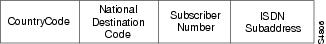
An E.164 number has a variable length; the maximum length is 15 digits. An E.164 number has the fields shown in Figure 2 and described in Table 28.
Figure 2 E.164 Address Format
Examples
In the following SVC example, if IP or AppleTalk triggers the call, the SVC is set up with the QoS parameters defined within the class "hawaii". An SVC triggered by either protocol results in two SVC maps, one for IP and one for AppleTalk. Two maps are set up because these protocol-and-address combinations are heading for the same destination, as defined by the dest-addr keyword and the values following it in the map-list command.
map-list bermuda source-addr E164 123456 dest-addr E164 654321ip 131.108.177.100 class hawaiiappletalk 1000.2 class hawaiiRelated Commands
Associates a map class with a protocol-and-address combination.
Specifies a map class to define QoS values for an SVC.
show frame-relay end-to-end keepalive
To display statistics about Frame Relay end-to-end keepalive, use the show frame-relay end-to-end keepalive EXEC command.
show frame-relay end-to-end keepalive [interface [DLCI]]
Syntax Description
Defaults
If no interface is specified, show all interfaces.
Command Modes
EXEC
Command History
Usage Guidelines
Use this command to display the keepalive status of an interface.
Examples
The following example shows output from the show frame-relay end-to-end keepalive command:
Router# show frame-relay end-to-end keepalive interface s1End-to-end Keepalive Statistics for Interface Serial1 (Frame Relay DTE)DLCI = 100, DLCI USAGE = LOCAL, VC STATUS = STATIC (EEK UP)SEND SIDE STATISTICSSend Sequence Number: 86, Receive Sequence Number: 87Configured Event Window: 3, Configured Error Threshold: 2Total Observed Events: 90, Total Observed Errors: 34Monitored Events: 3, Monitored Errors: 0Successive Successes: 3, End-to-end VC Status: UPRECEIVE SIDE STATISTICSSend Sequence Number: 88, Receive Sequence Number: 87Configured Event Window: 3, Configured Error Threshold: 2Total Observed Events: 90, Total Observed Errors: 33Monitored Events: 3, Monitored Errors: 0Successive Successes: 3, End-to-end VC Status: UPRelated Commands
show frame-relay fragment
To display information about the Frame Relay fragmentation, use the show frame-relay fragment command in privileged EXEC mode.
show frame-relay fragment [interface interface [DLCI]]
Syntax Description
Command Modes
Privileged EXEC
Command History
Usage Guidelines
When no parameters are specified with this command, the output displays a summary of each data-link connection identifier (DLCI) configured for fragmentation. The information displayed includes the fragmentation type, the configured fragment size, and the number of fragments transmitted, received, and dropped.
When a specific interface and DLCI are specified, additional details are displayed.
Examples
The following is sample output for the show frame-relay fragment command without any parameters specified:
Router# show frame-relay fragmentinterface dlci frag-type frag-size in-frag out-frag dropped-fragSerial0 108 VoFR-cisco 100 1261 1298 0Serial0 109 VoFR 100 0 243 0Serial0 110 end-to-end 100 0 0 0The following is sample output for the show frame-relay fragment command when an interface and DLCI are specified:
Router# show frame-relay fragment interface Serial1/0 16fragment-size 45 fragment type end-to-endin fragmented pkts 0 out fragmented pkts 0in fragmented bytes 0 out fragmented bytes 0in un-fragmented pkts 0 out un-fragmented pkts 0in un-fragmented bytes 0 out un-fragmented bytes 0in assembled pkts 0 out pre-fragmented pkts 0in assembled bytes 0 out pre-fragmented bytesin dropped reassembling pkts 0 out dropped fragmenting pkts 0in timeouts 0in out-of-sequence fragments 0in fragments with unexpected B bit set 0out interleaved packets 0Table 29 describes the fields shown in the display.
Related Commands
show frame-relay ip tcp header-compression
To display statistics and TCP/IP header compression information for the interface, use the show frame-relay ip tcp header-compression EXEC command.
show frame-relay ip tcp header-compression
Syntax Description
This command has no arguments or keywords.
Command Modes
EXEC
Command History
Examples
The following is sample output from the show frame-relay ip tcp header-compression command:
Router# show frame-relay ip tcp header-compressionDLCI 200 Link/Destination info: ip 10.108.177.200Interface Serial0:Rcvd: 40 total, 36 compressed, 0 errors0 dropped, 0 buffer copies, 0 buffer failuresSent: 0 total, 0 compressed0 bytes saved, 0 bytes sentConnect: 16 rx slots, 16 tx slots, 0 long searches, 0 misses, 0% hit ratioFive minute miss rate 0 misses/sec, 0 max misses/secTable 30 describes the fields shown in the display.
show frame-relay lapf
To display information about the status of the internals of Frame Relay Layer 2 (LAPF) if switched virtual circuits (SVCs) are configured, use the show frame-relay lapf EXEC command.
show frame-relay lapf
Syntax Description
This command has no arguments or keywords.
Command Modes
EXEC
Command History
Examples
The following is sample output from the show frame-relay lapf command.
Router# show frame-relay lapfInterface = Serial1 (up), LAPF state = TEI_ASSIGNED (down)SVC disabled, link down cause = LMI down, #link-reset = 0T200 = 1.5 sec., T203 = 30 sec., N200 = 3, k = 7, N201 = 260I xmt = 0, I rcv = 0, I reXmt = 0, I queued = 0I xmt dropped = 0, I rcv dropped = 0, Rcv pak dropped = 0RR xmt = 0, RR rcv = 0, RNR xmt = 0, RNR rcv = 0REJ xmt = 0, REJ rcv = 0, FRMR xmt = 0, FRMR rcv = 0DM xmt = 0, DM rcv = 0, DISC xmt = 0, DISC rcv = 0SABME xmt = 0, SABME rcv = 0, UA xmt = 0, UA rcv = 0V(S) = 0, V(A) = 0, V(R) = 0, N(S) = 0, N(R) = 0Xmt FRMR at Frame RejectTable 31 describes significant fields in this output.
show frame-relay lmi
To display statistics about the Local Management Interface (LMI), use the show frame-relay lmi EXEC command.
show frame-relay lmi [type number]
Syntax Description
Command Modes
EXEC
Command History
Usage Guidelines
Enter the command without arguments to obtain statistics about all Frame Relay interfaces.
Examples
The following is sample output from the show frame-relay lmi command when the interface is a data terminal equipment (DTE) device:
Router# show frame-relay lmiLMI Statistics for interface Serial1 (Frame Relay DTE) LMI TYPE = ANSIInvalid Unnumbered info 0 Invalid Prot Disc 0Invalid dummy Call Ref 0 Invalid Msg Type 0Invalid Status Message 0 Invalid Lock Shift 0Invalid Information ID 0 Invalid Report IE Len 0Invalid Report Request 0 Invalid Keep IE Len 0Num Status Enq. Sent 9 Num Status msgs Rcvd 0Num Update Status Rcvd 0 Num Status Timeouts 9The following is sample output from the show frame-relay lmi command when the interface is a Network-to-Network Interface (NNI):
Router# show frame-relay lmiLMI Statistics for interface Serial3 (Frame Relay NNI) LMI TYPE = CISCOInvalid Unnumbered info 0 Invalid Prot Disc 0Invalid dummy Call Ref 0 Invalid Msg Type 0Invalid Status Message 0 Invalid Lock Shift 0Invalid Information ID 0 Invalid Report IE Len 0Invalid Report Request 0 Invalid Keep IE Len 0Num Status Enq. Rcvd 11 Num Status msgs Sent 11Num Update Status Rcvd 0 Num St Enq. Timeouts 0Num Status Enq. Sent 10 Num Status msgs Rcvd 10Num Update Status Sent 0 Num Status Timeouts 0Table 32 describes significant fields shown in the output.
show frame-relay map
To display the current map entries and information about the connections, use the show frame-relay map EXEC command.
show frame-relay map
Syntax Description
This command has no arguments or keywords.
Command Modes
EXEC
Command History
Examples
The following is sample output from the show frame-relay map command:
Router# show frame-relay mapSerial 1 (administratively down): ip 10.108.177.177dlci 177 (0xB1,0x2C10), static,broadcast,CISCOTCP/IP Header Compression (inherited), passive (inherited)Table 33 describes significant fields shown in the display.
Related Commands
show frame-relay pvc
To display statistics about permanent virtual circuits (PVCs) for Frame Relay interfaces, use the show frame-relay pvc privileged EXEC command.
show frame-relay pvc [interface interface] [dlci]
Syntax Description
Command Modes
Privileged EXEC
Command History
Usage Guidelines
Use this command to monitor the PPP link control protocol (LCP) state as being open with an "up" state, or closed with a "down" state.
When "vofr" or "vofr cisco" has been configured on the PVC, and a voice bandwidth has been allocated to the class associated with this PVC, configured voice bandwidth and used voice bandwidth are also displayed.
Statistics Reporting
To obtain statistics about PVCs on all Frame Relay interfaces, use this command with no arguments. When you use the show frame-relay pvc command with no arguments or with the interface argument, a table will display that shows the number of PVCs in the various states.
To obtain statistics about a PVC that include policy-map configuration or the priority configured for that PVC, use this command with the dlci argument.
Per-VC counters are not incremented at all when either autonomous or silicon switching engine (SSE) switching is configured; therefore, PVC values will be inaccurate if either switching method is used.
Traffic Shaping
Congestion control mechanisms are currently not supported on terminated PVCs nor on PVCs over ISDN. Where congestion control mechanisms are supported, the switch passes forward explicit congestion notification (FECN) bits, backward explicit congestion notification (BECN) bits, and discard eligible (DE) bits unchanged from entry to exit points in the network.
Examples
The displays in this section show sample output for a variety of PVCs. Some of the PVCs carry data only; some carry a combination of voice and data.
Frame Relay Generic Configuration Example
The following sample output shows a generic Frame Relay configuration on DLCI 100:
Router# show frame-relay pvc 100PVC Statistics for interface Serial4/0/1:0 (Frame Relay DTE)DLCI = 100, DLCI USAGE = LOCAL, PVC STATUS = ACTIVE (EEK UP), INTERFACE = Serial4/0/1:0.1input pkts 4360 output pkts 4361 in bytes 146364out bytes 130252 dropped pkts 3735 in pkts dropped 0out pkts dropped 3735 out bytes dropped 1919790late-dropped out pkts 3735 late-dropped out bytes 1919790in FECN pkts 0 in BECN pkts 0 out FECN pkts 0out BECN pkts 0 in DE pkts 0 out DE pkts 0out bcast pkts 337 out bcast bytes 1020845 minute input rate 0 bits/sec, 0 packets/sec5 minute output rate 0 bits/sec, 0 packets/secpvc create time 05:34:06, last time pvc status changed 05:33:38Multiple Frame Relay PVCs Example
The following is sample output for the show frame-relay pvc command with no arguments. Statistics for all of the PVCs on all of the interfaces are displayed.
PVC Statistics for interface Serial2/1 (Frame Relay DTE)Active Inactive Deleted StaticLocal 115 0 0 0Switched 0 0 0 0Unused 0 0 0 0DLCI = 100, DLCI USAGE = LOCAL, PVC STATUS = ACTIVE, INTERFACE = Serial2/1input pkts 12 output pkts 7 in bytes 4406out bytes 1366 dropped pkts 0 in FECN pkts 0in BECN pkts 0 out FECN pkts 0 out BECN pkts 0in DE pkts 0 out DE pkts 0out bcast pkts 7 out bcast bytes 1366pvc create time 1d04h, last time pvc status changed 00:30:32--More--Frame Relay Fragmentation and Hardware Compression Example
The following is sample output for the show frame-relay pvc command for a PVC configured with Cisco-proprietary fragmentation and hardware compression:
Router# show frame-relay pvc 110PVC Statistics for interface Serial0/0 (Frame Relay DTE)DLCI = 110, DLCI USAGE = LOCAL, PVC STATUS = STATIC, INTERFACE = Serial0/0input pkts 409 output pkts 409 in bytes 3752out bytes 4560 dropped pkts 1 in FECN pkts 0in BECN pkts 0 out FECN pkts 0 out BECN pkts 0in DE pkts 0 out DE pkts 0out bcast pkts 0 out bcast bytes 0pvc create time 3d00h, last time pvc status changed 2d22hService type VoFR-ciscoVoice Queueing Stats: 0/100/0 (size/max/dropped)Post h/w compression queue: 0Current fair queue configuration:Discard Dynamic Reservedthreshold queue count queue count64 16 2Output queue size 0/max total 600/drops 0configured voice bandwidth 16000, used voice bandwidth 0fragment type VoFR-cisco fragment size 100cir 64000 bc 640 be 0 limit 80 interval 10mincir 32000 byte increment 80 BECN response nofrags 428 bytes 4810 frags delayed 24 bytes delayed 770shaping inactivetraffic shaping drops 0ip rtp priority parameters 16000 32000 20000Switched PVC Example
The following is sample output from the show frame-relay pvc command for a switched Frame Relay PVC. This output displays detailed information about NNI status and why packets were dropped from switched PVCs.
Router# show frame-relay pvcPVC Statistics for interface Serial2/2 (Frame Relay NNI)DLCI = 16, DLCI USAGE = SWITCHED, PVC STATUS = INACTIVE, INTERFACE = Serial2/2LOCAL PVC STATUS = INACTIVE, NNI PVC STATUS = INACTIVEinput pkts 0 output pkts 0 in bytes 0out bytes 0 dropped pkts 0 in FECN pkts 0in BECN pkts 0 out FECN pkts 0 out BECN pkts 0in DE pkts 0 out DE pkts 0out bcast pkts 0 out bcast bytes 0switched pkts0Detailed packet drop counters:no out intf 0 out intf down 0 no out PVC 0in PVC down 0 out PVC down 0 pkt too big 0shaping Q full 0 pkt above DE 0 policing drop 0pvc create time 00:00:07, last time pvc status changed 00:00:07Frame Relay Congestion Management on a Switched PVC Example
The following is sample output from the show frame-relay pvc command that shows the statistics for a switched PVC on which Frame Relay congestion management is configured:
Router# show frame-relay pvc 200PVC Statistics for interface Serial3/0 (Frame Relay DTE)DLCI = 200, DLCI USAGE = SWITCHED, PVC STATUS = ACTIVE, INTERFACE = Serial3/0input pkts 341 output pkts 390 in bytes 341000out bytes 390000 dropped pkts 0 in FECN pkts 0in BECN pkts 0 out FECN pkts 0 out BECN pkts 0in DE pkts 0 out DE pkts 390out bcast pkts 0 out bcast bytes 0 Num Pkts Switched 341pvc create time 00:10:35, last time pvc status changed 00:10:06Congestion DE threshold 50shaping activecir 56000 bc 7000 be 0 byte limit 875 interval 125mincir 28000 byte increment 875 BECN response nopkts 346 bytes 346000 pkts delayed 339 bytes delayed 339000traffic shaping drops 0Queueing strategy:fifoOutput queue 48/100, 0 drop, 339 dequeuedFrame Relay Policing on a Switched PVC Example
The following is sample output from the show frame-relay pvc command that shows the statistics for a switched PVC on which Frame Relay policing is configured:
Router# show frame-relay pvc 100PVC Statistics for interface Serial1/0 (Frame Relay DCE)DLCI = 100, DLCI USAGE = SWITCHED, PVC STATUS = ACTIVE, INTERFACE = Serial1/0input pkts 1260 output pkts 0 in bytes 1260000out bytes 0 dropped pkts 0 in FECN pkts 0in BECN pkts 0 out FECN pkts 0 out BECN pkts 0in DE pkts 0 out DE pkts 0out bcast pkts 0 out bcast bytes 0 Num Pkts Switched 1260pvc create time 00:03:57, last time pvc status changed 00:03:19policing enabled, 180 pkts marked DEpolicing Bc 6000 policing Be 6000 policing Tc 125 (msec)in Bc pkts 1080 in Be pkts 180 in xs pkts 0in Bc bytes 1080000 in Be bytes 180000 in xs bytes 0Frame Relay PVC Priority Queueing Example
The following is sample output for a PVC that has been assigned high priority:
Router# show frame-relay pvc 100PVC Statistics for interface Serial0 (Frame Relay DTE)DLCI = 100, DLCI USAGE = LOCAL, PVC STATUS = ACTIVE, INTERFACE = Serial0input pkts 0 output pkts 0 in bytes 0out bytes 0 dropped pkts 0 in FECN pkts 0in BECN pkts 0 out FECN pkts 0 out BECN pkts 0in DE pkts 0 out DE pkts 0out bcast pkts 0 out bcast bytes 0pvc create time 00:00:59, last time pvc status changed 00:00:33priority highLow Latency Queueing for Frame Relay Example
The following is sample output from the show frame-relay pvc command for a PVC shaped to a 64K committed information rate (CIR) with fragmentation. A policy map is attached to the PVC and is configured with a priority class for voice, two data classes for IP precedence traffic, and a default class for best-effort traffic. Weighted Random Early Detection (WRED) is used as the drop policy on one of the data classes.
Router# show frame-relay pvc 100PVC Statistics for interface Serial1/0 (Frame Relay DTE)DLCI = 100, DLCI USAGE = LOCAL, PVC STATUS = INACTIVE, INTERFACE = Serial1/0.1input pkts 0 output pkts 0 in bytes 0out bytes 0 dropped pkts 0 in FECN pkts 0in BECN pkts 0 out FECN pkts 0 out BECN pkts 0in DE pkts 0 out DE pkts 0out bcast pkts 0 out bcast bytes 0pvc create time 00:00:42, last time pvc status changed 00:00:42service policy mypolicyClass voiceWeighted Fair QueueingStrict PriorityOutput Queue: Conversation 72Bandwidth 16 (kbps) Packets Matched 0(pkts discards/bytes discards) 0/0Class immediate-dataWeighted Fair QueueingOutput Queue: Conversation 73Bandwidth 60 (%) Packets Matched 0(pkts discards/bytes discards/tail drops) 0/0/0mean queue depth: 0drops: class random tail min-th max-th mark-prob0 0 0 64 128 1/101 0 0 71 128 1/102 0 0 78 128 1/103 0 0 85 128 1/104 0 0 92 128 1/105 0 0 99 128 1/106 0 0 106 128 1/107 0 0 113 128 1/10rsvp 0 0 120 128 1/10Class priority-dataWeighted Fair QueueingOutput Queue: Conversation 74Bandwidth 40 (%) Packets Matched 0 Max Threshold 64 (packets)(pkts discards/bytes discards/tail drops) 0/0/0Class class-defaultWeighted Fair QueueingFlow Based Fair QueueingMaximum Number of Hashed Queues 64 Max Threshold 20 (packets)Output queue size 0/max total 600/drops 0fragment type end-to-end fragment size 50cir 64000 bc 640 be 0 limit 80 interval 10mincir 64000 byte increment 80 BECN response nofrags 0 bytes 0 frags delayed 0 bytes delayed 0shaping inactivetraffic shaping drops 0PPP over Frame Relay Example
The following is sample output from the show frame-relay pvc command that shows the PVC statistics for serial interface 5 (slot 1 and DLCI 55 are up) during a PPP session over Frame Relay:
Router# show frame-relay pvc 55PVC Statistics for interface Serial5/1 (Frame Relay DTE)DLCI = 55, DLCI USAGE = LOCAL, PVC STATUS = ACTIVE, INTERFACE = Serial5/1.1input pkts 9 output pkts 16 in bytes 154out bytes 338 dropped pkts 6 in FECN pkts 0in BECN pkts 0 out FECN pkts 0 out BECN pkts 0in DE pkts 0 out DE pkts 0out bcast pkts 0 out bcast bytes 0pvc create time 00:35:11, last time pvc status changed 00:00:22Bound to Virtual-Access1 (up, cloned from Virtual-Template5)Voice over Frame Relay Example
The following is sample output from the show frame-relay pvc command for a PVC carrying Voice over Frame Relay (VoFR) traffic configured via the vofr cisco command. The frame-relay voice bandwidth command has been configured on the class associated with this PVC, as has fragmentation. The fragmentation employed is proprietary to Cisco.
A sample configuration for this scenario is shown first, followed by the output for the show frame-relay pvc command.
interface serial 0encapsulation frame-relayframe-relay traffic-shapingframe-relay interface-dlci 108vofr ciscoclass vofr-classmap-class frame-relay vofr-classframe-relay fragment 100frame-relay fair-queueframe-relay cir 64000frame-relay voice bandwidth 25000Router# show frame-relay pvc 108PVC Statistics for interface Serial0 (Frame Relay DTE)DLCI = 108, DLCI USAGE = LOCAL, PVC STATUS = STATIC, INTERFACE = Serial0input pkts 1260 output pkts 1271 in bytes 95671out bytes 98604 dropped pkts 0 in FECN pkts 0in BECN pkts 0 out FECN pkts 0 out BECN pkts 0in DE pkts 0 out DE pkts 0out bcast pkts 1271 out bcast bytes 98604pvc create time 09:43:17, last time pvc status changed 09:43:17Service type VoFR-ciscoconfigured voice bandwidth 25000, used voice bandwidth 0voice reserved queues 24, 25fragment type VoFR-cisco fragment size 100cir 64000 bc 64000 be 0 limit 1000 interval 125mincir 32000 byte increment 1000 BECN response nopkts 2592 bytes 205140 pkts delayed 1296 bytes delayed 102570shaping inactiveshaping drops 0Current fair queue configuration:Discard Dynamic Reservedthreshold queue count queue count64 16 2Output queue size 0/max total 600/drops 0FRF.12 Fragmentation Example
The following is sample output from the show frame-relay pvc command for an application employing pure FRF.12 fragmentation. A sample configuration for this scenario is shown first, followed by the output for the show frame-relay pvc command.
interface serial 0encapsulation frame-relayframe-relay traffic-shapingframe-relay interface-dlci 110class fragmap-class frame-relay fragframe-relay fragment 100frame-relay fair-queueframe-relay cir 64000Router# show frame-relay pvc 110PVC Statistics for interface Serial0 (Frame Relay DTE)DLCI = 110, DLCI USAGE = LOCAL, PVC STATUS = STATIC, INTERFACE = Serial0input pkts 0 output pkts 243 in bytes 0out bytes 7290 dropped pkts 0 in FECN pkts 0in BECN pkts 0 out FECN pkts 0 out BECN pkts 0in DE pkts 0 out DE pkts 0out bcast pkts 243 out bcast bytes 7290pvc create time 04:03:17, last time pvc status changed 04:03:18fragment type end-to-end fragment size 100cir 64000 bc 64000 be 0 limit 1000 interval 125mincir 32000 byte increment 1000 BECN response nopkts 486 bytes 14580 pkts delayed 243 bytes delayed 7290shaping inactiveshaping drops 0Current fair queue configuration:Discard Dynamic Reservedthreshold queue count queue count64 16 2Output queue size 0/max total 600/drops 0Note that when voice is not configured, voice bandwidth output is not displayed.
PVC Transporting Voice and Data
The following is sample output from the show frame-relay pvc command for a PVC carrying voice and data traffic, with a special queue specifically for voice traffic created using the frame-relay voice bandwidth command queue keyword:
Router# show frame-relay pvc interface serial 1 45PVC Statistics for interface Serial1 (Frame Relay DTE)DLCI = 45, DLCI USAGE = LOCAL, PVC STATUS = STATIC, INTERFACE = Serial1input pkts 85 output pkts 289 in bytes 1730out bytes 6580 dropped pkts 11 in FECN pkts 0in BECN pkts 0 out FECN pkts 0 out BECN pkts 0in DE pkts 0 out DE pkts 0out bcast pkts 0 out bcast bytes 0pvc create time 00:02:09, last time pvc status changed 00:02:09Service type VoFRconfigured voice bandwidth 25000, used voice bandwidth 22000fragment type VoFR fragment size 100cir 20000 bc 1000 be 0 limit 125 interval 50mincir 20000 byte increment 125 BECN response nofragments 290 bytes 6613 fragments delayed 1 bytes delayed 33shaping inactivetraffic shaping drops 0Voice Queueing Stats: 0/100/0 (size/max/dropped)~~~~~~~~~~~~~~~~~~~~~~~~~~~~~~~~~~~~~~~~~~~~~~~~~Current fair queue configuration:Discard Dynamic Reservedthreshold queue count queue count64 16 2Output queue size 0/max total 600/drops 0Table 34 describes the significant fields shown in the display.
Table 34 show frame-relay pvc Field Descriptions
DLCI
One of the DLCI numbers for the PVC.
DLCI USAGE
Lists SWITCHED when the router or access server is used as a switch, or LOCAL when the router or access server is used as a DTE device.
PVC STATUS
Status of the PVC. The DCE device reports the status, and the DTE device receives the status. When you disable the Local Management Interface (LMI) mechanism on the interface (by using the no keepalive command), the PVC status is STATIC. Otherwise, the PVC status is exchanged using the LMI protocol:
•
STATIC—LMI is disabled on the interface.
•
•
•
If the frame-relay end-to-end keepalive command is used, the end-to-end keepalive (EEK) status is reported in addition to the LMI status. For example:
•
•
INTERFACE
Specific subinterface associated with this DLCI.
LOCAL PVC STATUS1
Status of PVC configured locally on the NNI interface.
NNI PVC STATUS1
Status of PVC learned over the NNI link.
input pkts
Number of packets received on this PVC.
output pkts
Number of packets sent on this PVC.
in bytes
Number of bytes received on this PVC.
out bytes
Number of bytes sent on this PVC.
dropped pkts
Number of incoming and outgoing packets dropped by the router at the Frame Relay level.
in pkts dropped
Number of incoming packets dropped. Incoming packets may be dropped for a number of reasons, including the following:
•
•
•
•
•
•
out pkts dropped
Number of outgoing packets dropped, including shaping drops and late drops.
out bytes dropped
Number of outgoing bytes dropped.
late-dropped out pkts
Number of outgoing packets dropped because of QoS policy (such as with VC queuing or Frame Relay traffic shaping). This field is not displayed when the value is zero.
late-dropped out bytes
Number of outgoing bytes dropped because of QoS policy (such with as VC queuing or Frame Relay traffic shaping). This field is not displayed when the value is zero.
in FECN pkts
Number of packets received with the FECN bit set.
in BECN pkts
Number of packets received with the BECN bit set.
out FECN pkts
Number of packets sent with the FECN bit set.
out BECN pkts
Number of packets sent with the BECN bit set.
in DE pkts
Number of DE packets received.
out DE pkts
Number of DE packets sent.
out bcast pkts
Number of output broadcast packets.
out bcast bytes
Number of output broadcast bytes.
switched pkts
Number of switched packets.
no out intf2
Number of packets dropped because there is no output interface.
out intf down2
Number of packets dropped because the output interface is down.
no out PVC2
Number of packets dropped because the outgoing PVC is not configured.
in PVC down2
Number of packets dropped because the incoming PVC is inactive.
out PVC down2
Number of packets dropped because the outgoing PVC is inactive.
pkt too big2
Number of packets dropped because the packet size is greater than media MTU3 .
shaping Q full2
Number of packets dropped because the Frame Relay traffic-shaping queue is full.
pkt above DE2
Number of packets dropped because they are above the DE level when Frame Relay congestion management is enabled.
policing drop2
Number of packets dropped because of Frame Relay traffic policing.
pvc create time
Time at which the PVC was created.
last time pvc status changed
Time at which the PVC changed status.
VC-Bundle
PVC bundle of which the PVC is a member.
priority
Priority assigned to the PVC.
pkts marked DE
Number of packets marked DE because they exceeded the Bc.
policing Bc
Committed burst size.
policing Be
Excess burst size.
policing Tc
Measurement interval for counting Bc and Be.
in Bc pkts
Number of packets received within the committed burst.
in Be pkts
Number of packets received within the excess burst.
in xs pkts
Number of packets dropped because they exceeded the combined burst.
in Bc bytes
Number of bytes received within the committed burst.
in Be bytes
Number of bytes received within the excess burst.
in xs bytes
Number of bytes dropped because they exceeded the combined burst.
Congestion DE threshold
PVC queue percentage at which packets with the DE bit are dropped.
Congestion ECN threshold
PVC queue percentage at which packets are set with the BECN and FECN bits.
Service type
Type of service performed by this PVC. Can be VoFR or VoFR-cisco.
Post h/w compression queue
Number of packets in the post-hardware-compression queue when hardware compression and Frame Relay fragmentation are configured.
configured voice bandwidth
Amount of bandwidth in bits per second (bps) reserved for voice traffic on this PVC.
used voice bandwidth
Amount of bandwidth in bps currently being used for voice traffic.
service policy
Name of the output service policy applied to the VC.
Class
Class of traffic being displayed. Output is displayed for each configured class in the policy.
Output Queue
The WFQ4 conversation to which this class of traffic is allocated.
Bandwidth
Bandwidth in kbps or percentage configured for this class.
Packets Matched
Number of packets that matched this class.
Max Threshold
Maximum queue size for this class when WRED is not used.
pkts discards
Number of packets discarded for this class.
bytes discards
Number of bytes discarded for this class.
tail drops
Number of packets discarded for this class because the queue was full.
mean queue depth
Average queue depth, based on the actual queue depth on the interface and the exponential weighting constant. It is a moving average. The minimum and maximum thresholds are compared against this value to determine drop decisions.
drops:
WRED parameters.
class
IP precedence value.
random
Number of packets randomly dropped when the mean queue depth is between the minimum threshold value and the maximum threshold value for the specified IP precedence value.
tail
Number of packets dropped when the mean queue depth is greater than the maximum threshold value for the specified IP precedence value.
min-th
Minimum WRED threshold in number of packets.
max-th
Maximum WRED threshold in number of packets.
mark-prob
Fraction of packets dropped when the average queue depth is at the maximum threshold.
Maximum Number of Hashed Queues
(Applies to class default only) Number of queues available for unclassified flows.
fragment type
Type of fragmentation configured for this PVC. Possible types are as follows:
•
•
•
fragment size
Size of the fragment payload in bytes.
adaptive active/inactive
Indicates whether Frame Relay voice-adaptive fragmentation is active or inactive.
time left
Number of seconds left on the Frame Relay voice-adaptive fragmentation deactivation timer. When this timer expires, Frame Relay fragmentation turns off.
cir
Current CIR in bps.
bc
Current committed burst (Bc) size, in bits.
be
Current excess burst (Be) size, in bits.
limit
Maximum number of bytes sent per internal interval (excess plus sustained).
interval
Interval being used internally (may be smaller than the interval derived from Bc/CIR; this happens when the router determines that traffic flow will be more stable with a smaller configured interval).
mincir
Minimum CIR for the PVC.
byte increment
Number of bytes that will be sustained per internal interval.
BECN response
Indication that Frame Relay has BECN adaptation configured.
pkts
Number of packets associated with this PVC that have gone through the traffic-shaping system.
frags
Total number of fragments (and unfragmented packets that are too small to be fragmented) shaped on this VC.
bytes
Number of bytes associated with this PVC that have gone through the traffic-shaping system.
pkts delayed
Number of packets associated with this PVC that have been delayed by the traffic-shaping system.
frags delayed
Number of fragments (and unfragmented packets that are too small to be fragmented) delayed in the shaping queue before being sent.
bytes delayed
Number of bytes associated with this PVC that have been delayed by the traffic-shaping system.
shaping
Indication that shaping will be active for all PVCs that are fragmenting data; otherwise, shaping will be active if the traffic being sent exceeds the CIR for this circuit.
shaping drops
Number of packets dropped by the traffic-shaping process.
Queueing strategy
Per-VC queueing strategy.
Output queue
48/100
0 drop
300 dequeued
State of the per-VC queue.
•
•
•
Voice Queueing Stats
Statistics showing the size of packets, the maximum number of packets, and the number of packets dropped in the special voice queue created using the frame-relay voice bandwidth command queue keyword.
Discard threshold
Maximum number of packets that can be stored in each packet queue. Additional packets received after a queue is full will be discarded.
Dynamic queue count
Number of packet queues reserved for best-effort traffic.
Reserved queue count
Number of packet queues reserved for voice traffic.
Output queue size
Size in bytes of each output queue.
max total
Maximum number of packets of all types that can be queued in all queues.
drops
Number of frames dropped by all output queues.
1 The LOCAL PVC STATUS and NNI PVC STATUS fields are displayed only for PVCs configured on Frame Relay NNI interface types. These fields are not displayed if the PVC is configured on DCE or DTE interface types.
2 The detailed packet drop fields are displayed for switched Frame Relay PVCs only. These fields are not displayed for terminated PVCs.
3 MTU = maximum transmission unit
4 WFQ = weighted fair queueing
Related Commands
show frame-relay qos-autosense
To display the quality of service (QoS) values sensed from the switch, use the show frame-relay qos-autosense EXEC command.
show frame-relay qos-autosense [interface number]
Syntax Description
interface number
(Optional) Indicates the number of the physical interface for which you want to display QoS information.
Command Modes
EXEC
Command History
11.2
This command was introduced.
12.1(3)T
This command was modified to display information about Enhanced Local Management Interface (ELMI) address registration.
Examples
The following is sample output from the show frame-relay qos-autosense command when ELMI and ELMI address registration are enabled.
Router# show frame-relay qos-autosenseELMI information for interface Serial1IP Address used for Address Registration:9.2.7.9 My Ifindex:4ELMI AR status : Enabled.Connected to switch:hgw1 Platform:2611 Vendor:ciscoSw side ELMI AR status: EnabledIP Address used by switch for address registration :9.2.6.9 Ifindex:5ELMI AR status : Enabled.(Time elapsed since last update 00:00:40)The following is sample output from the show frame-relay qos-autosense command when ELMI and traffic shaping are enabled:
Router# show frame-relay qos-autosenseELMI information for interface Serial1Connected to switch:FRSM-4T1 Platform:AXIS Vendor:cisco(Time elapsed since last update 00:00:30)DLCI = 100OUT: CIR 64000 BC 50000 BE 25000 FMIF 4497IN: CIR 32000 BC 25000 BE 12500 FMIF 4497Priority 0 (Time elapsed since last update 00:00:12)DLCI = 200OUT: CIR 128000 BC 50000 BE 5100 FMIF 4497IN: CIR Unknown BC Unknown BE Unknown FMIF 4497Priority 0 (Time elapsed since last update 00:00:13)Table 35 describes the significant fields in the output display.
Related Commands
Enables ELMI on the Cisco router.
Displays statistics about PVCs for Frame Relay interfaces.
show frame-relay route
To display all configured Frame Relay routes, along with their status, use the show frame-relay route EXEC command.
show frame-relay route
Syntax Description
This command has no arguments or keywords.
Command Modes
EXEC
Command History
Examples
The following is sample output from the show frame-relay route command:
Router# show frame-relay routeInput Intf Input Dlci Output Intf Output Dlci StatusSerial1 100 Serial2 200 activeSerial1 101 Serial2 201 activeSerial1 102 Serial2 202 activeSerial1 103 Serial3 203 inactiveSerial2 200 Serial1 100 activeSerial2 201 Serial1 101 activeSerial2 202 Serial1 102 activeSerial3 203 Serial1 103 inactiveTable 36 describes significant fields shown in the output.
show frame-relay svc maplist
To display all the switched virtual circuits (SVCs) under a specified map list, use the show frame-relay svc maplist EXEC command.
show frame-relay svc maplist name
Syntax Description
Command Modes
EXEC
Command History
Examples
The following example shows, first, the configuration of the shank map list and, second, the corresponding output of the show frame-relay svc maplist command. The following lines show the configuration:
map-list shank local-addr X121 87654321 dest-addr X121 12345678ip 172.21.177.26 class shank ietfipx 123.0000.0c07.d530 class shank ietf!map-class frame-relay shankframe-relay incir 192000frame-relay min-incir 19200frame-relay outcir 192000frame-relay min-outcir 19200frame-relay incbr(bytes) 15000frame-relay outcbr(bytes) 15000The following lines show the output of the show frame-relay svc maplist command for the preceding configuration:
Router# show frame-relay svc maplist shankMap List : shankLocal Address : 87654321 Type: X121Destination Address: 12345678 Type: X121Protocol : ip 172.21.177.26Protocol : ipx 123.0000.0c07.d530Encapsulation : IETFCall Reference : 1 DLCI : 501Configured Frame Mode Information Field Size :Incoming : 1500 Outgoing : 1500Frame Mode Information Field Size :Incoming : 1500 Outgoing : 1500Configured Committed Information Rate (CIR) :Incoming : 192 * (10**3) Outgoing : 192 * (10**3)Committed Information Rate (CIR) :Incoming : 192 * (10**3) Outgoing : 192 * (10**3)Configured Minimum Acceptable CIR :Incoming : 192 * (10**2) Outgoing : 192 * (10**2)Minimum Acceptable CIR :Incoming : 0 * (10**0) Outgoing : 0 * (10**0)Configured Committed Burst Rate (bytes) :Incoming : 15000 Outgoing : 15000Committed Burst Rate (bytes) :Incoming : 15000 Outgoing : 15000Configured Excess Burst Rate (bytes) :Incoming : 16000 Outgoing : 1200Excess Burst Rate (bytes) :Incoming : 16000 Outgoing : 1200Table 37 describes significant fields in the output.
Related Commands
show frame-relay traffic
To display the global Frame Relay statistics since the last reload, use the show frame-relay traffic EXEC command.
show frame-relay traffic
Syntax Description
This command has no arguments or keywords.
Command Modes
EXEC
Command History
Examples
The following is sample output from the show frame-relay traffic command:
Router# show frame-relay trafficFrame Relay statistics:ARP requests sent 14, ARP replies sent 0ARP request recvd 0, ARP replies recvd 10threshold de
To configure the threshold at which discard eligible (DE)-marked packets will be discarded from switched permanent virtual circuits (PVCs) on the output interface, use the threshold de Frame Relay congestion management configuration command. To remove the threshold configuration, use the no form of this command.
threshold de percentage
no threshold de percentage
Syntax Description
percentage
Threshold at which DE-marked packets will be discarded, specified as a percentage of maximum queue size.
Defaults
100%
Command Modes
Frame Relay congestion management configuration
Command History
Usage Guidelines
You must enable Frame Relay congestion management on the interface before congestion management parameters will be effective. To enable Frame Relay congestion management and to enter Frame Relay congestion management configuration mode, use the frame-relay congestion-management interface command.
You must enable Frame Relay switching, using the frame-relay switching global command, before the threshold de command will be effective on switched PVCs.
Examples
The following example shows how to configure a DE threshold of 40% on serial interface 1.
interface serial1encapsulation frame-relayframe-relay congestion-managementthreshold de 40Related Commands
threshold ecn
To configure the threshold at which ECN bits will be set on packets in switched PVCs on the output interface, use the threshold ecn Frame Relay congestion management configuration command. To remove the threshold configuration, use the no form of this command.
threshold ecn {bc | be} percentage
no threshold ecn {bc | be} percentage
Syntax Description
Defaults
100%
Command Modes
Frame Relay congestion management
Command History
Usage Guidelines
You must enable Frame Relay congestion management on the interface before congestion management parameters will be effective. To enable Frame Relay congestion management and to enter Frame Relay congestion management configuration mode, use the frame-relay congestion-management interface command.
You must enable Frame Relay switching, using the frame-relay switching global command, before the threshold ecn command will be effective on switched PVCs.
You can configure separate queue thresholds for committed and excess traffic.
Configure the Be ECN threshold so that it is greater than or equal to zero and less than or equal to the Bc ECN threshold. Configure the Bc ECN threshold so that it is less than or equal to 100.
Examples
The following example shows how to configure a Be threshold of 0 and a Bc threshold of 20% on serial interface 1.
interface serial1encapsulation frame-relayframe-relay congestion-managementthreshold ecn be 0threshold ecn bc 20Related Commands