-
Cisco IOS Dial Technologies Command Reference, Release 12.2
-
Using Cisco IOS Software
-
Commands A through CAS
-
Commands CHA through CPP
-
Commands D
-
Commands EN through IP
-
Commands IS through L2
-
Commands LCP through MOD
-
Commands MU through PPP
-
Commands PRI through SHE
-
Commands SHOW A through SHOW DI
-
Commands SHOW DS through SHOW LI
-
Commands SHOW M through SHOW N
-
Commands SHOW P through SHOW R
-
Commands SHOW S through SHOW V
-
Commands SHU through X
-
Index
-
 Feedback
Table Of Contents
ppp multilink fragment disable
ppp multilink fragment maximum
ppp timeout multilink link add
ppp timeout multilink link remove
ppp timeout multilink lost-fragment
pptp flow-control receive-window
multilink
To limit the total number multilink PPP (MLP) sessions for all virtual private dialup network (VPDN) multilink users, enter the multilink command in VPDN group configuration mode. To remove the MLP session limit, enter the no form of this command.
multilink {bundle bundles | link links}
no multilink {bundle bundles | link links}
Syntax Description
Command Default
No MLP session limit is set.
Command Modes
VPDN group configuration
Command History
12.0(4)XI
This command was introduced.
12.0(5)T
This command was integrated into Cisco IOS Release 12.0(5)T.
Usage Guidelines
Use the multilink VPDN group configuration command to limit the total number of sessions for all MLP users. Each user requires one bundle, regardless if the user is a remote modem client or an ISDN client.
One modem client using one B channel requires one link. One ISDN BRI node may require up to two links for one BRI line connection. The second B channel of an ISDN BRI node comes up when the maximum threshold is exceeded.
Examples
The following example configures a VPDN group called group1 to initiate Layer 2 Tunnel Protocol (L2TP) tunnels to the tunnel server at IP address 10.2.2.2. Ten MLP bundles are configured for users that dial in to the domain cisco.com. Each bundle is configured to support a maximum of 5 links, limiting the total number of MLP sessions to 50.
Router(config)# vpdn-group group1Router(config-vpdn)# request-dialinRouter(config-vpdn-req-in)# protocol l2tpRouter(config-vpdn-req-in)# domain cisco.comRouter(config-vpdn-req-in)# exitRouter(config-vpdn)# initiate-to ip 10.2.2.2Router(config-vpdn)# multilink bundle 10Router(config-vpdn)# multilink link 5Related Commands
multilink bundle-name
To select a method for naming multilink bundles, use the multilink bundle-name command in global configuration mode. To remove the selection method, use the no form of this command.
multilink bundle-name {authenticated | endpoint | both}
no multilink bundle-name {authenticated | endpoint | both}
Syntax Description
authenticated
Authenticated name of the peer. This is the default.
endpoint
Endpoint discriminator of the peer.
both
Authenticated name and endpoint discriminator of the peer.
Defaults
Authenticated name of the peer.
Command Modes
Global configuration
Command History
Usage Guidelines
The authenticated keyword defines the selection criteria for the bundle name as the authenticated name, the endpoint discriminator if the link is not authenticated, or the caller ID if neither an authenticated name nor an endpoint is supplied.
The endpoint keyword defines the selection criteria for the bundle name as the endpoint discriminator, the authenticated name if no endpoint is supplied, or the caller ID if neither an authenticated name nor an endpoint is supplied.
The both keyword defines the selection criteria for the bundle name as an authenticated name-endpoint discriminator pair, the authenticated name if no endpoint is supplied, the endpoint discriminator if the link is not authenticated, or the caller ID if neither an authenticated name nor an endpoint is supplied.
Examples
The following example sets the selection criteria for the multilink bundle name as the endpoint discriminator:
multilink bundle-name endpointmultilink-group
The multilink-group command is replaced by the ppp multilink group command. See the description of the ppp multilink group command for more information.
Note
The command is still recognized and accepted by the Cisco IOS software. The show running-config and write memory commands will display and generate the original command in Cisco IOS Release 12.2.
multilink max-fragments
The multilink max-fragments command is replaced by the ppp multilink fragment maximum command. See the description of the ppp multilink fragment maximum command for more information.
multilink virtual-template
To specify a virtual template from which the specified Multilink PPP (MLP) bundle interface can clone its interface parameters, use the multilink virtual-template command in global configuration mode. To remove the defined virtual template, use the no form of the command.
multilink virtual-template number
no multilink virtual-template number
Syntax Description
number
Number of virtual templates. An integer in the range from 1 to the largest number of virtual templates the software image supports (typically 25).
Defaults
No template number is defined.
Command Modes
Global configuration
Command History
Usage Guidelines
Configuring a specific IP address in a virtual template can result in the establishment of erroneous routes and the loss of IP packets.
Examples
The following example specifies an MLP virtual template to be used and then defines the template to be applied to an MLP bundle interface:
multilink virtual-template 1interface virtual-template 1ip unnumbered ethernet 0encapsulation pppppp multilinkppp authentication chapRelated Commands
Creates a virtual template interface that can be configured and applied dynamically in creating virtual access interfaces.
name (dial peer cor custom)
To specify the name for a custom class of restrictions (COR), use the name command in dial peer COR custom configuration mode. To remove a specified COR, use the no form of this command.
name class-name
no name class-name
Syntax Description
Defaults
No default behavior or values.
Command Modes
Dial peer COR custom configuration
Command History
Usage Guidelines
The dial-peer cor custom and name commands define the names of capabilities on which to apply COR operation. Examples of names might include any of the following: call1900, call527, call9, or call 911. You must define the capabilities before you specify the COR rules.
You can define a maximum of 64 COR names.
Examples
The following example defines three COR names:
dial-peer cor customname 900_callname 800_callname catchallRelated Commands
netbios nbf
To enable the NetBIOS Frames Protocol (NBF) on an interface, use the netbios nbf command in interface configuration mode. To disable NetBIOS Frames Protocol support on an interface, use the no form of this command.
netbios nbf
no netbios nbf
Syntax Description
This command has no arguments or keywords.
Defaults
Command is disabled.
Command Modes
Interface configuration
Command History
Examples
The following example enables NBF on asynchronous interface 1 (connected to remote access client using a NetBEUI application) and Ethernet interface 0 (connected to the remote router):
interface async 1netbios nbfinterface ethernet 0netbios nbfRelated Commands
network-clock-priority
To specify the clock-recovery priority for the BRI voice ports in a BRI voice module (BVM), use the network-clock-priority command in interface configuration mode. To restore the default (low) clock-recovery priority, use the no form of this command.
network-clock-priority {low | high}
no network-clock-priority {low | high}
Syntax Description
low
The BRI port is second priority to recover clock.
high
The BRI port is first priority to recover clock.
Defaults
Each BRI voice port has low clock-recovery priority. The BRI VIC port provides clocking (high).
Command Modes
Interface configuration
Command History
12.0(3)XG
This command was introduced on the Cisco MC3810 concentrator.
12.1(3)XI
This command was implemented on the Cisco 2600 series and Cisco 3600 series.
Usage Guidelines
Because the BRI VIC can support both NT and TE ports, this command allows a "local loop" to be configured for testing. By default the TE port on the BRI VIC receives the clock source to drive the whole BRI (network-clock-priority high). Setting the clock priority to low allows the connected port to provide clocking.
This command becomes effective only when the BVM is the clock source for the Cisco MC3810, which can happen in one of three ways:
•
•
•
The BRI voice port supplying clock operates as a line source; if there are other BRI voice ports configured as TE, they operate in loop-timed mode.
Regardless of the network-clock-priority setting, the first TE-configured BRI voice port that becomes active is automatically chosen to supply clock. The clock source does not change if another BRI voice port configured for network-clock-priority high becomes active.
If the chosen clocking port becomes inactive, the system searches for clock on the active TE-configured ports in the following order:
1.
2.
If the originally chosen port then reactivates, it resumes its role as clock source regardless of its network-clock-priority setting.
If you enter either the no network-clock-priority low or the no network-clock-priority high command, the network clock priority defaults to low.
Examples
The following example configures BRI voice port 1 as a first priority clock source:
interface bri 0/1network-clock-priority highRelated Commands
number
To add a Calling Line Identification (CLID) or Dialed Number Identification Service (DNIS) number to a dialer group, use the number command in CLID group configuration or DNIS group configuration mode followed by the specifying number. To remove a number from a group, use the no form of this command.
number ID-number
no number ID-number
Syntax Description
Note
Defaults
No default behavior or values.
Command Modes
CLID group configuration
DNIS group configurationCommand History
12.0(4)XI
This command was introduced.
12.1(5)T
This command was enhanced to add CLID numbers to a CLID group and DNIS numbers to a DNIS group.
Usage Guidelines
You can organize CLID numbers for a customer or service type into a CLID group. You can add multiple CLID groups to a customer profile. Add all CLID numbers into one CLID group, or subdivide the CLID numbers using criteria such as call type, geographical location, or division.
The Cisco IOS software also includes a feature that streamlines the DNIS configuration process. By replacing any digit with an X (for example, issuing the number 555222121x command), clients dialing different numbers, such as 5552221214 or 5552221215, are automatically mapped to the same customer profile. The X variable is a placeholder for the digits 1 through 9.
Examples
The following example shows the command to use to assign a number to a CLID group named "zot":
dialer clid group zotnumber 2121212121The following example shows a DNIS group called dnis_isp_1 and DNIS numbers 1234 and 5678 assigned to the DNIS group:
dialer dnis group dnis_isp_1number 1234number 5678Related Commands
Adds a CLID group to a discriminator.
dnis group
Includes a group of DNIS numbers in a customer profile.
Creates a call discrimination profile.
peer default ip address
To specify an IP address, an address from a specific IP address pool, or an address from the Dynamic Host Configuration Protocol (DHCP) mechanism to be returned to a remote peer connecting to this interface, use the peer default ip address command in interface configuration mode. To disable a prior peer IP address pooling configuration on an interface, or to remove the default address from your configuration, use the no form of this command.
peer default ip address {ip-address | dhcp | pool [pool-name-list]}
no peer default ip address
Syntax Description
Defaults
The default is pool.
Command Modes
Interface configuration
Command History
Usage Guidelines
This command applies to point-to-point interfaces that support the PPP or Serial Line Internet Protocol (SLIP) encapsulation. This command sets the address used on the remote (PC) side.
Note
This command allows an administrator to configure all possible address pooling mechanisms on an interface-by-interface basis.
The peer default ip address command can override the global default mechanism defined by the ip address-pool command on an interface-by-interface basis, as follows:
•
•
•
•
Examples
The following command specifies that this interface will use a local IP address pool named pool3:
peer default ip address pool pool3The following command specifies that this interface will use the IP address 172.19.34.21:
peer default ip address 172.19.34.21The following command reenables the global default mechanism to be used on this interface:
peer default ip address poolThe following example specifies address 192.168.7.51 for asynchronous interface 6:
line 20speed 115200interface async 6peer default ip address 192.168.7.51Related Commands
peer match aaa-pools
To specify that any IP address pool name supplied by authentication, authorization, and accounting (AAA) servers must also be present in the list of pool names specified in the peer default ip address pool interface configuration command, use the peer match aaa-pools command in interface configuration mode. To configure the software to use any pool name supplied by the AAA server (default configuration), use the no form of this command.
peer match aaa-pools
no peer match aaa-pools
Syntax Description
This command has no arguments or keywords.
Defaults
Command is disabled.
Command Modes
Interface configuration
Command History
Usage Guidelines
This command provides the ability to control or restrict the use of pool names supplied by AAA to only those pool names that are configured on the router. This ability is useful in cases where the AAA server and the router and its local configuration are controlled by different administrators, as would be the case for a wholesale dial supplier where the AAA servers are owned by individual customers.
When the peer match aaa-pools command is configured on an interface, the IP address pool names used are those specified in the local configuration as part of the peer default ip address command and the pool names supplied by the AAA server.
When the no peer match aaa-pools command is used, pool name selection is controlled by the AAA server, as follows: When the AAA server supplies a pool name, that is the only pool used. If AAA does not supply a pool name, then the normal IP default pool name processing is used as described in the peer default ip address command page.
Examples
The following example shows how to configure pool name restrictions in a Resource Pool Management (RPM) customer profile template:
template Wordmultilink max-fragmentspeer match aaa-poolspeer default ip address pool poolA poolBppp ipcp dns 10.1.1.1resource-pool profile customer WORDsource template Wordaaa group-configuration AAA-group1template acme_directpeer default ip address pool tahoeppp authentication chap isdn-usersppp multilinkRelated Commands
permission (dial peer voice)
To specify whether incoming or outgoing calls are permitted on the defined dial peer, use the permission command in dial peer voice configuration mode. To remove the specified permission, use the no form of this command.
permission {orig | term | both | none}
no permission {orig | term | both | none}
Syntax Description
Defaults
Both incoming and outgoing calls are permitted.
Command Modes
Dial peer voice configuration
Command History
Usage Guidelines
After a dial peer is associated with an incoming call, the permission is checked to determine whether incoming calls are permitted on the dial peer. If permission is not set to orig or both, the incoming call is blocked.
After a dial peer is matched for an outgoing call, the permission is checked to determine whether outgoing calls are permitted on the dial peer. If permission is not set to term or both, the outgoing call using this dial peer fails.
Note
Examples
The following example configures a dial peer and sets its permission to both originate and terminate calls:
dial-peer voice 526 potsanswer-address 408526....corlist incoming list2direct-inward-dialpermission bothRelated Commands
dial-peer voice
Enters dial-peer voice configuration mode and defines a remote VoIP dial peer.
pool-member
To assign a request-dialout virtual private dialup network (VPDN) subgroup to a dialer pool, use the pool-member command in VPDN request-dialout configuration mode. To remove the request-dialout VPDN subgroup from a dialer pool, use the no form of this command.
pool-member pool-number
no pool-member [pool-number]
Syntax Description
Defaults
Command is disabled.
Command Modes
VPDN request-dialout configuration
Command History
Usage Guidelines
Before you can enable the pool-member command, you must first enable the protocol l2tp command on the request-dialout VPDN subgroup. Removing the protocol l2tp command will remove the pool-member command from the request-dialout VPDN subgroup.
You can only configure one dialer profile pool (using the pool-member command) or dialer rotary group (using the rotary-group command). If you attempt to configure a second dialer resource, you will replace the first dialer resource in the configuration.
Examples
The following example configures VPDN group 1 to request L2TP dial-out to IP address 172.16.4.6 using dialer profile pool 1 and identifying itself using the local name "user1."
vpdn-group 1request-dialoutprotocol l2tppool-member 1initiate-to ip 172.16.4.6local name user1Related Commands
pool-range
To assign a range of modems to a modem pool, use the pool-range command in modem-pool configuration mode. To remove the range of modems, use the no form of the command.
pool-range [tty] {modem1-modemN | x/y}
no pool-range [tty] {modem1-modemN | x/y}
Syntax Description
Defaults
Command is disabled. All modems are configured to be part of the system default modem pool.
Command Modes
Modem pool configuration
Command History
Usage Guidelines
For a complete description of modem pools and how they are configured on Cisco access servers, see the command page for the modem-pool command.
Replace themodem1-modemN arguments with the modem TTY line numbers that correspond with the range of modems you want in the modem pool. TTY line numbers start from 1, and they map to modem numbers that start from 0. For example, if you want to include modems 1/0 through 1/23 in a pool range, use the TTY line numbers 1 to 24. To verify the modem to TTY line numbering scheme, use the show modem slot/port command.
Note
Examples
The following example assigns modem TTY line numbers 30 to 50 to a modem pool. The Dialed Number Information Service (DNIS) number is set to 2000. The customers dialing 2000 are guaranteed access to 21 modems. The 22nd client to dial in is refused connectivity because the maximum number of allowable connections is exceeded.
modem-pool v90servicepool-range 30-50called-number 2000 max-conn 21exitThe following configuration rejects the pool-range 30 command, because modem TTY line 30 is already a member of the modem pool v90service, which was configured in the previous example. Each modem in the access server is automatically assigned to a unique TTY line. TTY line numbers are assigned according to your shelf, slot, or port hardware configuration.
modem-pool v34servicepool-range tty 30% TTY 30 is already in another pool.Related Commands
port (global)
To enter the port configuration mode, use the port command in global configuration mode. To exit port configuration mode, use the no form of this command.
Cisco AS5400 with NextPort DFC
port {slot | slot/port}
no port {slot | slot/port}
Cisco AS5800 with Universal Port Card
port {shelf/slot | shelf/slot/port}
no port {shelf/slot | shelf/slot/port}
Syntax Description
Defaults
Command is disabled.
Command Modes
Global configuration
Command History
Usage Guidelines
The port command helps you to enter the port configuration mode. The port configuration mode allows you to shut down or put individual ports or ranges of ports in busyout mode.
Examples
The following example shows how to enter port configuration mode on ports 1 to 18 to perform further tasks on the ports:
Router(config)# port 1/1 1/18Router(config-port)# shutdownRelated Commands
port modem autotest
To automatically and periodically perform a modem diagnostics test for modems inside the access server or router, use the port modem autotest command in global configuration mode. To disable or turn off the modem autotest service, use the no form of this command.
port modem autotest {error threshold | minimum modems | time hh:mm [interval]}
no port modem autotest
Syntax Description
Defaults
Modem diagnostics tests are disabled.
Command Modes
Global configuration
Command History
Examples
The following example shows how to set the modem autotest to run once per week at 3:00 a.m. Additionally, the autotest activates if the system detects a modem error count higher than 40 errors.
Determine the current time set on the access server with the show clock EXEC command. In this example, the time and date set is 3:00 p.m, Monday, August 25, 1997:
Router# show clock*15:00:01.031 EST Aug 25 1997Enter global configuration mode and set the time you want the modem autotest to activate. In this example, the access server is configured to run the modem autotest at 3:00 a.m. and every 168 hours (week) thereafter:
Router# configure terminalEnter configuration commands, one per line. End with CNTL/Z.Router(config)# port modem autotest time 03:00 168Configure the autotest to activate if the system detects a high modem error count. In this example, the autotest activates if the system detects a modem error count higher than 40 errors. For the list of modem errors that are monitored by the modem autotest command, see the show modem call-stats command.
Router(config)# port modem autotest error 40Related Commands
ppp
To start an asynchronous connection using PPP, use the ppp command in EXEC mode.
ppp {/default | {remote-ip-address | remote-name} [@tacacs-server]} [/routing] negotiate
Syntax Description
Command Modes
EXEC
Command History
Usage Guidelines
When you connect from a remote node computer to an EXEC session on the access server and want to connect from the access server to a device on the network, issue the ppp command.
If you specify an address for the TACACS server (either /default or @tacacs-server), the address must be the first parameter in the command after you type ppp. If you do not specify an address or enter the default keyword, you are prompted for an IP address or host name. You can enter the default keyword at this point.
To terminate a session, disconnect from the device on the network using the command specific to that device. Then, exit from the EXEC by using the exit command.
Examples
The following example shows a line that is in asynchronous mode using PPP encapsulation. The name of the computer (ntpc in this example) must be in the Domain Name System (DNS) so that it can be resolved to a real IP address). The computer must be running a terminal emulator program.
Router# ppp ntpc@server1ppp accm
To specify the Asynchronous Control Character Map (ACCM) sent to a peer in PPP outbound requests, use the ppp accm command in interface configuration mode. To restore the default state, use the no form of this command.
ppp accm hex-number
no ppp accm
Syntax Description
Defaults
The default ACCM is 0xA0000.
Command Modes
Interface configuration
Command History
Usage Guidelines
The ppp accm command specifies the control character mapping table sent to a peer in a PPP outbound Config-Request packet, to inform the peer which characters need to be escaped when transmitting data containing control characters. The escaped characters set by the ppp accm command are useful for allowing data to pass uninterpreted through a network that would normally interpret the control sequences as a command.
For example, the ^Q and ^S characters are software flow control commands used by asynchronous modems to start and stop data transmissions. To allow these characters to be sent as part of a data stream and not be interpreted as control codes by intervening devices, the characters must be escaped, and the ppp accm command specifies which characters to use.
The ppp accm command is meaningful only on asynchronous interfaces. If entered on other interface types, it will be ignored.
Examples
In the following example, all characters can be transmitted intact to the receiver so that it is not necessary for the transmitter to escape anything:
interface async 0encapsulation pppppp accm 0ppp bap call
To set PPP Bandwidth Allocation Protocol (BAP) call parameters, use the ppp bap call command in interface configuration mode. To disable processing of a specific type of incoming connection, use the no form of this command.
ppp bap call {accept | request | timer seconds}
no ppp bap call {accept | request | timer}
Syntax Description
Defaults
Peers can initiate the addition of links to a multilink bundle; the timer is disabled.
Command Modes
Interface configuration
Command History
Usage Guidelines
This command can be included in a virtual interface template for configuring virtual interfaces or can be used to configure a dialer interface.
Examples
The following example configures a dialer interface to accept calls. Accepting calls is the default, but the command is included for the sake of the example.
interface dialer 1ip unnumbered ethernet 0encapsulation pppppp multilink bapppp bap call acceptppp bap link types isdn analogdialer load threshold 30ppp bap timeout pending 60Related Commands
ppp bap callback
To enable PPP Bandwidth Allocation Protocol (BAP) callback and set callback parameters, use the ppp bap callback command in interface configuration mode. To remove the PPP BAP callback configuration, use the no form of this command.
ppp bap callback {accept | request | timer seconds}
no ppp bap callback {accept | request | timer}
Syntax Description
Defaults
Callback is disabled, and no callback parameters are set. The timer is disabled.
Command Modes
Interface configuration
Command History
Examples
The following example configures a BRI interface for active mode BAP:
interface bri 0ip unnumbered ethernet 0dialer load-threshold 10 eitherdialer map ip 172.21.13.101 name bap-peer 14085778899encapsulation pppppp multilink bapppp bap call requestppp bap callback acceptno ppp bap call acceptno ppp bap drop acceptppp bap pending timeout 30ppp bap number default 5664567ppp bap number secondary 5664568Related Commands
ppp bap drop
To set parameters for removing links from a multilink bundle, use the ppp bap drop command in interface configuration mode. To disable a specific type of default processing, use the no form of this command.
ppp bap drop {accept | after-retries | request | timer seconds}
no ppp bap drop {accept | after-retries | request | timer}
Syntax Description
Defaults
accept, request: Peers can initiate link removal and this router also can initiate link removal
no ppp bap drop after-retries: The link is not dropped when there is no response to drop requests
timer: Disabled, no default value is defined.Command Modes
Interface configuration
Command History
Usage Guidelines
The no ppp bap drop accept command disables the router's ability to respond favorably to link drop requests from a peer. However, the router can still remove the link when it receives such requests.
The no ppp bap drop after-retries command is the default behavior; the ppp bap drop after-retries command must be entered explicitly to be effective.
The no ppp bap drop request command disables the router's ability to send link drop requests to a peer. However, the peer can still remove the link on its own behalf; for example, when there is too little traffic to justify keeping the link up.
The ppp bap max command specifies the maximum number of requests and retries.
Examples
The following partial example sets a 60-second wait between drop requests:
ppp bap drop timer 60Related Commands
ppp bap link types
To specify the types of links that can be included in a specific multilink bundle, use the ppp bap link types command in interface configuration mode. To remove a type of interface that was previously allowed to be added, use the no form of this command.
ppp bap link types [isdn] [analog]
no ppp bap link types [isdn] [analog]
Syntax Description
isdn
(Optional) ISDN interfaces can be added to a multilink bundle. This is the default.
analog
(Optional) Asynchronous serial interfaces can be added to a multilink bundle.
Defaults
isdn
Command Modes
Interface configuration
Command History
Usage Guidelines
The choice of keywords must suit the interfaces configured for Multilink PPP. For example, if you have configured a dialer rotary with only ISDN interfaces, only the isdn keyword would be appropriate. If the configuration allows both ISDN and asynchronous interfaces, both isdn and analog keywords could be used; the multilink bundle could then consist of both ISDN and asynchronous links. Bandwidth Allocation Protocol (BAP) dynamically determines which interfaces are applicable.
Examples
The following example configures a dialer interface for passive mode BAP and for both ISDN and asynchronous serial links:
interface dialer 1ip unnumbered ethernet 0encapsulation pppppp multilink bapppp bap call acceptppp bap link types isdn analogdialer load threshold 30ppp bap timeout pending 60Related Commands
Enables PPP BAP callback and set callback parameters.
Displays the configuration settings and run-time status for a multilink bundle.
ppp bap max
To set upper limits on the number of retransmissions for PPP Bandwidth Allocation Protocol (BAP), use the ppp bap max command in interface configuration mode. To remove any retry limit, use the no form of this command.
ppp bap max {dial-attempts number | ind-retries number | req-retries number | dialers number}
no ppp bap max {dial-attempts | ind-retries | req-retries | dialers number}
Syntax Description
Defaults
1 dial attempt
3 indication retries
3 request retries
5 searches for free dialersCommand Modes
Interface configuration
Command History
Usage Guidelines
In compliance with RFC 2125, the no form of this command explicitly removes any status indication retry limit and is displayed in the router configuration.
The ppp bap max dialers command works in conjunction with the dialer rotor and dialer priority interface commands, which can be used to determine free dialers based upon the priority or the best available. Dialers include all interfaces that are configured under the dialer group leader (the dialer interface itself). The dialer group leader is displayed as the Master Interface in the show ppp bap group output.
BAP bases its link type and phone number decisions upon the ordering of the interfaces. This decision is suited to a mixed media environment of both ISDN and analog interfaces, where it may be desirable to choose the ISDN link over the asynchronous or vice versa.
Note that this decision also will limit the number of potential phone numbers that can be included in a CallResponse or CallbackRequest; the maximum number is limited to 20. For example, ten BRI interfaces with two numbers per interface.
Examples
The following partial example accepts the default number of attempts to dial a number and the default number of indication retries, but configures a limit of four times to send requests:
ppp bap max req-retries 4Related Commands
Sets the priority of an interface in a dialer rotary group.
Specifies the method for identifying the outbound line to be used for ISDN or asynchronous DDR calls.
Sets parameters for removing links from a multilink bundle.
Validates peer requests to add or remove links against the current bundle load and the defined dialer load threshold.
Specifies nondefault timeout values for PPP BAP pending actions and responses.
show ppp bap group
Displays the configuration settings and run-time status for a multilink bundle.
ppp bap monitor load
To validate peer requests to add or remove links against the current bundle load and the defined dialer load threshold, use the ppp bap monitor load command in interface configuration mode. To specify that incoming link addition requests are not to be subject to the bundle load threshold, use the no form of this command.
ppp bap monitor load
no ppp bap monitor load
Syntax Description
This command has no arguments or keywords.
Defaults
Command is enabled.
Command Modes
Interface configuration
Command History
Usage Guidelines
If the load is being monitored and the incoming peer requests that a link be dropped when the current traffic load is above the dialer load (that is, there is enough traffic to justify the current number of links), the router will not drop the link. In addition, when the traffic falls below the threshold, Bandwidth Allocation Protocol (BAP) tries to drop a link.
The no form of this command indicates that incoming peer requests to add a link are not subject to the bundle load threshold. However, other criteria must be met before a favorable response is sent.
Examples
The following partial example configures BAP not to validate peer requests against the current bundle load and the configured dialer load threshold:
no ppp bap monitor loadRelated Commands
Configures bandwidth on demand by setting the maximum load before the dialer places another call to a destination.
ppp bap number
To specify a local telephone number that peers can dial to establish a multilink bundle, use the ppp bap number command in interface configuration mode. To remove a previously configured number, use the no form of this command.
ppp bap number {default phone-number | secondary phone-number | prefix prefix-number | format {national | subscriber}}
no ppp bap number {default phone-number | prefix prefix-number | format {national | subscriber}}
Syntax Description
Defaults
No base number is provided.
Command Modes
Interface configuration
Command History
11.3
This command was introduced.
11.3 T
The prefix and format keywords were added.
Usage Guidelines
Use this command to supply a local default number to be exchanged between peers in order to establish a multilink bundle.
This command is applicable on both the dialer interface and the individual physical interfaces.
If a peer requests that a number be supplied and no PPP Bandwidth Allocation Protocol (BAP) default number is defined, it might not be possible for the peer to access the interface. However, the peer can access the interface if it has the number already or the number it dialed originally is the same as the number for establishing a Multilink PPP (MLP) bundle.
Note
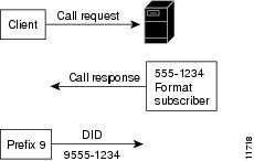
For example, if the remote peer dialed 5557659876, and the ppp bap number command had the default number 5557659912, the local router would respond "3 | 912." In the response, a vertical bar ( | ) is used to divide the number of digits to change from the number sequence to use instead. In the "3 | 912" response, the local router instructs the calling interface to replace the right-most three digits with "912" for BAP.This command is used by the client side for dialing instructions when communicating with the server. Use the prefix keyword on the Always On/Dynamic ISDN (AO/DI) client side to specify what will precede any number dialed to a multilink peer. For example, the client issues a call request to the server whereby the server issues a call response that includes the dialing number the client should use and the format this number should be in (national or subscriber). The client then dials the number supplied by the server, preceded by any prefix information contained in the ppp bap number prefix command. Figure 3 shows an overview about the information exchange between the client and the server.
Figure 3 Client and Server Response Sequence
Use the format keyword on the AO/DI server side to specify how many digits should be returned by BAP. BAP will return the numbers based on either a national or subscriber format. The value that is returned is preceded by the prefix before dialing occurs. For example, if the format national keywords are configured, then the national format (which is equivalent to ten digits) is returned by BAP (during BAP negotiation) from the server.
Note
Examples
In the following example, the AO/DI client uses a ppp bap prefix value of 9, which indicates that the dialed number of 5551234 will be preceded by a 9. The number that is actually dialed is 95551234. The AO/DI server uses a subscriber format, which indicates that when the client asks the server for the numbers to dial, BAP will return seven digits.
Client Router
interface dialer1ppp bap number prefix 9Server Router
interface dialer1ppp bap number format subscriberppp bap number default 5555678In the following example, the AO/DI client uses a ppp bap prefix value of 1, which indicates that the dialed number of 5551234 will be preceded by a 1. The number that is actually dialed is 19195555678 because the server is using a national format, and BAP therefore, returns ten digits.
Client Router
interface dialer1ppp bap number prefix 1Server Router
interface dialer1ppp bap number format nationalppp bap number default 9195555678The following example configures a physical interface with both a default number and a secondary number:
interface bri 0ip unnumbered ethernet 0dialer load-threshold 10 eitherdialer map ip 172.21.13.101 name bap-peer 14085778899encapsulation pppppp multilink bapppp bap call requestppp bap callback acceptno ppp bap call acceptno ppp bap drop acceptppp bap pending timeout 30ppp bap number default 5664567ppp bap number secondary 5664568Related Commands
Enables PPP BAP callback and set callback parameters.
Displays the configuration settings and run-time status for a multilink bundle.
ppp bap timeout
To specify nondefault timeout values for PPP Bandwidth Allocation Protocol (BAP) pending actions and responses, use the ppp bap timeout command in interface configuration mode. To reset the response timeout to the default value, or to remove a pending timeout entirely, use the no form of this command.
ppp bap timeout {pending seconds | response seconds}
no ppp bap timeout {pending | response}
Syntax Description
Defaults
Enabled
pending: 20 seconds
response: 3 seconds
Command Modes
Interface configuration
Command History
Usage Guidelines
The no ppp bap timeout response command resets the timer to the default value.The no ppp bap timeout pending command removes the pending-action timeout entirely (in compliance with the BAP specification).
Examples
The following example configures BAP to wait 45 seconds before timing out pending actions:
interface dialer 1ip unnumbered ethernet 0encapsulation pppppp multilink bapppp bap call acceptppp bap link types isdn analogdialer load threshold 30ppp bap timeout pending 45Related Commands
ppp bridge appletalk
To enable half-bridging of AppleTalk packets across a serial interface, use the ppp bridge appletalk command in interface configuration mode. To disable AppleTalk packet half-bridging, use the no form of this command.
ppp bridge appletalk
no ppp bridge appletalk
Syntax Description
This command has no arguments or keywords.
Defaults
Command is disabled.
Command Modes
Interface configuration
Command History
Usage Guidelines
When you configure a serial or ISDN interface for half-bridging, you configure it to function as a node on an Ethernet subnetwork. It communicates with a bridge on the subnetwork by sending and receiving bridge packets. The serial or ISDN interface converts bridge packets to routed packets and forwards them, as needed.
The serial interface must be configured with an AppleTalk address for communication on the Ethernet subnetwork, and the AppleTalk address must have the same AppleTalk cable range as the bridge.
You cannot configure a serial interface for both half-bridging and for transparent bridging. No more than one half-bridge should be on any subnetwork.
Examples
The following example configures serial interface 0 for half-bridging of AppleTalk. The remote bridge and other Ethernet nodes must be on the same network.
interface serial 0ppp bridge appletalkappletalk cable-range 301-301appletalk zone remote-lanRelated Commands
ppp bridge ip
To enable half-bridging of IP packets across a serial interface, use the ppp bridge ip command in interface configuration mode. To disable IP packet half-bridging, use the no form of this command.
ppp bridge ip
no ppp bridge ip
Syntax Description
This command has no arguments or keywords.
Defaults
Command is disabled.
Command Modes
Interface configuration
Command History
Usage Guidelines
When you configure a serial or ISDN interface for half-bridging, you configure it to function as a node on an Ethernet subnetwork. It communicates with a bridge on the subnetwork by sending and receiving bridge packets. The serial interface converts bridge packets to routed packets and forwards them, as needed.
The interface must be configured with an IP address for communication on the Ethernet subnetwork, and the IP address must be on the same subnetwork as the bridge.
You cannot configure a serial interface for both half-bridging and for transparent bridging.
No more than one half-bridge should be on any subnetwork.
Examples
The following example configures serial interface 0 for half-bridging of IP. The remote bridge and other Ethernet nodes must be on the same subnetwork.
interface serial 0ip address 172.19.5.8ppp bridge ipRelated Commands
ppp bridge ipx
To enable half-bridging of Internetwork Packet Exchange (IPX) packets across a serial interface, use the ppp bridge ipx command in interface configuration mode. To return to the default Novell Ethernet_802.3 encapsulation, use the no form of this command.
ppp bridge ipx [novell-ether | arpa | sap | snap]
no ppp bridge ipx
Syntax Description
Defaults
The default encapsulation is novell-ether.
Command Modes
Interface configuration
Command History
Usage Guidelines
When you configure a serial interface for half-bridging, you configure it to function as a node on an Ethernet subnetwork. It communicates with a bridge on the subnetwork by sending and receiving bridge packets. The serial interface converts bridge packets to routed packets and forwards them, as needed.
The serial interface must be configured with an IPX address for communication on the Ethernet subnetwork, and the IPX address must be on the same subnetwork as the bridge.
You cannot configure a serial interface for both half-bridging and for transparent bridging.
No more than one half-bridge should be on any subnetwork.
Examples
The following example configures serial interface 0 for half-bridging of IPX. The remote bridge and other Ethernet nodes must be on the same subnetwork.
interface serial 0ppp bridge ipxipx network 1800Related Commands
ppp callback (DDR)
To enable a dialer interface to function either as a callback client that requests callback or as a callback server that accepts callback requests, use the ppp callback command in interface configuration mode. To disable a function, use the no form of this command.
ppp callback {accept | permit | request}
no ppp callback
Syntax Description
Defaults
Callback requests are neither accepted nor requested.
Command Modes
Interface configuration
Command History
Usage Guidelines
An interface can request PPP callback only if the interface is configured for PPP authentication with Challenge Handshake Authentication Protocol (CHAP) or Password Authentication Protocol (PAP).
Examples
The following example configures a previously defined dialer interface to accept PPP callback requests:
ppp callback acceptRelated Commands
ppp callback (PPP client)
To enable a PPP client to dial in to an asynchronous interface and request a callback, use the ppp callback command in interface configuration mode. To disable callback acceptance, use the no form of this command.
ppp callback {accept | initiate}
no ppp callback
Syntax Description
accept
Accept callback requests from RFC 1570-compliant PPP clients on the interface.
initiate
Initiate a callback to non-RFC 1570-compliant PPP clients dialing in to an asynchronous interface.
Defaults
Callback requests are not accepted on asynchronous interfaces.
Command Modes
Interface configuration
Command History
Usage Guidelines
PPP callback can be initiated only if the interface is configured for authentication using CHAP or PAP.
Examples
The following example accepts a callback request from an RFC-compliant PPP client:
ppp callback acceptThe following example accepts a callback request from a non-RFC-compliant PPP client:
ppp callback initiateRelated Commands
ppp caller name
To set the caller option when no Calling Line Identification (CLID) is available, use the ppp caller name command in interface configuration mode. To remove the name, use the no form of this command.
ppp caller name name
no ppp caller name name
Syntax Description
Defaults
Command is disabled by default.
Command Modes
Interface configuration
Command History
Usage Guidelines
This command sets the username used when the CLID is not available. This username is used only in the case where the ppp dnis command is configured and the CLID is not available.
Examples
The following example shows how to configure a call to user1:
interface Serial0:15description "PRI D channel"ip unnumbered Loopback0encapsulation pppno keepalivedialer pool-member 1 max-link 1isdn switch-type primary-net5isdn incoming-voice modemno fair-queueno cdp enableppp caller name user1ppp authentication pap chap callin USERS&TUNNELSppp chap hostname oshRelated Commands
ppp dnis
To configure a set of dialed number identification service (DNIS) numbers to check an incoming call against to automatically authenticate and authorize a user, use the ppp dnis command in interface configuration mode. To remove the numbers, use the no form of this command.
ppp dnis DNIS-numbers
no ppp dnis DNIS-numbers
Syntax Description
Defaults
This command is disabled by default.
Command Modes
Interface configuration
Command History
Usage Guidelines
This command enables a method of authenticating and authorizing a user based on the DNIS. The DNIS is the number dialed by the user. If the dialed number for this session matches one of the numbers configured in the ppp dnis command, the user is automatically authenticated and authorized for the session. Any other configured PPP authentication is not performed. In the case of DNIS authentication, the Calling Line Identification (CLID) is used as the username. If the CLID is unavailable, the username is the name configured with the ppp caller name command. If neither the CLID nor a caller name is configured, the username will automatically be set to "no-clid."
Examples
The following example shows how to set the DNIS for a call:
interface Serial0:15description "PRI D channel"ip unnumbered Loopback0encapsulation pppno keepalivedialer pool-member 1 max-link 1isdn switch-type primary-net5isdn incoming-voice modemno fair-queueno cdp enableppp dnis 13693 132ppp authentication pap chap callin USERS&TUNNELSppp chap hostname oshRelated Commands
ppp encrypt mppe
To enable Microsoft Point-to-Point Encryption (MPPE) on the virtual template, use the ppp encrypt mppe command in interface configuration mode. To disable MPPE, use the no form of this command.
ppp encrypt mppe {auto | 40 | 128} [passive | required] [stateful]
no ppp encrypt mppe
Syntax Description
Command Default
MPPE encryption is disabled.
Command Modes
Interface configuration
Command History
12.0(5)XE5
This command was introduced.
12.1(5)T
This command was integrated into Cisco IOS Release 12.1(5)T.
Usage Guidelines
To use the ppp encrypt mppe command, PPP encapsulation must be enabled.
Note
The auto keyword is offered only on 128-bit images.
All of the configurable MPPE options must be identical on both tunnel endpoints.
Note
Examples
The following example shows a virtual template configured to perform 40-bit MPPE encryption:
interface Virtual-Template1ip unnumbered FastEthernet0/0no ip directed-broadcastip mroute-cacheno keepaliveppp encrypt mppe 40ppp authentication ms-chapRelated Commands
ppp ipcp
To configure PPP IP Control Protocol (IPCP) features such as the ability to provide primary and secondary Domain Name Server (DNS) and Windows Internet Naming Service (WINS) server addresses, and the ability to accept any address requested by a peer, use the ppp ipcp command in template or interface configuration mode. To disable a ppp ipcp feature, use the no form of this command.
ppp ipcp {accept-address} | {dns {reject | accept | primary-ip-address [secondary-ip-address] [accept]} | {ignore-map} | {username unique} | {wins {reject | accept | primary-ip-address [secondary-ip-address] [accept]}}}
no ppp ipcp {accept-address} | {dns {reject | accept | primary-ip-address [secondary-ip-address] [accept]} | {ignore-map} | {username unique} | {wins {reject | accept | primary-ip-address [secondary-ip-address] [accept]}}}
Syntax Description
Defaults
No servers are configured, and no address request is made.
Command Modes
Template configuration
interface configurationCommand History
12.0(6)T
This command was introduced.
12.1(5)T
The reject and accept keywords were added.
Usage Guidelines
To negate a command, the dns, wins, accept-address, ignore-map, and username unique keywords can be entered without addresses or other options. See the examples for clarification.
Examples
The following examples show use of the ppp ipcp command:
ppp ipcp accept-addressppp ipcp dns 10.1.1.3ppp ipcp dns 10.1.1.3 10.1.1.4ppp ipcp dns 10.1.1.1 10.1.1.2 acceptppp ipcp dns acceptppp ipcp dns rejectppp ipcp ignore-mapppp ipcp username uniqueppp ipcp wins 10.1.1.1 10.1.1.2ppp ipcp wins acceptThe following examples show how to use the no form of the ppp ipcp command:
no ppp ipcp wins 10.1.1.1 10.1.1.2no ppp ipcp winsno ppp ipcp ignore-mapRelated Commands
ppp iphc max-header
To set the maximum size of the largest IP header that may be compressed when configuring Internet Protocol Header Compression (IPHC) control options over PPP, use the ppp iphc max-header command in interface configuration mode. To change the configuration, use the no form of this command.
ppp iphc max-header bytes
no ppp iphc max-header bytes
Syntax Description
bytes
Maximum size, in bytes, of the largest IP header that may be compressed. The range is from 60 to 168 bytes, and the default is 168 bytes.
Defaults
168 bytes
Command Modes
Interface configuration
Command History
Usage Guidelines
There are two types of IP header compression used over PPP: Van Jacobsen header compression defined in RFC 1332 and enabled with the ip tcp header-compression command, and IPHC defined in RFC 2509 and enabled with the ip rtp header-compression command. The ppp iphc set of commands controls parameters that pertain to the form of IPHC described in RFC 2509.
The IPHC specification allows low speed links to run more efficiently by reducing the size of the IP headers as transmitted on the link. IPHC supports compressed Real-Time Transport Protocol (cRTP), compressed User Datagram Protocol (cUDP), and compressed Transaction Control Protocol (cTCP).
An IPHC-enabled interface sends only changes to the header instead of sending the entire header with every packet. At the beginning of a transmission, the transmitting end (the compressor) sends a full header packet to the receiving end (the decompressor). After the initial packet is sent, the compressor sends all other packets with headers that contain only the differences between them and the original full header. The decompressor maintains a copy of the original full header and reconstructs all the other packet headers by adding the changes to them.
The header data that is different with each packet is referred to as the session state, and is identified by a session ID or connection ID.
When the decompressor receives a compressed packet, it reconstructs the packet header by adding the difference to the saved uncompressed header. Typically, IPHC enables the header to be compressed to two bytes (four bytes if UDP checksums are used).
The following fields in a packet header usually remain the same throughout a transmission:
•
•
•
The following fields in a packet header usually change during a transmission:
•
•
•
•
•
Examples
The following example shows how to change the maximum size of the largest IP header that may be compressed from the default of 168 bytes to 114 bytes:
interface Multilink1ip address 10.100.253.1 255.255.255.0no ip directed-broadcastno ip route-cacheip tcp header-compression iphc-formatno ip mroute-cachefair-queue 64 256 1000no cdp enableppp multilinkppp multilink fragment-delay 20ppp multilink interleavemultilink-group 1ip rtp header-compression iphc-formatip rtp priority 16384 50 64ppp iphc max-header 114ppp iphc max-time 10ppp iphc max-period 512Related Commands
ppp iphc max-period
To set the maximum number of compressed packets that can be sent before a full header when configuring Internet Protocol Header Compression (IPHC) control options over PPP, use the ppp iphc max-period command in interface configuration mode. To change the configuration, use the no form of this command.
ppp iphc max-period packets
no ppp iphc max-period packets
Syntax Description
packets
Maximum number of compressed packets that can be sent before a full header. The range is from 1 to 65,535 packets, and the default is 256 packets.
Defaults
256 packets
Command Modes
Interface configuration
Command History
Usage Guidelines
There are two types of IP header compression used over PPP: Van Jacobsen header compression, which is defined in RFC 1332, and a newer compression type described in RFC 2509. The ppp iphc set of commands controls parameters that pertain to the form of IPHC described in RFC 2509.
The IPHC specification allows low speed links to run more efficiently when IP headers are extremely large. IPHC supports compressed Real-Time Transport Protocol (cRTP), compressed User Datagram Protocol (cUDP), and compressed Transaction Control Protocol (cTCP).
An IPHC-enabled interface sends only changes to the header instead of sending the entire header with every packet. At the beginning of a transmission, the transmitting end (the compressor) sends a full header packet to the receiving end (the decompressor). After the initial packet is sent, the compressor sends all other packets with headers that contain only the differences between them and the original full header. The decompressor maintains a copy of the original full header and reconstructs all the other packet headers by adding the changes to them.
The header data that is different with each packet is referred to as the session state, and is identified by a session ID or connection ID.
When the decompressor receives a compressed packet, it reconstructs the packet header by adding the difference to the saved uncompressed header. Typically, IPHC enables the header to be compressed to two bytes (four bytes if UDP checksums are used).
The following fields in a packet header usually remain the same throughout a transmission:
•
•
•
The following fields in a packet header usually change during a transmission:
•
•
•
•
•
The ppp iphc max-period command is specifically related to an IPHC frame format known as compressed_non_TCP. The recovery of lost compressed_non_TCP frames on lossy links is much improved by allowing more full headers to flow and by configuring less compression.
Examples
The following example shows how to increase the maximum number of compressed packets that can be sent before a full header from 256 to 512 packets when configuring IPHC control options over PPP:
interface Multilink1ip address 10.100.253.1 255.255.255.0no ip directed-broadcastno ip route-cacheip tcp header-compression iphc-formatno ip mroute-cachefair-queue 64 256 1000no cdp enableppp multilinkppp multilink fragment-delay 20ppp multilink interleavemultilink-group 1ip rtp header-compression iphc-formatip rtp priority 16384 50 64ppp iphc max-header 114ppp iphc max-time 10ppp iphc max-period 512Related Commands
ppp iphc max-time
To set the maximum time allowed between full headers when configuring Internet Protocol Header Compression (IPHC) control options over PPP, use the ppp iphc max-time command in interface configuration mode. To change the configuration, use the no form of this command.
ppp iphc max-time seconds
no ppp iphc max-time seconds
Syntax Description
seconds
Maximum time, in seconds, allowed between full headers. The range is from 1 to 255 seconds, and the default is 5 seconds.
Defaults
5 seconds
Command Modes
Interface configuration
Command History
Usage Guidelines
There are two forms of IP header compression used over PPP: Van Jacobsen header compression, which is defined in RFC 1332, and a newer form of compression described in RFC 2509. The ppp iphc set of commands controls parameters that pertain to the form of IPHC described in RFC 2509.
The IPHC specification allows low speed links to run more efficiently by reducing the size of IP headers as transmitted on the link. IPHC supports compressed Real-Time Transport Protocol (cRTP), compressed User Datagram Protocol (cUDP), and compressed Transaction Control Protocol (cTCP).
An IPHC-enabled interface sends only changes to the header instead of sending the entire header with every packet. At the beginning of a transmission, the transmitting end (the compressor) sends a full header packet to the receiving end (the decompressor). After the initial packet is sent, the compressor sends all other packets with headers that contain only the differences between them and the original full header. The decompressor maintains a copy of the original full header and reconstructs all the other packet headers by adding the changes to them.
The header data that is different with each packet is referred to as the session state, and is identified by a session ID or connection ID.
When the decompressor receives a compressed packet, it reconstructs the packet header by adding the difference to the saved uncompressed header. Typically, IPHC enables the header to be compressed to two bytes (four bytes if UDP checksums are used).
The following fields in a packet header usually remain the same throughout a transmission:
•
•
•
The following fields in a packet header usually change during a transmission:
•
•
•
•
•
The ppp iphc max-time command is specifically related to an IPHC frame format known as compressed_non_TCP. The recovery of lost compressed_non_TCP frames on lossy links is much improved by allowing more full headers to flow and by configuring less compression.
Examples
The following example shows how to change the number of compressed packets that can be sent before a full header from the default 5 seconds to 10 seconds:
interface Multilink1ip address 10.100.253.1 255.255.255.0no ip directed-broadcastno ip route-cacheip tcp header-compression iphc-formatno ip mroute-cachefair-queue 64 256 1000no cdp enableppp multilinkppp multilink fragment-delay 20ppp multilink interleavemultilink-group 1ip rtp header-compression iphc-formatip rtp priority 16384 50 64ppp iphc max-header 114ppp iphc max-time 10ppp iphc max-period 512Related Commands
ppp lcp delay
To set a delay before initiating link control protocol (LCP) negotiations after a link connects, use the ppp lcp delay command in interface configuration mode. To remove the delay, use the no form of this command.
ppp lcp delay seconds
no ppp lcp delay seconds
Syntax Description
Defaults
Default is 2 seconds.
Command Modes
Interface configuration
Command History
Usage Guidelines
The delay setting is for those situations in which it is desired that PPP does not initiate LCP negotiations with a peer system after the link has come up, but instead waits for a short amount of time to let the peer send the first packet.
The LCP delay is applied only to incoming connections. PPP does not delay for outbound connections or connections where PPP cannot determine a direction.
Examples
The following example sets the delay to 4 seconds:
ppp lcp delay 4ppp lcp fast-start
To allow a PPP interface to respond immediately to incoming packets once a connection is established, use the ppp lcp fast-start command in interface configuration mode. To specify that PPP delay before responding, use the no form of this command.
ppp lcp fast-start
no ppp lcp fast-start
Syntax Description
This command has no arguments or keywords.
Defaults
Command is enabled by default.
Command Modes
Interface configuration
Command History
Usage Guidelines
Some systems, typically those with external modems, may have problems with slow or electrically noisy hardware. If the no ppp lcp fast-start command is specified, PPP starts a debounce timer and waits for it to expire before attempting to communicate with the peer system, thereby reducing the probability of a false start on the interface.
If the no ppp lcp fast-start command is not specified, PPP will not use a debounce timer and will respond immediately to incoming packets once a connection is made.
The default fast start enabled state should not be disabled unless there is a problem with slow or electronically noisy hardware. This setting prevents PPP from waiting for a debounce timer to expire before responding to inbound frames.
Examples
The following example disables fast start:
no ppp lcp fast-startppp link reorders
To set an advisory flag that indicates the serial interface may receive packets in a different order than a peer system sent them, use the ppp link reorders command in interface configuration mode. To turn this flag off, use the no form of this command.
ppp link reorders
no ppp link reorders
Syntax Description
This command has no arguments or keywords.
Defaults
Command is disabled.
Command Modes
Interface configuration
Command History
Usage Guidelines
The ppp link reorders command indicates that a link can receive packets in a different order than the peer system sent them. This situation can be encountered with PPP tunneling mechanisms such as Layer 2 Forwarding (L2F) and the Layer 2 Transport Protocol (L2TP) that do not always enforce strictly serial delivery of frames from source to final destination. Such links can pose problems for PPP features that depend upon in-order delivery of packets, such as compression, encryption, network header compression, and Multilink PPP.
Setting this option allows some PPP systems to compensate to an extent for the nonserial delivery of packets, although this compensation can incur a performance penalty. It is not normally necessary to configure the ppp link reorders command. PPP automatically recognizes that the condition exists for Virtual Private Network (VPN) tunnels, and the misdelivery situation will not occur on normal serial interfaces.
Examples
The following example sets the ppp link reorders command advisory flag:
ppp link reordersppp loopback ignore
To disable PPP loopback detection, use the ppp loopback ignore command in interface configuration mode. To reenable PPP loopback detection (the default condition), use the no form of this command.
ppp loopback ignore
no ppp loopback ignore
Syntax Description
This command has no arguments or keywords.
Defaults
Loopback detection is enabled.
Command Modes
Interface configuration
Command History
11.3
This command was introduced as ppp ignore-loopback.
12.2(5)T
The ppp loopback ignore command replaced the ppp ignore-loopback command.
Usage Guidelines
A circuit loopback normally indicates faulty external switching equipment or wiring errors. The PPP protocol includes a mechanism that detects when a circuit is looped back, that is, when the circuit is fed back upon itself such that the router is reading its own output on that link. A first phase of loopback detection occurs during Link Control Protocol (LCP) negotiation when the circuit is being established. A loopback condition that occurs after the connection is made (after LCP negotiation) can be detected if link keepalives are enabled. If keepalives are disabled on the link, the second phase of loopback detection is not available.
The normal operation (default) is for PPP to check for a loopback condition and terminate the connection when a loopback is detected. There are, however, some situations where it is necessary to disable loopback detection, such as during certain testing situations, or when software detects problematic peers that do not implement the PPP protocol correctly. The ppp loopback ignore command disables normal operation; the no ppp loopback ignore command restores normal operation.
Note
Examples
The following example shows PPP loopback detection being disabled:
interface Serial0:15description "PRI D channel"ip unnumbered Loopback0encapsulation pppppp loopback ignoreRelated Commands
keepalive
Configures a keepalive packet that is sent at a certain time interval, and for a certain number of retries if there is no response, to keep an interface active.
ppp max-bad-auth
To configure a point-to-point interface not to reset itself immediately after an authentication failure but instead to allow a specified number of authentication retries, use the ppp max-bad-auth command in interface configuration mode. To reset to the default of immediate reset, use the no form of this command.
ppp max-bad-auth retries
no ppp max-bad-auth
Syntax Description
Defaults
The default is 0.
Command Modes
Interface configuration
Command History
Usage Guidelines
This command applies to any serial interface (asynchronous serial, synchronous serial, or ISDN) on which PPP encapsulation is enabled.
Examples
The following example sets BRI interface 0 to allow two additional retries after an initial authentication failure (for a total of three failed authentication attempts):
interface bri 0encapsulation pppppp authentication chapppp max-bad-auth 3Related Commands
ppp mru match
To trigger Link Control Protocol (LCP) renegotiation on a maximum receive unit (MRU) mismatch on a system acting as an L2TP network server (LNS) and thereby enforce strict matching, use the ppp mru match command in interface configuration mode. To remove this setting, use the no form of this command.
ppp mru match
no ppp mru match
Syntax Description
This command has no arguments or keywords.
Defaults
This command is disabled by default.
Command Modes
Interface configuration
Command History
Usage Guidelines
This command is configured only on virtual template interfaces.
By default, the LNS does not enforce matching of the MRU value advertised by the LAC with the MRU value that the LNS would advertise. Use the ppp mru match command to enforce strict matching of the MRU that is advertised by the Layer 2 Tunneling Protocol (L2TP) access concentrator (LAC) with the maximum transmission unit (MTU) of the relevant virtual template interface on the LNS. A mismatch can occur because the effective MRU size for a virtual access interface is not necessarily limited to the MTU size.
This command can be useful to inform the client PPP stack of the true MRU, when that PPP implementation is capable of adapting its MTU based on LCP MRU negotiation.
Examples
The following example shows LCP renegotiation being triggered on an MRU mismatch:
interface Virtual-Template1mtu 1454ppp mru matchip unnumbered GigabitEthernet0/1no keepalivepeer default ip address pool mypoolppp authentication papRelated Commands
ppp ms-chap refuse
To refuse Microsoft Challenge Handshake Authentication Protocol (MS-CHAP) authentication from peers requesting it, use the ppp ms-chap refuse command in interface configuration mode. To allow MS-CHAP authentication, use the no form of this command.
ppp ms-chap refuse [callin]
no ppp ms-chap refuse [callin]
Syntax Description
Defaults
This command is disabled by default.
Command Modes
Interface configuration
Command History
Usage Guidelines
This command specifies that MS-CHAP authentication is disabled for all calls, meaning that all attempts by the peer to force the user to authenticate using MS-CHAP will be refused. If the callin keyword is used, MS-CHAP authentication is disabled for incoming calls from the peer, but will still be performed on outgoing calls to the peer.
If outbound Password Authentication Protocol (PAP) has been enabled (using the ppp pap sent-username command), PAP will be suggested as the authentication method in the refusal packet.
Examples
The following example shows how to disable MS-CHAP authentication if a peer calls in requesting MS-CHAP authentication. The method of encapsulation on interface ISDN BRI number 0 is PPP.
interface bri 0encapsulation pppppp ms-chap refuseRelated Commands
ppp ms-chap-v2 refuse
To refuse Microsoft Challenge Handshake Authentication Protocol (MS-CHAP) version 2 authentication from peers requesting it, use the ppp ms-chap-v2 refuse command in interface configuration mode. To allow MS-CHAP version 2 authentication, use the no form of this command.
ppp ms-chap-v2 refuse [callin]
no ppp ms-chap-v2 refuse [callin]
Syntax Description
Defaults
This command is disabled by default.
Command Modes
Interface configuration
Command History
Usage Guidelines
This command specifies that MS-CHAP version 2 authentication is disabled for all calls, meaning that all attempts by the peer to force the user to authenticate using MS-CHAP version 2 will be refused. If the callin keyword is used, MS-CHAP version 2 authentication is disabled for incoming calls from the peer, but will still be performed on outgoing calls to the peer.
If outbound Password Authentication Protocol (PAP) has been enabled (using the ppp pap sent-username command), PAP will be suggested as the authentication method in the refusal packet.
Examples
The following example shows how to disable MS-CHAP version 2 authentication if a peer calls in requesting MS-CHAP version 2 authentication. The method of encapsulation on interface ISDN BRI number 0 is PPP.
interface bri 0encapsulation pppppp ms-chap-v2 refuseRelated Commands
ppp mtu adaptive
To define autonegotiation of the MTU size for PPP based on the peer or proxy maximum receive unit (MRU), use the ppp mtu adaptive command in interface configuration mode. To return to the default setting, use the no form of this command.
ppp mtu adaptive [proxy]
no ppp mtu adaptive [proxy]
Syntax Description
Defaults
This command is disabled by default.
Command Modes
Interface configuration
Command History
Usage Guidelines
By default, the Cisco IOS software will not adapt the interface MTU to the peer or proxy MRU.
Use this command on interfaces where a number of peers with different MRU settings may connect. In Cisco IOS Release 12.2(7) and later releases, this command is configured on only virtual template interfaces. In Cisco IOS Release 12.3(14)T and later releases, the ppp mtu adaptive command without the proxy keyword can be configured on serial interfaces.
The proxy keyword is not typically required. It is used only as a workaround when the client PPP stack is incapable of correctly advertising its MRU requirements.
Examples
The following example defines autonegotiation of the MTU size on a virtual template:
interface Virtual-Template1no ip addressno logging event link-statusno snmp trap link-statusppp mtu adaptiveppp authentication chap callinRelated Commands
ppp multilink
To enable Multilink PPP (MLP) on an interface and, optionally, to enable Bandwidth Allocation Control Protocol (BACP) and Bandwidth Allocation Protocol (BAP) for dynamic bandwidth allocation, use the ppp multilink command in interface configuration mode. To disable Multilink PPP or, optionally, to disable only dynamic bandwidth allocation, use the no form of this command.
ppp multilink [bap]
no ppp multilink [bap [required]]
Syntax Description
Defaults
Command is disabled. When BACP is enabled, the defaults are to accept calls and to set the timeout pending at 30 seconds.
Command Modes
Interface configuration
Command History
Usage Guidelines
This command applies only to interfaces that use PPP encapsulation.
MLP and PPP reliable links do not work together.
When the ppp multilink command is used, the first channel will negotiate the appropriate Network Control Protocol (NCP) layers (such as the IP Control Protocol and IPX Control Protocol), but subsequent links will negotiate only the link control protocol and MLP. NCP layers do not get negotiated on these links, and it is normal to see these layers in a closed state.
This command with the bap keyword must be used before configuring any ppp bap commands and options. If the bap required option is configured and a reject of the options is received, the multilink bundle is torn down.
The no form of this command without the bap keyword disables both MLP and BACP on the interface.
The dialer load-threshold command enables a rotary group to bring up additional links and to add them to a multilink bundle.
Before Cisco IOS Release 11.1, the dialer-load threshold 1 command kept a multilink bundle of any number of links connected indefinitely and the dialer-load threshold 2 command kept a multilink bundle of two links connected indefinitely. If you want a multilink bundle to be connected indefinitely, you must set a very high idle timer.
Examples
The following partial example configures a dialer for Multilink PPP; it does not show the configuration of the physical interfaces:
interface Dialer0ip address 10.0.0.2 255.0.0.0encapsulation pppdialer in-banddialer idle-timeout 500dialer map ip 10.0.0.1 name atlanta broadcast 81012345678901dialer load-threshold 30 eitherdialer-group 1ppp authentication chapppp multilinkRelated Commands
ppp multilink endpoint
To override or change the default endpoint discriminator the system uses when negotiating the use of Multilink PPP (MLP) with the peer, use the ppp multilink endpoint command in interface configuration mode. To restore the default endpoint discriminator, use the no form of this command.
ppp multilink endpoint {hostname | ip ip-address | mac lan-interface | none |
phone telephone-number | string char-string}no ppp multilink endpoint
Syntax Description
Defaults
The default endpoint discriminator is the globally configured host name, or the Challenge Handshake Authentication Protocol (CHAP) host name or Password Authentication Protocol (PAP) sent-username configured on the interface. See the "Usage Guidelines" for additional information.
Command Modes
Interface configuration
Command History
Usage Guidelines
By default, PPP uses the same string for the endpoint discriminator that it would provide for authentication to negotiate use of MLP with the peer. The string (username) is configured for the interface with the ppp chap hostname or ppp pap sent-username command, or defaults to the globally configured host name (or stack group name, if the interface is a Stack Group Bidding Protocol, or SGBP, group member). The keywords supplied with the ppp multilink endpoint command allow a different endpoint discriminator to be defined. You can reset the default condition by entering the no ppp multilink endpoint command.
The difference between the no ppp multilink endpoint command and the ppp multilink endpoint hostname command is that for the first command, MLP supplies the name used for authentication (which may or may not be the router host name), and the second command always uses the router host name, regardless of any local authentication configuration.
Both the hostname and string keywords use the local endpoint class, the differences between them being that the string keyword allows you to enter a value, while the hostname keyword uses the configured (default) host name.
Note
Refer to RFC 1990 for more information about MLP and the endpoint discriminator option.
Examples
The following partial example changes the endpoint discriminator from the CHAP host named group 1 to IP address 10.1.1.4:
...interface Dialer0ip address 10.1.1.4 255.255.255.0encapsulation pppdialer remote-name R-namedialer string 23456dialer pool 1dialer-group 1ppp chap hostname group 1ppp multilink endpoint ip 10.1.1.4...Related Commands
ppp multilink fragment delay
To specify a maximum size in units of time for packet fragments on a Multilink PPP (MLP) bundle, use the ppp multilink fragment delay command in interface configuration mode. To reset the maximum delay to the default value, use the no form of this command.
ppp multilink fragment delay delay-max
no ppp multilink fragment delay
Syntax Description
delay-max
Maximum amount of time, in milliseconds, that should be required to transmit a fragment. The range is from 1 to 1000 milliseconds.
Defaults
No default behavior or values are set, but MLP requires a time delay value and will assume a value 30 milliseconds.
Command Modes
Interface configuration
Command History
11.3
This command was introduced as ppp multilink fragment-delay.
12.2
The command was changed to ppp multilink fragment delay.
Usage Guidelines
By default, MLP has no fragment size constraint and packets are divided into a number of fragments whose number is based on the number of links in the bundle. The size of any fragment is unconstrained, but the maximum number of fragments is constrained by the number of links. If interleaving is enabled, or if the bundle contains links that have differing bandwidths, or if a fragment delay is explicitly configured with the ppp multilink fragment delay command, then MLP uses a different fragmentation algorithm. In this mode, the number of fragments is unconstrained, but the size of each fragment is limited to the fragment delay value, or 30 milliseconds if the fragment delay has not been configured.
The ppp multilink fragment delay command is useful when packets are interleaved and traffic characteristics such as delay, jitter, and load balancing must be tightly controlled.
The ppp multilink fragment delay command applies only to interfaces that can configure a bundle interface, such as virtual templates, dialer interfaces, and ISDN BRI or PRI interfaces.
The value assigned to the delay-max argument is scaled by the speed at which a link can convert the time value into a byte value. If a bundle has multiple links with varying speeds, the absolute size of a fragment will differ for each link.
MLP chooses a fragment size on the basis of the maximum delay allowed. If real-time traffic requires a certain maximum bound on delay, using this command to set that maximum time can ensure that a real-time packet will get interleaved within the fragments of a large packet.
Examples
The following example requires a voice interface to have a maximum bound on delay of 20 milliseconds:
ppp multilink fragment delay 20Related Commands
ppp multilink fragment disable
To disable packet fragmentation, use the ppp multilink fragment disable command in interface configuration mode. To enable fragmentation, use the no form of this command.
ppp multilink fragment disable
no ppp multilink fragment disable
Syntax Description
This command has no arguments or keywords.
Defaults
Fragmentation is enabled.
Command Modes
Interface configuration
Command History
Usage Guidelines
Disable multilink fragmentation using the ppp multilink fragment disable command if fragmentation causes performance degradation. Performance degradation due to multilink fragmentation has been observed with asynchronous member links. This command does not disable fragmentation completely. When fragmentation is mandatory (e. g. when a bundle level packet exceeds the member link MTU size), it will still be performed.
Examples
The following example disables packet fragmentation:
ppp multilink fragment disableRelated Commands
ppp multilink fragment delay
Specifies a maximum size, in units of time, for packet fragments on an MLP bundle.
ppp multilink interleave
Enables MLP interleaving.
ppp multilink fragmentation
The ppp multilink fragmentation command is replaced by the ppp multilink fragment disable command. See the description of the ppp multilink fragment disable command for more information.
ppp multilink fragment maximum
To set the maximum number of fragments a packet will be segmented into before being sent over the bundle, use the ppp multilink fragment maximum command in interface configuration mode. To reset fragmentation to the default value, use the no form of this command.
ppp multilink fragment maximum fragments
no ppp multilink fragment maximum
Syntax Description
Defaults
16 fragments
Command Modes
Interface configuration
Command History
Usage Guidelines
Use the ppp multilink fragment maximum command to control the number of fragments into which a PPP frame may be fragmented. The ppp multilink fragment maximum command has been used to disable fragmentation entirely by setting the number of fragments to 1. This setting is better accomplished using the ppp multilink fragment disable command.
The limit set using the ppp multilink fragment maximum command applies only when Multilink PPP (MLP) is fragmenting packets in a mode where it is constraining the number of fragments rather than the size of the fragments. See the description about fragmentation modes in the section "Usage Guidelines" of the ppp multilink fragment delay command for more details.
Examples
The following example uses the ppp multilink fragment maximum command to fragment each frame into no more than four fragments:
ppp multilink fragment maximum 4Related Commands
ppp multilink fragment delay
Specifies a maximum size, in units of time, for packet fragments on an MLP bundle.
ppp multilink fragment disable
Disables packet fragmentation.
ppp multilink group
To restrict a physical link to joining only a designated multilink-group interface, use the ppp multilink group command in interface configuration mode. To remove the restrictions, use the no form of this command.
ppp multilink group group-number
no ppp multilink group
Syntax Description
Defaults
Command is disabled.
Command Modes
Interface configuration
Command History
Usage Guidelines
By default this command is disabled, which means the link can negotiate to join any bundle in the system.
When the ppp multilink group command is configured, the physical link is restricted from joining any but the designated multilink-group interface. If a peer at the other end of the link tries to join a different bundle, the connection is severed. This restriction applies when Multilink PPP (MLP) is negotiated between the local end and the peer system. The link can still come up as a regular PPP interface.
This command is primarily used with the MLP inverse multiplexer described in the "Configuring Media-Independent PPP and Multilink PPP" chapter in the Cisco IOS Dial Technologies Configuration Guide, Release 12.2.
Examples
The following example designates serial interface 1 as part of multilink bundle 1:
interface serial 1encapsulation pppppp multilink group 1ppp multilinkppp authentication chappulse-time 3Related Commands
ppp multilink idle-link
To configure a multilink bundle so that the slowest link enters into receive-only mode when a link is added, use the ppp multilink idle-link command in interface configuration mode. To remove the idle link flag, use the no form of this command.
ppp multilink idle-link
no ppp multilink idle-link
Syntax Description
This command has no arguments or keywords.
Defaults
no ppp multilink idle-link
Command Modes
Interface configuration
Command History
Usage Guidelines
When the idle link flag is enabled, Multilink PPP (MLP) places the slowest link in a bundle into an idle receive-only mode whenever the bundle has more than one link.
This mode is used for the Always On/Dynamic ISDN (AO/DI) feature, where a bundle contains one permanent slow-speed member link, which is on an X.25 circuit contained on an ISDN D channel. As additional and faster links join the MLP bundle, the D channel circuit will be idled and traffic confined to the faster links.
The ppp multilink idle-link command was intended specifically to enable the AO/DI feature. The command will work on any bundle, but normally should not be used outside the AO/DI environment.
Examples
The following example configures the interface (dialer interface 1) to add links to the MLP bundle once the traffic load on the primary link is reached:
interface dialer1ppp multilink idle-linkppp multilink interleave
To enable interleaving of packets among the fragments of larger packets on a Multilink PPP (MLP) bundle, use the ppp multilink interleave command in interface configuration mode. To disable interleaving, use the no form of this command.
ppp multilink interleave
no ppp multilink interleave
Syntax Description
This command has no arguments or keywords.
Defaults
Interleaving is disabled by default.
Command Modes
Interface configuration
Command History
Usage Guidelines
The ppp multilink interleave command applies only to interfaces that can configure a bundle interface, such as virtual templates, dialer interfaces, multilink interfaces, and ISDN BRI or PRI interfaces. For the Versatile Interface Processor (VIP)-enabled Cisco 7500 series routers, this command can be configured using only virtual template interfaces configured for ATM and Frame Relay.
Interleaving works only when the queueing mode on the bundle has been set to fair queueing (all platforms except the VIP-enabled Cisco 7500 series routers) or to Distributed Low Latency Queueing (dLLQ) for the the VIP-enabled Cisco 7500 series routers.
On the VIP-enabled Cisco 7500 series routers, distributed Cisco Express Forwarding (dCEF) must be enabled, and dLLQ configured using the priority command in policy map configuration mode, before using the ppp multilink interleave command.
For all platforms except the VIP-enabled Cisco 7500 series routers, the ppp multilink interleave command should not be set unless weighted fair queueing (WFQ) has been configured using the default fair-queue command.
If interleaving is enabled when fragment delay is not configured, the default delay is 30 milliseconds. The fragment size is derived from that delay, depending on the bandwidths of the links.
Examples
The following example defines a virtual interface template that enables MLP interleaving and a maximum real-time traffic delay of 20 milliseconds, and then applies that virtual template to the MLP bundle:
interface virtual-template 1ip unnumbered ethernet 0ppp multilinkppp multilink interleaveppp multilink fragment delay 20!multilink virtual-template 1The following example shows the configuration of link fragmentation and interleaving (LFI) using MLP running on top of a PPP link over Frame Relay using a virtual template interface:
class-map voipmatch ip precedence 5!class-map businessmatch ip precedence 3!policy-map llq-policyclass voippriority 32class businessbandwidth 32!policy-map shape-llq-policyclass class-defaultshape average 80000 320 320service-policy llq-policy!policy-map input-policyclass voippolice 32000 1500 1500 conform-action transmit exceed-action drop!controller T1 5/1/0framing esflinecode b8zschannel-group 0 timeslots 1-2!interface Serial5/1/0:0no ip addressencapsulation frame-relay!interface Serial5/1/0:0.1 point-to-pointframe-relay interface-dlci 20 ppp Virtual-Template2!interface Virtual-Template2bandwidth 78ip unnumbered Loopback1no keepaliveservice-policy output llq-policyservice-policy input input-policyppp multilinkppp multilink fragment-delay 8ppp multilink interleaveThe following example shows the configuration of LFI using MLP running on top of a PPPoATM link on an ATM interface. This configuration uses a virtual template interface.
class-map voipmatch ip precedence 5!class-map businessmatch ip precedence 3!policy-map llq-policyclass voippriority 32class businessbandwidth 32!policy-map input-policyclass voippolice 32000 1500 1500 conform-action transmit exceed-action drop!interface ATM4/0/0no ip addressno atm ilmi-keepalive!interface ATM4/0/0.1 point-to-pointpvc 0/34abr 100 80protocol ppp Virtual-Template4!interface Virtual-Template4bandwidth 78ip unnumbered Loopback1service-policy output llq-policyservice-policy input input-policyppp multilink!class-map voipmatch ip precedence 5!class-map businessmatch ip precedence 3!policy-map llq-policyclass voippriority 32class businessbandwidth 32!policy-map input-policyclass voippolice 32000 1500 1500 conform-action transmit exceed-action drop!interface ATM4/0/0no ip addressno atm ilmi-keepalive!interface ATM4/0/0.1 point-to-pointpvc 0/34abr 100 80protocol ppp Virtual-Template4!interface Virtual-Template4bandwidth 78ip address 10.0.0.2 255.0.0.0service-policy output llq-policyservice-policy input input-policyppp multilinkppp multilink fragment-delay 8ppp multilink interleaveppp multilink fragment-delay 8ppp multilink interleaveThe following example shows the configuration of LFI over a leased line:
class-map voipmatch ip precedence 5!class-map businessmatch ip precedence 3!policy-map llq-policyclass voippriority 32class businessbandwidth 32!policy-map input-policyclass voippolice 32000 1500 1500 conform-action transmit exceed-action drop!controller T1 5/1/0channel group 0 timeslots 1-2!interface multilink 2ip address 172.16.0.0 255.0.0.0keepalive 5bandwidth 128ppp multilinkppp multilink fragment-delay 8ppp multilink interleaveservice-policy output llq-policyservice-policy input input-policymultilink-group 2!interface serial5/0/0:0no ip addressencapsulation pppkeepalive 5ppp chap hostname G2ppp multilinkmultilink-group 2The following example shows a simple leased line interleaving configuration using a virtual access interface bundle and default WFQ:
multilink virtual-template 10!interface serial0no ip addressencapsulation pppppp multilink!interface virtual-template10ip unnumbered Ethernet0fair-queueppp multilinkppp multilink interleaveThe following example shows a simple leased line interleaving configuration using a dedicated multilink interface:
interface serial1no ip addressencapsulation pppppp multilinkppp multilink-group 5!interface multilink5ip address 25.25.25.25 255.255.255.0fair-queueppp multilinkppp multilink interleaveRelated Commands
ppp multilink links maximum
To limit the maximum number of links that Multilink PPP (MLP) can dial for dynamic allocation, use the ppp multilink links maximum command in interface configuration mode. To reset the default value, use the no form of this command.
ppp multilink links maximum links
no ppp multilink links maximum
Syntax Description
Defaults
255 links
Command Modes
Interface configuration
Command History
Usage Guidelines
The value set in the ppp multilink links maximum command specifies the maximum number of links allowed in a bundle. When more links than the number assigned with the ppp multilink links maximum command try to enter the bundle, MLP hangs up its dialer channels to reduce the number of links.
Member links that are not dialer lines are not affected by settings in the ppp multilink links maximum command. If a bundle contains a mix of leased and dialer links, the leased lines count against the total, but the leased lines remain as permanent member links and will do so even if the value specified for the maximum number of links is exceeded.
Use this command to fine-tune the ppp multilink load-threshold command settings and to prevent runaway expansion of a bundle when a low threshold is set.
This command affects only dial-on-demand dynamic bandwidth environments.
Examples
The following example sets the maximum number of links to 50:
ppp multilink links maximum 50Related Commands
ppp multilink links minimum
To specify the preferred minimum number of links in a Multilink PPP (MLP) bundle, use the ppp multilink links minimum command in interface configuration mode. To reset the default value, use the no form of this command.
ppp multilink links minimum links
no ppp multilink links minimum
Syntax Description
Defaults
0 links
Command Modes
Interface configuration
Command History
Usage Guidelines
If a bundle contains fewer links than is specified and there is a means to establish additional channels, (for example, available dialer channels), then MLP attempts to increase the number of links up to the specified limit.
If the dialer max-links command is configured, MLP will not exceed its value even if the ppp multilink links maximum command is a higher value. This restriction does not affect the number of links you can configure, but rather it affects what happens at run time.
The value set in the ppp multilink links minimum command specifies the minimum number of links that MLP will try to keep in a bundle. MLP attempts to dial up additional links to obtain the number specified by the links argument, even if the load does not exceed the load threshold.
This command affects only dial-on-demand dynamic bandwidth environments.
Examples
The following example sets the minimum number of links to 12:
ppp multilink links minimum 12Related Commands
ppp multilink load-threshold
To enable Multilink PPP (MLP) to monitor traffic load and prompt dialer capability to adjust bandwidth to fit the load, use the ppp multilink load-threshold command in interface configuration mode. To disable this function, use the no form of this command.
ppp multilink load-threshold load-threshold [outbound | inbound | either]
no ppp multilink load-threshold load-threshold [outbound | inbound | either]
Syntax Description
Defaults
No active dynamic bandwidth mechanisms. If a load-threshold argument is configured without any of the optional keywords, the link defaults to examining outbound traffic load (outbound).
Command Modes
Interface configuration
Command History
Usage Guidelines
The dialer load-threshold command is generally configured instead of the ppp multilink load-threshold command, and MLP inherits the values set by the dialer load-threshold command when a bundle configuration is taken from a dialer interface.
Use the ppp multilink load-threshold command for dynamic bandwidth (dial-on-demand) systems in which MLP will need to dial additional links as needed to increase the bandwidth of a connection. When the load on the bundle interface exceeds the set value, links are added. When the load on the bundle interface drops below the set value, links are dropped.
Examples
The following example sets the MLP inbound load threshold to 10:
ppp multilink load-threshold 10 inboundRelated Commands
ppp multilink slippage
To define the constraints that set the Multilink PPP (MLP) reorder buffer size, use the ppp multilink slippage command in interface configuration mode. To remove the restriction, use the no form of this command.
ppp multilink slippage [mru value | msec value]
no ppp multilink slippage [mru value | msec value]
Syntax Description
Defaults
The mru value default is 8 bytes.
There is no default for msec value.
Command Modes
Interface configuration
Command History
12.2(13)T
This command was introduced.
12.2(28)SB
This command was integrated into Cisco IOS Release 12.2(28)SB.
Usage Guidelines
The slippage constraints are interface-level configuration commands, which may be placed on any interface or configuration source ultimately providing the configuration for a multilink bundle interface like "interface Multilink" and "interface dialer."
Limits are on a "per-link" basis. For example, issuing ppp multilink slippage mru 4 means that the total amount of data which is buffered by the bundle is 4 times the MRU times the number of links in the bundle.
The reassembly engine is also affected by the lost fragment timeout, which is configured using the ppp timeout multilink lost-fragment command.
The buffer limit derived from the slippage constraints implies a corresponding tolerated differential delay between the links. Since it does not make sense to be declaring a fragment lost due to a timeout when it is within the delay window defined by the slippage, the timeout will be dynamically increased as necessary so that it is never smaller than the delay value derived from the slippage parameters.
In addition, the two commands ppp multilink slippage mru and ppp multilink slippage msec may be used separately or at the same time.
Examples
The following example shows the total amount of data buffered by the bundle is 4 times the MRU times the number of links in the bundle:
Router(config)# interface multilink 8Router(config-if)# ip address 172.16.48.209 255.255.0.0Router(config-if)# ppp multilink slippage mru 4Router(config)# interface dialer8Router(config-if)# encapsulation pppRouter(config-if)# ip address 172.16.48.209 255.255.0.0Router(config-if)# ppp multilink slippage mru 4Router(config-if)# ppp multilink slippage msec 16000The following example shows configuring Multilink PPP over serial interface links on a multilink group interface. In this example, there are two Serial interfaces that are members of "interface multilink8". It is assumed that Serial2 interface has the bandwidth of 64kbps and Serial3 interface has the bandwidth of 128kbps. With these two Serial links, interface Multilink8 will have a bandwidth equal to 64kbps + 128kbps = 196 kbps or 24.5 kBps [b=bit, B=byte]. The interface Multilink8 is configured with "ppp multilink slippage msec 2000" and therefore buffers at least 2000 milliseconds worth of data which means it buffers at least 2000 ms * 24.5 kBps = 49000 bytes.
Router(config)# interface Multilink8Router(config-if)# ip address 172.16.48.209 255.255.0.0Router(config-if)# ppp multilinkRouter(config-if)# ppp multilink slippage msec 2000Router(config-if)# ppp multilink group 8Router(config)# interface Serial2Router(config-if)# no ip addressRouter(config-if)# encapsulation pppRouter(config-if)# ppp multilink group 8Router(config)# interface Serial3Router(config-if)# no ip addressRouter(config-if)# encapsulation pppRouter(config-if)# ppp multilink group 8Related Commands
ppp quality
To enable Link Quality Monitoring (LQM) on a serial interface, use the ppp quality command in interface configuration mode. To disable LQM, use the no form of this command.
ppp quality percentage
no ppp quality
Syntax Description
Defaults
Command is disabled.
Command Modes
Interface configuration
Command History
Usage Guidelines
The percentages are calculated for both incoming and outgoing directions. The outgoing quality is calculated by comparing the total number of packets and bytes sent to the total number of packets and bytes received by the destination node. The incoming quality is calculated by comparing the total number of packets and bytes received to the total number of packets and bytes sent by the destination node.
If the link quality percentage is not maintained, the link is deemed to be of poor quality and is taken down. LQM implements a time lag so that the link does not bounce up and down.
Examples
The following example enables LQM on serial interface 2:
interface serial 2encapsulation pppppp quality 80Related Commands
exec
Allows an EXEC process on a line.
keepalive
Sets the keepalive timer for a specific interface.
ppp reliable-link
To enable Link Access Procedure, Balanced (LAPB) Numbered Mode negotiation for a reliable serial link, use the ppp reliable-link command in interface configuration mode. To disable negotiation for a PPP reliable link on a specified interface, use the no form of the command.
ppp reliable-link
no ppp reliable-link
Syntax Description
This command has no arguments and keywords.
Defaults
Command is disabled.
Command Modes
Interface configuration
Command History
Usage Guidelines
Enabling LAPB Numbered Mode negotiation as a means of providing a reliable link does not guarantee that all connections through the specified interface will in fact use a reliable link. It guarantees only that the router will attempt to negotiate reliable link on this interface.
PPP reliable link can be used with PPP compression over the link, but it does not require PPP compression.
PPP reliable link does not work with Multilink PPP.
You can use the show interface command to determine whether LAPB has been established on the link. You can troubleshoot PPP reliable link by using the debug lapb command and the debug ppp negotiations, debug ppp errors, and debug ppp packets commands.
Examples
The following example enables PPP reliable link and predictor compression on BRI interface 0:
interface bri 0description Enables predictor compression on BRI 0ip address 172.16.1.1 255.255.255.0encapsulation pppdialer map ip 172.16.1.2 name starbuck 15555291357compress predictorppp authentication chapdialer-group 1ppp reliable-linkRelated Commands
ppp timeout authentication
To set PPP authentication timeout parameters, use the ppp timeout authentication command in interface configuration mode. To reset the default value, use the no form of this command.
ppp timeout authentication response-time
no ppp timeout authentication
Syntax Description
response-time
Maximum time, in seconds, to wait for a response to an authentication packet. Default is 10 seconds.
Defaults
10 seconds
Command Modes
Interface configuration
Command History
Examples
The following example changes the time to wait for a response to an authentication packet to 15 seconds:
ppp timeout authentication 15Related Commands
ppp timeout idle
To set PPP idle timeout parameters, use the ppp timeout idle command in interface configuration mode. To reset the time value, use the no form of this command.
ppp timeout idle idle-time
no ppp timeout idle idle-time
Syntax Description
idle-time
Line idle time, in seconds, allowed before disconnecting line. Acceptable range is from 1 to 2147483 seconds.
Defaults
No default behavior or values.
Command Modes
Interface configuration
Command History
Usage Guidelines
The ppp timeout idle command is used mainly on dialup interfaces and other temporary circuits to control how long the connection can be idle before it is terminated. All user traffic will reset the idle timer; however non-network traffic such as PPP control packets will not reset the timer. Also note that the dialer subsystem supports an alternate idle link detection mechanism that can be used instead of or with this PPP idle link detection mechanism.
Examples
The following example sets the idle timer to 15 seconds:
ppp timeout idle 15Related Commands
ppp timeout multilink link add
To limit the amount of time for which Multilink PPP (MLP) waits for a call to be established, use the ppp timeout multilink link add command in interface configuration mode. To remove the value, use the no form of this command.
ppp timeout multilink link add wait-period
no ppp timeout multilink link add
Syntax Description
Defaults
No default behavior or values.
Command Modes
Interface configuration
Command History
Usage Guidelines
When MLP needs to increase the bandwidth of a bundle, it attempts to bring up an additional link by requesting that the dialer system place a call to the peer system, or if the Bandwidth Allocation Protocol (BAP) is used, the call may also be done by requesting that the peer system make the call. BAP can be used to either make the call or request that the peer system make the call, depending upon the configuration. The time value specified with the ppp timeout multilink link add command determines how long MLP waits for that call to be established. If a new link does not join the bundle within the specified time, it is assumed that the call failed, and the call is attempted again.
If there are not enough links to carry the load, and the call succeeds in less than the time specified with the ppp timeout multilink link add command, MLP can immediately request another link. The time value specified with the ppp timeout multilink link add command prevents flooding the dialer system with call requests because not enough time was provided for prior requests to finish.
If the ppp timeout multilink link add command is not configured but the dialer wait-for-carrier-time command is, MLP will use the time value set with the dialer wait-for-carrier-time command. If neither command is configured, MLP uses a default value of 30 seconds.
This command is used with dynamic bandwidth (dial-on-demand) bundles.
Examples
The following example sets the call timeout period to 45 seconds:
ppp timeout multilink link add 45Related Commands
ppp timeout multilink link remove
To set a timer that determines how long Multilink PPP (MLP) waits to drop a link when traffic load goes below the configured load threshold, use the ppp timeout multilink link remove command in interface configuration mode. To remove the value, use the no form of this command.
ppp timeout multilink link remove wait-period
no ppp timeout multilink link remove
Syntax Description
Defaults
No default behavior or values.
Command Modes
Interface configuration
Command History
Usage Guidelines
When traffic load goes below the threshold set with the ppp multilink load-threshold command, MLP waits for the time set with the ppp timeout multilink link remove command and, if the load still remains below that threshold, drops the link to reduce bandwidth.
MLP will reduce bandwidth but never remove the last link in a bundle. The complete severing of a connection is controlled by the idle timer value specified in the dialer idle-timeout command; however, the idle timer has no effect on when MLP will drop excess links in a bundle.
If the ppp timeout multilink link remove command is not configured but the dialer wait-for-carrier-time command is, MLP will use the time value set with the dialer wait-for-carrier-time command. If neither command is configured, MLP uses a default value of 30 seconds.
This command is used with dynamic bandwidth (dial-on-demand) bundles.
Examples
The following example sets the low traffic load threshold wait period to 45 seconds:
ppp timeout multilink link remove 45Related Commands
ppp timeout multilink lost-fragment
To set a timer that determines how long Multilink PPP (MLP) waits for an expected fragment to arrive before declaring it lost, use the ppp timeout multilink lost-fragment command in interface configuration mode. To reset the value, use the no form of this command.
ppp timeout multilink lost-fragment wait-period
no ppp timeout multilink lost-fragment
Syntax Description
Defaults
1 second
Command Modes
Interface configuration
Command History
Examples
The following example sets a 5-second wait period for receiving expected fragments before declaring the fragments lost:
ppp timeout multilink lost-fragment 5Related Commands
Sets an advisory flag that indicates that the serial interface may receive packets in a different order than a peer system sent them.
ppp timeout ncp
To set a time limit for the successful negotiation of at least one network layer protocol after a PPP connection is established, use the ppp timeout ncp command in interface configuration mode. To reset the default condition, use the no form of this command.
ppp timeout ncp time-limit
no ppp timeout ncp
Syntax Description
time-limit
Maximum time, in seconds, PPP should wait for negotiation of a network layer protocol. If no network protocol is negotiated in the given time, the connection is disconnected.
Defaults
No time limit is imposed (no ppp timeout ncp).
Command Modes
Interface configuration
Command History
Usage Guidelines
The ppp timeout ncp command protects against the establishment of links that are physically up and carrying traffic at the link level, but are unusable for carrying data traffic due to failure to negotiate the capability to transport any network level data. This command is particularly useful for dialed connections, where it is usually undesirable to leave a telephone circuit active when it cannot carry network traffic. A Network Control Protocol (NCP) is considered open only when traffic is established in both directions.
Examples
The following example sets the NCP timer to 8 seconds:
ppp timeout ncp 8Related Commands
absolute-timeout
Sets the interval for closing user connections on a specific line or port.
Specifies the idle time before the line is disconnected.
ppp timeout retry
To set PPP timeout retry parameters, use the ppp timeout retry command in interface configuration mode. To reset the time value, use the no form of this command.
ppp timeout retry response-time
no ppp timeout retry
Syntax Description
Defaults
2 seconds
Command Modes
Interface configuration
Command History
Usage Guidelines
The ppp timeout retry command is useful for setting a maximum amount of time PPP should wait for a response to any control packet it sends.
Examples
The following example sets the retry timer to 20 seconds:
ppp timeout retry 20Related Commands
pptp flow-control receive-window
To specify how many packets the Point-to-Point Tunnel Protocol (PPTP) client can send before it must wait for acknowledgment from the tunnel server, use the pptp flow-control receive-window command in VPDN group configuration mode. To return to the default value of 16 packets, use the no form of this command.
pptp flow-control receive-window packets
no pptp flow-control receive-window
Syntax Description
packets
Number of packets the client can send before it has to wait for acknowledgment from the tunnel server. Valid values range from 1 to 64 packets. The default value is 16 packets.
Command Default
The PPTP client will send up to 16 packets before it must wait for acknowledgment.
Command Modes
VPDN group configuration
Command History
12.0(5)XE5
This command was introduced
12.1(5)T
This command was integrated into Cisco IOS Release 12.1(5)T.
Examples
The following example shows how to fine-tune PPTP by specifying the client can send 20 packets before it must wait for acknowledgment from the tunnel server:
vpdn enable!vpdn-group 1! Default PPTP VPDN groupaccept-dialinprotocol pptpvirtual-template 1!pptp flow-control receive-window 20Related Commands
pptp flow-control static-rtt
To specify the timeout interval of the Point-to-Point Tunnel Protocol (PPTP) tunnel server between sending a packet to the client and receiving a response, use the pptp flow-control static-rtt command in VPDN group configuration mode. To return to the default value of 1500 milliseconds (ms), use the no form of this command.
pptp flow-control static-rtt seconds
no pptp flow-control static-rtt
Syntax Description
Command Default
The tunnel server will wait 1500 ms before timing out.
Command Modes
VPDN group configuration
Command History
12.0(5)XE5
This command was introduced.
12.1(5)T
This command was integrated into Cisco IOS Release 12.1(5)T.
Usage Guidelines
If the session times out, the tunnel server does not retry or resend the packet. Instead the flow control alarm is set off, and stateful mode is automatically switched to stateless.
Examples
The following example shows how to fine-tune PPTP by increasing the timeout interval of the tunnel server from the default 1500 ms to 2000 ms:
vpdn enable!vpdn-group 1! Default PPTP VPDN groupaccept-dialinprotocol pptpvirtual-template 1!pptp flow-control static-rtt 2000Related Commands
pptp tunnel echo
To specify the period of idle time on the Point-to-Point Tunnel Protocol (PPTP) tunnel that will trigger an echo message from the tunnel server to the client, use the pptp tunnel echo command in VPDN group configuration mode. To return to the default value of 60 seconds, use the no form of this command.
pptp tunnel echo seconds
no pptp tunnel echo
Syntax Description
seconds
Echo packet interval, in seconds. Valid values range from 0 to 1000 seconds. The default interval is 60 seconds.
Command Default
The tunnel server will send an echo message after a 60-second idle interval.
Command Modes
VPDN group configuration
Command History
12.0(5)XE5
This command was introduced.
12.1(5)T
This command was integrated into Cisco IOS Release 12.1(5)T.
Usage Guidelines
Use the pptp tunnel echo command to set the idle time that the tunnel server will wait before sending an echo message to the client.
If the tunnel server does not receive a reply to the echo message within 20 seconds, it will tear down the tunnel. This 20-second interval is hard coded.
Examples
The following example shows how to fine-tune PPTP by increasing the idle time interval of the tunnel server from the default 60 seconds to 90 seconds:
vpdn enable!vpdn-group 1! Default PPTP VPDN groupaccept-dialinprotocol pptpvirtual-template 1!pptp tunnel echo 90Related Commands