Feedback
Table Of Contents
Novell IPX Configuration Examples
IPX Routing on a Single Network Example
IPX Routing on Multiple Networks Examples
IPX Routing Protocols Examples
IPX SAP-Incremental IGRP Example
Enhanced IGRP SAP Update Examples
Advertisement and Processing of SAP Update Examples
IPX Enhanced IGRP Bandwidth Configuration Example
NLSP Multicast Addressing Examples
Enhanced IGRP and NLSP Route Redistribution Example
NLSP Route Aggregation for Multiple NLSP Version 1.1 Areas Example
NLSP Route Aggregation for NLSP Version 1.1 and Version 1.0 Areas Example
NLSP Route Aggregation for NLSP Version 1.1, Enhanced IGRP, and RIP Example
IPX over a WAN Interface Example
Standard Named Access List Example
Extended Named Access List Time Range Example
GGS SAP Response Filter Example
Helper Facilities to Control Broadcast Examples
Forwarding to an Address Example
Forwarding to All Networks Example
All-Nets Flooded Broadcast Example
Novell IPX Configuration Examples
This following sections provide IPX configuration examples:
•
Helper Facilities to Control Broadcast Examples
IPX Routing Examples
This section shows examples for enabling IPX routing on interfaces with a single network and with multiple networks. It also shows how to enable and disable various combinations of routing protocols.
The following sections provide these examples:
•
•
•
IPX Routing on a Single Network Example
The following example shows how to enable IPX routing, defaulting the IPX host address to that of the first IEEE-conformance interface (in this example, Ethernet 0). Routing is then enabled on Ethernet 0 and Ethernet 1 for IPX networks 2abc and 1def, respectively.
ipx routinginterface ethernet 0ipx network 2abcinterface ethernet 1ipx network 1defIPX Routing on Multiple Networks Examples
There are two ways to enable IPX on an interface that supports multiple networks. You can use subinterfaces or primary and secondary networks. This section gives an example of each.
Subinterfaces Example
The following example shows how to use subinterfaces to create four logical networks on Ethernet interface 0. Each subinterface has a different encapsulation. Any interface configuration parameters that you specify on an individual subinterface are applied to that subinterface only.
ipx routinginterface ethernet 0.1ipx network 1 encapsulation novell-etherinterface ethernet 0.2ipx network 2 encapsulation snapinterface ethernet 0.3ipx network 3 encapsulation arpainterface ethernet 0.4ipx network 4 encapsulation sap
Note
You can administratively shut down each of the four subinterfaces separately by using the shutdown interface configuration command for each subinterface. The following example shows how to administratively shut down a subinterface:
interface ethernet 0.3shutdownTo bring down network 1, use the following commands:
interface ethernet 0.1ipx down 1To bring network 1 back up, use the following commands:
interface ethernet 0.1no ipx down 1To remove all the networks on the interface, use the following interface configuration commands:
interface ethernet 0.1no ipx networkinterface ethernet 0.2no ipx networkinterface ethernet 0.3no ipx networkinterface ethernet 0.4no ipx networkPrimary and Secondary Networks Example
Note
The following example shows how to use primary and secondary networks to create the same four logical networks as shown earlier in this section. Any interface configuration parameters that you specify on this interface are applied to all the logical networks. For example, if you set the routing update timer to 120 seconds, this value is used on all four networks.
ipx routinginterface ethernet 0ipx network 1 encapsulation novell-etheripx network 2 encapsulation snap secondaryipx network 3 encapsulation arpa secondaryipx network 4 encapsulation sap secondaryUsing this method to configure logical networks, if you administratively shut down Ethernet interface 0 using the shutdown interface configuration command, all four logical networks are shut down. You cannot bring down each logical network independently using the shutdown command; however, you can bring them down using the ipx down command.
The following example shows how to shut down network 1:
interface ethernet 0ipx down 1The following example shows how to bring the network back up:
interface ethernet 0no ipx down 1The following two examples show how to shut down all four networks on the interface and remove all the networks on the interface:
no ipx networkno ipx network 1The following example shows how to remove one of the secondary networks on the interface (in this case, network 2):
no ipx network 2The following example shows how to enable IPX routing on FDDI interfaces 0.2 and 0.3. On FDDI interface 0.2, the encapsulation type is SNAP. On FDDI interface 0.3, the encapsulation type is the Novell FDDI_RAW.
ipx routinginterface fddi 0.2ipx network f02 encapsulation snapinterface fddi 0.3ipx network f03 encapsulation novell-fddiIPX Routing Protocols Examples
Three routing protocols can run over interfaces configured for IPX: RIP, Enhanced IGRP, and NLSP. This section provides examples of how to enable and disable various combinations of routing protocols.
When you enable IPX routing with the ipx routing global configuration command, the RIP routing protocol is automatically enabled. The following example shows how to enable RIP on networks 1 and 2:
ipx routing!interface ethernet 0ipx network 1!interface ethernet 1ipx network 2The following example shows how to enable RIP on networks 1 and 2 and Enhanced IGRP on network 1:
ipx routing!interface ethernet 0ipx network 1!interface ethernet 1ipx network 2!ipx router eigrp 100network 1The following example shows how to enable RIP on network 2 and Enhanced IGRP on network 1:
ipx routing!interface ethernet 0ipx network 1!interface ethernet 1ipx network 2!ipx router eigrp 100ipx network 1!ipx router ripno ipx network 1The following example shows how to configure NLSP on two Ethernet interfaces of the router. Note that RIP is automatically enabled on both of these interfaces. This example assumes that the encapsulation type is Ethernet 802.2.
ipx routingipx internal-network 3!ipx router nlsp area1area-address 0 0!interface ethernet 0ipx network e0 encapsulation sapipx nlsp area1 enable!interface ethernet 1ipx network e1 encapsulation sapipx nlsp area1 enableEnhanced IGRP Examples
The following sections show several examples of how to configure IPX Enhanced IGRP routing:
•
•
•
•
IPX Enhanced IGRP Example
The following example shows how to configure two interfaces for Enhanced IGRP routing in autonomous system 1:
ipx routing!interface ethernet 0ipx network 10!interface serial 0ipx network 20!ipx router eigrp 1network 10network 20IPX SAP-Incremental IGRP Example
The following example shows a sample configuration for enabling the IPX SAP Enhanced IGRP:
ipx routing!interface ethernet 0ipx network 1ipx sap-incremental eigrp 1ipx sap-incremental split-horizon!ipx router eigrp 100network 1Enhanced IGRP SAP Update Examples
If an Ethernet interface has neighbors that are all configured for Enhanced IGRP, you might want to reduce the bandwidth used by SAP packets by sending SAP updates incrementally. The following example shows how to send SAP updates incrementally:
ipx routing!interface ethernet 0ipx network 10ipx sap-incremental eigrp 1!interface serial 0ipx network 20!ipx router eigrp 1network 10network 20The following example shows how to send only incremental SAP updates on a serial line that is configured for Enhanced IGRP:
ipx routing!interface ethernet 0ipx network 10!interface serial 0ipx network 20ipx sap-incremental eigrp 1 rsup-only!ipx router eigrp 1network 10network 20Advertisement and Processing of SAP Update Examples
The following example shows how to cause only services from network 3 to be advertised by an Enhanced IGRP routing process:
access-list 1010 permit 3access-list 1010 deny -1!ipx router eigrp 100network 3distribute-sap-list 1010 outThe following example shows how to configure the router to redistribute Enhanced IGRP into NLSP area1. Only services for networks 2 and 3 are accepted by the NLSP routing process.
access-list 1000 permit 2access-list 1000 permit 3access-list 1000 deny -1!ipx router nlsp area1redistribute eigrpdistribute-sap-list 1000 inIPX Enhanced IGRP Bandwidth Configuration Example
The following example shows how to configure the bandwidth used by IPX Enhanced IGRP. In this example, Enhanced IGRP process 109 is configured to use a maximum of 25 percent (or 32-kbps) of a 128-kbps circuit:
interface serial 0bandwidth 128ipx bandwidth-percent eigrp 109 25The following example shows how to configure the bandwidth of a 56-kbps circuit to 20 kbps for routing policy reasons. The Enhanced IGRP process 109 is configured to use a maximum of 200 percent (or 40 kbps) of the circuit.
interface serial 1bandwidth 20ipx bandwidth-percent eigrp 109 200NLSP Examples
The following sections show several examples of how to configure NSLP:
•
•
•
•
•
NLSP Multicast Addressing Examples
By default, NLSP multicast addressing is enabled. You need not configure anything to turn on NLSP multicasting.
Typically, you do not want to substitute broadcast addressing where NLSP multicast addressing is available. NLSP multicast addressing uses network bandwidth more efficiently than broadcast addressing. However, there are circumstances where you might want to disable NLSP multicast addressing.
For example, you might want to disable NLSP multicast addressing in favor of broadcast addressing when one or more devices on a segment do not support NLSP multicast addressing. You might also want to disable it for testing purposes.
If you want to disable NLSP multicast addressing, you can do so for the entire router or for a particular interface.
The following sections provide sample configurations for disabling multicast addressing:
•
•
Disabling NLSP Multicasting on the Router Example
The following example shows how to disable multicast addressing on the router:
ipx router nlspno multicastDisabling NLSP Multicasting on an Interface Example
The following example shows how to disable multicast addressing on Ethernet interface 1.2:
interface ethernet 1.2no ipx nlsp multicastEnhanced IGRP and NLSP Route Redistribution Example
The following example shows how to configure a router to redistribute NLSP into Enhanced IGRP autonomous system 100 and Enhanced IGRP autonomous system 100 into NLSP:
!ipx router eigrp 100redistribute nlsp!ipx router nlspredistribute eigrp 100!NLSP Route Aggregation for Multiple NLSP Version 1.1 Areas Example
The following example shows how to configure the route aggregation for a router connecting multiple NLSP version 1.1 areas. In this example, the two areas are area1 and area2. Because both areas are NLSP version 1.1 areas, redistribution of aggregated routes or explicit routes between the two areas is automatic.
ipx routingipx internal-network 2000!interface ethernet 1ipx network 1001ipx nlsp area1 enable!interface ethernet 2ipx network 2001ipx nlsp area2 enable!ipx router nlsp area1area-address 1000 fffff000route-aggregation!ipx router nlsp area2area-address 2000 fffff000route-aggregationNLSP Route Aggregation for NLSP Version 1.1 and Version 1.0 Areas Example
The following example shows how to configure the route aggregation feature with customized route summarization. In this example, area1 is an NLSP version 1.0 area and area2 is an NLSP version 1.1 area. Any explicit routes learned in area1 that fall in the range of aaaa0000 ffff0000 are redistributed into area2 as an aggregated route. Explicit routes from area1 that do not fall in that range are redistributed into area2 as an explicit route.
Because area1 is an NLSP version 1.0 area, it cannot accept aggregated routes learned in area2. Thus, when redistribution into area1 occurs, the router sends explicit routes instead of aggregated routes.
ipx routing ipx internal-network 2000!interface ethernet 1 ipx network 1001 ipx nlsp area1 enable!interface ethernet 2 ipx network 2001 ipx nlsp area2 enable!access-list 1200 deny aaaa0000 ffff0000 access-list 1200 permit -1!ipx router nlsp area1 area-address 1000 fffff000!ipx router nlsp area2 area-address 2000 fffff000route-aggregation redistribute nlsp area1 access-list 1200NLSP Route Aggregation for NLSP Version 1.1, Enhanced IGRP, and RIP Example
The following example shows how to configure the router to connect two NLSP version 1.1 areas, one Enhanced IGRP area, and one RIP area.
Any routes learned via NLSP a1 that are represented by aaaa0000 ffff0000 are not redistributed into NLSP a2 as explicit routes. Instead, the router generates an aggregated route. Any routes learned via NLSP a2 that are represented by bbbb0000 ffff0000 are not redistributed as explicit routes into NLSP a1. Again, the router generates an aggregated route. Any routes learned via RIP that are represented by cccc0000 ffff0000 are not redistributed as explicit routes into NLSP a1 or NLSP a2. Instead, the router sends an aggregated route. Likewise, any routes learned via Enhanced IGRP 129 that are represented by dddd0000 ffff0000 are not redistributed into NLSP a1 or NLSP a2. Again, the router sends an aggregated route.
ipx routingipx internal-network 2000!interface ethernet 0ipx network aaaa0000ipx nlsp a1 enable!interface ethernet 1ipx network bbbb0000ipx nlsp a2 enable!interface ethernet 2ipx network cccc0000!interface ethernet 3ipx network dddd0000!access-list 1200 deny aaaa0000 ffff0000access-list 1200 permit -1!access-list 1201 deny bbbb0000 ffff0000access-list 1201 permit -1!access-list 1202 deny cccc0000 ffff0000access-list 1202 permit -1!access-list 1203 deny dddd0000 ffff0000access-list 1203 permit -1!ipx router nlsp a1area-address 10000 fffff000route-aggregationredistribute nlsp a2 access-list 1201redistribute rip access-list 1202redistribute eigrp 129 access-list 1203!ipx router nlsp a2area-address 2000 fffff000route-aggregationredistribute nlsp a1 access-list 1200redistribute rip access-list 1202redistribute eigrp 129 access-list 1203!ipx router eigrp 129network dddd0000redistribute nlsp a1redistribute nlsp a2NHRP Examples
The following sections show examples of how to configure NHRP:
NHRP Example
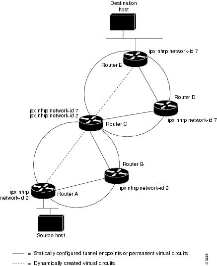
A logical NBMA network is considered the group of interfaces and hosts participating in NHRP and having the same network identifier. Figure 16 illustrates two logical NBMA networks (shown as circles) configured over a single physical NBMA network. Router A communicates with Routers B and C because they share the same network identifier (2). Router C also communicates with Routers D and E because they share network identifier 7. After address resolution is complete, Router A sends IPX packets to Router C in one hop, and Router C sends them to Router E in one hop, as shown by the dotted lines.
Figure 16 Two Logical NBMA Networks over One Physical NBMA Network
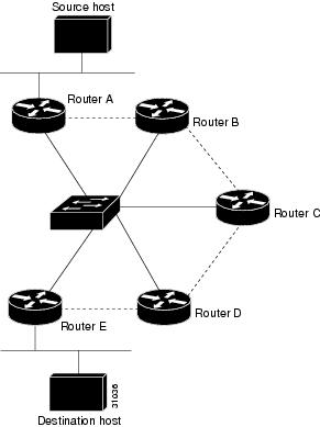
The physical configuration of the five routers in Figure 16 might actually be that shown in Figure 17. The source host is connected to Router A, and the destination host is connected to Router E. The same switch serves all five routers, making one physical NBMA network.
Figure 17 Physical Configuration of a Sample NBMA Network
Refer again to Figure 16. Initially, before NHRP resolves any NBMA addresses, IPX packets from the source host to the destination host travel through all five routers connected to the switch before reaching the destination. When Router A first forwards the IPX packet toward the destination host, Router A also generates an NHRP request for the destination host's IPX address. The request is forwarded to Router C, where a reply is generated. Router C replies because it is the egress router between the two logical NBMA networks.
Similarly, Router C generates an NHRP request of its own, to which Router E replies. In this example, subsequent IPX traffic between the source and the destination still requires two hops to traverse the NBMA network because the IPX traffic must be forwarded between the two logical NBMA networks. Only one hop would be required if the NBMA network was not logically divided.
NHRP over ATM Example
The following example shows how to configure three routers using NHRP over ATM. Router A is configured with a static route, which it uses to reach the IPX network where Router B resides. Router A initially reaches Router B through Router C. Router A and Router B directly communicate without Router C once NHRP resolves Router A's and Router C's respective NSAP addresses.
The significant portions of the configurations for Routers A, B, and C follow:
Configuration for Router A
interface ATM0/0map-group aatm nsap-address 11.1111.11.111111.1111.1111.1111.1111.1111.1111.11atm rate-queue 1 10atm pvc 1 0 5 qsaalipx network 1ipx nhrp network-id 1map-list aipx 1.0000.0c15.3588 atm-nsap 33.3333.33.333333.3333.3333.3333.3333.3333.3333.33ipx route 2 1.0000.0c15.3588Configuration for Router B
interface ATM0/0map-group aatm nsap-address 22.2222.22.222222.2222.2222.2222.2222.2222.2222.22atm rate-queue 1 10atm pvc 2 0 5 qsaalipx network 2ipx nhrp network-id 1map-list aipx 2.0000.0c15.3628 atm-nsap 33.3333.33.333333.3333.3333.3333.3333.3333.3333.33ipx route 1 2.0000.0c15.3628Configuration for Router C
interface ATM0/0atm rate-queue 1 10atm pvc 2 0 5 qsaalinterface ATM0/0.1 multipointmap-group aatm nsap-address 33.3333.33.333333.3333.3333.3333.3333.3333.3333.33ipx network 1ipx nhrp network-id 1interface ATM0/0.2 multipointmap-group batm nsap-address 33.3333.33.333333.3333.3333.3333.3333.3333.3333.33ipx network 2ipx nhrp network-id 2map-list aipx 1.0000.0c15.4f80 atm-nsap 11.1111.11.111111.1111.1111.1111.1111.1111.1111.11map-list bipx 2.0000.0c15.5021 atm-nsap 22.2222.22.222222.2222.2222.2222.2222.2222.2222.22IPX over WAN Examples
The following sections show examples of how to configure IPX over WAN and dial interfaces.
•
IPX over a WAN Interface Example
When you configure the Cisco IOS software to transport IPX packets over a serial interface that is running a WAN protocol such as X.25 or PPP, you specify how the packet will be encapsulated for transport. This encapsulation is not the same as the encapsulation used on an IPX LAN interface. Figure 18 illustrates IPX over a WAN interface.
Figure 18 IPX over a WAN Interface
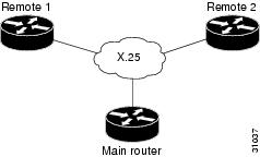
The following example shows how to configure a serial interface for X.25 encapsulation and for several IPX subinterfaces used in a nonmeshed topology:
Configuration for Main Router
hostname Main!no ip routingnovell routing 0000.0c17.d726!interface ethernet 0no ip addressNovell network 100media-type 10BaseT!interface serial 0no ip addressshutdown!interface serial 1no ip addressencapsulation x25x25 address 33333x25 htc 28!interface serial 1.1 point-to-pointno ip addressnovell network 2x25 map novell 2.0000.0c03.a4ad 11111 BROADCAST!interface serial 1.2 point-to-pointno ip addressnovell network 3x25 map novell 3.0000.0c07.5e26 55555 BROADCASTConfiguration for Router 1
hostname Remote1!no ip routingnovell routing 0000.0c03.a4ad!interface ethernet 0no ip addressnovell network 1!interface serial 0no ip addressencapsulation x25novell network 2x25 address 11111x25 htc 28x25 map novell 2.0000.0c17.d726 33333 BROADCASTConfiguration for Router 2
hostname Remote2!no ip routingnovell routing 0000.0c07.5e26!interface ethernet 0no ip addressnovell network 4media-type 10BaseT!interface serial 0no ip addressshutdown!interface serial 1no ip addressencapsulation x25novell network 3x25 address 55555x25 htc 28x25 map novell 3.0000.0c17.d726 33333 BROADCASTIPX over DDR Example
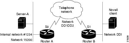
In the configuration shown in Figure 19, an IPX client is separated from its server by a DDR telephone line.
Figure 19 IPX over DDR Configuration
Routing and service information is sent every 60 seconds. The output RIP and SAP filters defined in this example filter these updates, preventing them from being sent between Router A and Router B. If you forwarded these packets, each of the two routers would need to telephone the other once every 60 seconds. On a serial link whose charges are based on the number of packets sent, this activity is generally not desirable. (This problem may not occur on a dedicated serial line.)
Once the server and client have established contact, the server will send watchdog keepalive packets regularly. When SPX is used, both the server and the client send keepalive packets whose purpose is to ensure that the connection between the server and the client is still functional; these packets contain no other information. Servers send watchdog packets approximately every 5 minutes.
If Router A were allowed to forward the keepalive packets of the server to Router B, Router A would need to telephone Router B every 5 minutes just to send these packets. Again, on a serial link whose charges are based on the number of packets sent, this activity is generally not desirable. Instead of having Router A telephone Router B only to send keepalive packets, you can enable watchdog spoofing on Router A. The result will be that when the server connected to this router sends keepalive packets, Router A will respond on behalf of the remote client (the client connected to Router B). When SPX is used, enable spoofing of SPX keepalive packets on both routers A and B to inhibit the sending of them because both the server and the client send keepalive packets.
Use the ipx watchdog-spoof interface configuration command to enable and set the duration of watchdog spoofing. You can specify the number of consecutive hours spoofing is to stay enabled and the number of minutes spoofing is to stay disabled. Use this command only on a serial interface whose fast switching and autonomous switching are disabled.
The following example shows how to configure Router A. Watchdog spoofing will be enabled for 1 hour and disabled for 20 minutes, allowing the server to clean up inactive connections before being enabled again.
ipx routing 0000.0c04.4878!interface Ethernet0ipx network 15200!interface Serial0 ! PPP encap for DDR(recommended)encapsulation pppipx network DD1DD2! Kill all rip updatesipx output-network-filter 801! Kill all sap updatesipx output-sap-filter 1001! fast-switching off for watchdog spoofingno ipx route-cache! Don't listen to ripipx router-filter 866! IPX watchdog spoofingipx watchdog-spoof 1 20!SPX watchdog spoofingipx spx-spoof! Turn on DDRdialer in-banddialer idle-timeout 200dialer map IP 198.92.96.132 name R13 7917dialer map IPX DD1DD2.0000.0c03.e3c3 7917dialer-group 1ppp authentication chap! Chap authentication requiredpulse-time 1!access-list 801 deny FFFFFFFFaccess-list 866 deny FFFFFFFF! Serialization packetsaccess-list 900 deny 0 FFFFFFFF 0 FFFFFFFF 457! RIP packetsaccess-list 900 deny 1 FFFFFFFF 453 FFFFFFFF 453! SAP packetsaccess-list 900 deny 4 FFFFFFFF 452 FFFFFFFF 452! Permit everything elseaccess-list 900 permit -1 FFFFFFFF 0 FFFFFFFF 0!access-list 1001 deny FFFFFFFF!! Static ipx route for remote networkipx route DD1 DD1DD2.0000.0c03.e3c3!!! IPX will trigger the line up (9.21 and later)dialer-list 1 list 900IPX Network Access Examples
The following sections show examples of how to control access to your IPX network. The sections show the configurations for various access lists and filters.
•
•
•
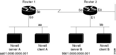
IPX Network Access Example
Using access lists to manage traffic routing is a powerful tool in overall network control. However, it requires a certain amount of planning and the appropriate application of several related commands. Figure 20 illustrates a network featuring two routers on two network segments.
Figure 20 Novell IPX Servers Requiring Access Control
Suppose you want to prevent clients and servers on Network aa from using the services on Network bb, but you want to allow the clients and servers on Network bb to use the services on Network aa. To achieve this configuration, you would need an access list on Ethernet interface 1 on Router 2 that blocks all packets coming from Network aa and destined for Network bb. You would not need any access list on Ethernet interface 0 on Router 1.
The following example shows how to configure Ethernet interface 1 on Router 2:
ipx routingaccess-list 800 deny aa bb01access-list 800 permit -1 -1interface ethernet 1ipx network bbipx access-group 800The following example shows how you can accomplish the same result as the previous example more efficiently by placing an input filter on interface Ethernet 0 of Router 1. You can also place the same output filter on Router 1, interface serial 0.
ipx routingaccess-list 800 deny aa bb01access-list 800 permit -1 -1interface ethernet 0ipx network aaipx access-group 800 in
Note
Logging Access Control List Violations
The following example shows how you can keep a log of all access control list violations by using the keyword log at the end of the access-list command:
access-list 907 deny -1 -1 0 100 0 logThe previous example denies and logs all packets that arrive at the router from any source in any protocol from any socket to any destination on network 100.
The following example shows a log entry for the access-list command:
%IPX-6-ACL: 907 deny SPX B5A8 50.0000.0000.0001 B5A8 100.0000.0000.0001 10 pktsIn this example, ten SPX packets were denied because they matched access list number 907. The packets were coming from socket B5A8 on networks 50.0000.0000.0001 and were destined for socket B5A8 on network 100.0000.0000.0001.
Standard Named Access List Example
The following example shows how to create a standard access list named fred. It denies communication with only IPX network number 5678.
ipx access-list standard freddeny 5678 anypermit anyExtended Named Access List Time Range Example
The following example shows how to create an extended access list named test. It permits SPX traffic only on Monday through Friday between the hours of 8:00 a.m. and 6:00 p.m.
time-range no-spxperiodic weekdays 8:00 to 18:00!ipx access-list extended testpermit spx any all any all time-range no spxSAP Input Filter Example
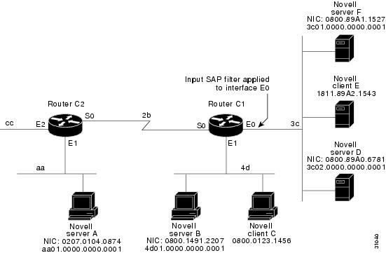
SAP input filters allow a router to determine whether to accept information about a service.
Router C1, illustrated in Figure 21, will not accept and, consequently not advertise, any information about Novell server F. However, Router C1 will accept information about all other servers on the network 3c. Router C2 receives information about servers D and B.Figure 21 SAP Input Filter
The following example shows how to configure Router C1. The first line denies server F, and the second line accepts all other servers.
access-list 1000 deny 3c01.0000.0000.0001access-list 1000 permit -1interface ethernet 0ipx network 3cipx input-sap-filter 1000interface ethernet 1ipx network 4dinterface serial 0ipx network 2b
Note
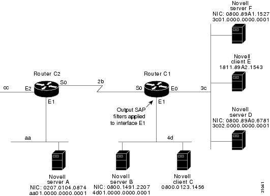
SAP Output Filter Example
SAP output filters are applied prior to the Cisco IOS software sending information out a specific interface. In the example that follows, Router C1 (illustrated in Figure 22) is prevented from advertising information about Novell server A out interface Ethernet 1, but can advertise server A on network 3c.
Figure 22 SAP Output Filter
The following example shows how to configure Router C1. The first line denies server A. All other servers are permitted.
access-list 1000 deny aa01.0000.0000.0001access-list 1000 permit -1interface ethernet 0novell net 3cinterface ethernet 1ipx network 4dipx output-sap-filter 1000interface serial 0ipx network 2bGGS SAP Response Filter Example
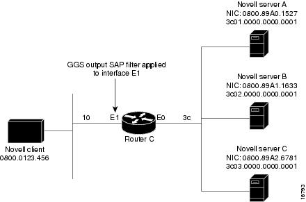
GGS SAP response filters as shown in Figure 23 allow a router to determine whether to forward information it receives about a service.
Figure 23 GGS SAP Response Filter
The following example shows how to configure GGS SAP response filters for Router C. When the client issues a GGS request, the output GGS filter denies a response from Novell Server A and permits responses from Novell servers B and C.
access-list 1000 deny 3c01.0000.0000.0001access-list 1000 permit -1interface ethernet 0ipx network 3cinterface ethernet 1ipx output-ggs-filter 1000ipx network 10IPX NetBIOS Filter Examples
The following example shows how to use a NetBIOS host name to filter IPX NetBIOS frames. The example denies all outgoing IPX NetBIOS frames with a NetBIOS host name of Boston on Ethernet interface 0.
netbios access-list host token deny Bostonnetbios access-list host token permit *!ipx routing 0000.0c17.d45d!interface ethernet 0ipx network 155 encapsulation ARPAipx output-rip-delay 60ipx triggered-rip-delay 30ipx output-sap-delay 60ipx triggered-sap-delay 30ipx type-20-propagationipx netbios output-access-filter host tokenno mop enabled!interface ethernet 1no ip addressipx network 105!interface fddi 0no ip addressno keepaliveipx network 305 encapsulation SAP!interface serial 0no ip addressshutdown!interface serial 1no ip addressno keepaliveipx network 600ipx output-rip-delay 100ipx triggered-rip-delay 60ipx output-sap-delay 100ipx triggered-sap-delay 60ipx type-20-propagationThe following example shows how to use a byte pattern to filter IPX NetBIOS frames. This example permits IPX NetBIOS frames from IPX network numbers that end in 05, which means that all IPX NetBIOS frames from Ethernet interface 1 (network 105) and FDDI interface 0 (network 305) will be forwarded by serial interface 0. However, this interface will filter out and not forward all frames from Ethernet interface 0 (network 155).
netbios access-list bytes finigan permit 2 **05!ipx routing 0000.0c17.d45d!ipx default-output-rip-delay 1000ipx default-triggered-rip-delay 100ipx default-output-sap-delay 1000ipx default-triggered-sap-delay 100!interface ethernet 0ipx network 155 encapsulation ARPAipx output-rip-delay 55ipx triggered-rip-delay 55ipx output-sap-delay 55ipx triggered-sap-delay 55ipx type-20-propagationmedia-type 10BaseT!interface ethernet 1no ip addressipx network 105ipx output-rip-delay 55ipx triggered-rip-delay 55ipx output-sap-delay 55ipx triggered-sap-delay 55media-type 10BaseT!interface fddi 0no ip addressno keepaliveipx network 305 encapsulation SAPipx output-sap-delay 55ipx triggered-sap-delay 55!interface serial 0no ip addressshutdown!interface serial 1no ip addressno keepaliveipx network 600ipx type-20-propagationipx netbios input-access-filter bytes finiganHelper Facilities to Control Broadcast Examples
The following sections show examples of how to control broadcast messages on IPX networks:
•
•
•
Note that in the following examples, packet Type 2 is used. This type has been chosen arbitrarily; the actual type to use depends on the specific application.
Forwarding to an Address Example
All broadcast packets are normally blocked by the Cisco IOS software. However, Type 20 propagation packets may be forwarded, subject to certain loop-prevention checks. Other broadcasts may be directed to a set of networks or a specific host (node) on a segment. The following examples illustrate these options.
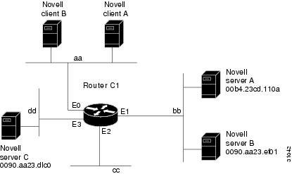
Figure 24 shows a router (C1) connected to several Ethernet interfaces. In this environment, all IPX clients are attached to segment aa, while all servers are attached to segments bb and dd. In controlling broadcasts, the following conditions are to be applied:
•
•
•
Figure 24 IPX Clients Requiring Server Access Through a Router
The following example shows how to configure the router shown in Figure 24. The first line permits broadcast traffic of Type 2 from network aa. The interface and network commands configure each specific interface. The ipx helper-address interface configuration commands permit broadcast forwarding from network aa to bb and from network aa to dd. The helper list allows Type 2 broadcasts to be forwarded. (Note that Type 2 broadcasts are chosen as an example only. The actual type to use depends on the specific application.) The ipx type-20-propagation interface configuration command is also required to allow Type 20 broadcasts. The IPX helper-list filter is applied to both the Type 2 packets forwarded by the helper-address mechanism and the Type 20 packets forwarded by Type 20 propagation.
access-list 900 permit 2 aainterface ethernet 0ipx network aaipx type-20-propagationipx helper-address bb.ffff.ffff.ffffipx helper-address dd.ffff.ffff.ffffipx helper-list 900interface ethernet 1ipx network bbinterface ethernet 3ipx network ddipx type-20-propagationThis configuration means that any network that is downstream from network aa (for example, some arbitrary network aa1) will not be able to broadcast (Type 2) to network bb through Router C1 unless the routers partitioning networks aa and aa1 are configured to forward these broadcasts with a series of configuration entries analogous to the example provided for Figure 24. These entries must be applied to the input interface and be set to forward broadcasts between directly connected networks. In this way, such traffic can be passed along in a directed manner from network to network. A similar situation exists for Type 20 packets.
The following example shows how to rewrite the ipx helper-address interface configuration command line to direct broadcasts to server A:
ipx helper-address bb.00b4.23cd.110a! Permits node-specific broadcast forwarding to! Server A at address 00b4.23cd.110a on network bb.Forwarding to All Networks Example
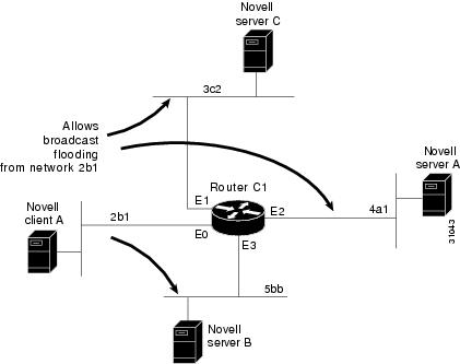
In some networks, it might be necessary to allow client nodes to broadcast to servers on multiple networks. If you configure your router to forward broadcasts to all attached networks, you are flooding the interfaces. In the environment illustrated in Figure 25, client nodes on network 2b1 must obtain services from IPX servers on networks 3c2, 4a1, and 5bb through Router C1. To support this requirement, use the flooding address (-1.ffff.ffff.ffff) in your ipx helper-address interface configuration command specifications.
Figure 25 Type 2 Broadcast Flooding
The first line in the following example shows how to permit traffic of Type 2 from network 2b1. Then the first interface is configured with a network number. The all-nets helper address is defined and the helper list limits forwarding to Type 2 traffic. Type 2 broadcasts from network 2b1 are forwarded to all directly connected networks. All other broadcasts, including Type 20, are blocked. To permit broadcasts, delete the ipx helper-list entry. To allow Type 20 broadcast, enable the ipx type-20-propagation interface configuration command on all interfaces.
access-list 901 permit 2 2b1interface ethernet 0ipx network 2b1ipx helper-address -1.ffff.ffff.ffffipx helper-list 901interface ethernet 1ipx network 3c2interface ethernet 2ipx network 4a1interface ethernet 3ipx network 5bbAll-Nets Flooded Broadcast Example
The following example shows how to configure all-nets flooding on an interface. As a result of this configuration, Ethernet interface 0 will forward all broadcast messages (except Type 20) to all the networks it knows how to reach. This flooding of broadcast messages might overwhelm these networks with so much broadcast traffic that no other traffic may be able to pass on them.
interface ethernet 0ipx network 23ipx helper-address -1.FFFF.FFFF.FFFFIPX Accounting Example
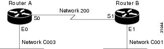
The following example shows how to configure two Ethernet network segments that are connected via a serial link (see Figure 26). On Router A, IPX accounting is enabled on both the input and output interfaces (that is, on Ethernet interface 0 and serial interface 0), which means that statistics are gathered for traffic traveling in both directions (that is, out to the Ethernet network and out the serial link).
On Router B, IPX accounting is enabled only on the serial interface and not on the Ethernet interface, which means that statistics are gathered only for traffic that passes out the router on the serial link. Also, the accounting threshold is set to 1000, which means that IPX accounting will track all IPX traffic passing through the router up to 1000 source and destination pairs.
Figure 26 IPX Accounting Example
Configuration for Router A
ipx routinginterface ethernet 0no ip addressipx network C003ipx accountinginterface serial 0no ip addressipx network 200ipx accountingConfiguration for Router B
ipx routinginterface ethernet 1no ip addressno keepaliveipx network C001no mop enabledinterface serial 1no ip addressipx network 200ipx accountingipx accounting-threshold 1000