Feedback Feedback
|
Table Of Contents
Lawful Intercept on Cisco 12000 Series Router ISE Line Cards
SNMPv3 Lawful Intercept Provisioning Interface
Implementation of Lawful Intercept
Lawful Intercept for Dial-up Calls
Related Features and Technologies
SNMP v3 Access for Lawful Intercept
Router Access Function Configuration
Call Agent Access Function Configuration
Surveillance Function Provisioning
Collection Function Provisioning
Lawful Intercept on Cisco 12000 Series Router ISE Line Cards
Part Number OL-8679-01 (Rev. A0) April 1, 2008
Feature History
See the following main sections for information about the Lawful Intercept feature:
Feature Overview
This feature module describes the Lawful Intercept functionality as it is implemented on the Cisco 12000 series routers.
The Feature Overview section contains the following sections:
•
Implementation of Lawful Intercept
•
•
Lawful Intercept Description
Lawful Intercept is the process by which law enforcement agencies conduct electronic surveillance of circuit and packet-mode communications as authorized by judicial or administrative order.
Service providers worldwide are already legally required to allow government agencies to conduct electronic surveillance on traditional telephone equipment. Lawful Intercept enables government agencies to conduct electronic surveillance on packet networks as well.
Note
Cisco Lawful Intercept is based on Service Independent Intercept (SII) architecture and Simple Network Management Protocol Version 3 (SNMP V3) provisioning architecture.
Cisco SII architecture supports Lawful Intercept with the following features:
•
•
•
•
The Cisco 12000 series routers support Lawful Intercept under SII architecture with the following features:
•
•
•
•
•
•
•
•
•
SNMPv3 Lawful Intercept Provisioning Interface
SNMPv3 is the provisioning interface for Cisco 12000 series router implementation of Lawful Intercept. SNMPv3 provides data origin authentication and secure connections. The law requires authentication and security so that unauthorized parties cannot observe or forge an intercept target.
Implementation of Lawful Intercept
There are two types of Cisco Lawful Intercepts on the Cisco 12000 series routers:
•
•
Lawful Intercept for VoIP
On Cisco 12000 series routers, Lawful Intercept for Voice over IP (VoIP) is done using SII architecture and SNMPv3 provisioning architecture. The mediation device provisions the intercept on the router using SNMPv3. The router intercepts the target Voice over IP (VoIP) calls and sends the intercepted data to the mediation device.
Before provisioning Lawful Intercept for Voice over IP (VoIP) can be done, the Lawful Intercept administrator must perform the following tasks.
1.
2.
3.
Lawful Intercept provisioning for Voice over IP (VoIP) on a Cisco 12000 series router is done as follows:
1.
2.
3.
4.
Voice over IP (VoIP) calls are intercepted as follows:
1.
2.
3.
4.
Content of intercepted Voice over IP (VoIP) is transmitted using UDP transport.
Lawful Intercept for Dial-up Calls
Cisco implements Lawful Intercept for dial-up calls using SII architecture and SNMP V3 provisioning architecture.
Before provisioning Lawful Intercept for dial-up calls can be done, the Lawful Intercept administrator must perform the following tasks.
•
•
•
On Cisco 12000 series routers, Lawful Intercept provisioning for dial-up calls is done as follows:
•
•
•
•
Dial-up calls are intercepted as follows:
1.
Note
2.
3.
4.
5.
Content of intercepted dial-up calls is transmitted using UDP transport.
Lawful Intercept Topology
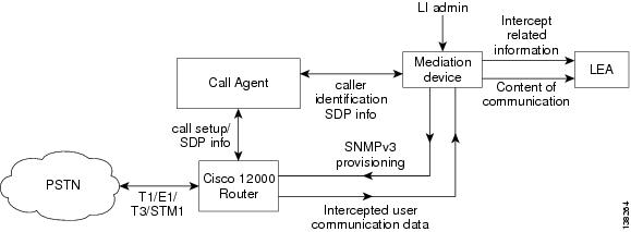
Figure 1 shows a Cisco 12000 series router in a Voice over IP (VoIP) network.
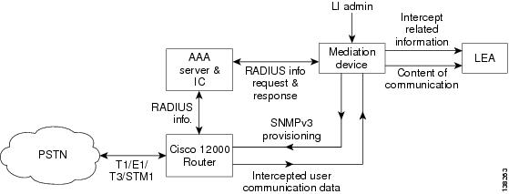
Figure 2 shows a Cisco 12000 series router in a dial-up access network.
Figure 1 Cisco 12000 series router in a VoIP Network
Figure 2 Cisco 12000 Series Router in a Dial-up Access Network
The following components are used in the network topology for a Voice over IP (VoIP) Lawful Intercept solution:
•
•
•
When an Media Gateway Control Protocol (MGCP) call agent must support the interface with the mediation device to provide the SDP signaling information. The router must support the mediation device extracts the intercept target's local IP/UDP address from the SDP signaling information to do the SNMPv3 Lawful Intercept provisioning. As long as the mediation device can use CISCO-TAP-MIB to provision an intercept, the router will be able to intercept the call.
Note
The following components are used in the network topology for a dial-up access Lawful Intercept solution:
•
•
•
•
For the dial-up Lawful Intercept solution, the sniffer device software caches the RADIUS server information. The mediation device obtains the Lawful Intercept provisioning information (such as the account session ID) from the sniffer. The mediation device provisions the intercept through the SNMPv3 interface using the CISCO-TAP-MIB.
Benefits
The Lawful Intercept feature provides service provides with the ability to meet law enforcement requirements and gives law enforcement agencies the ability to intercept Voice over IP (VoIP) and data traffic as it passes through edge routers.
Restrictions
When Lawful Intercept is enabled, forwarding performance of non-intercepted packets is degraded by 7 to 8 percent.
Network administrators are not able to observe Lawful Intercept is enabled. No Lawful Intercept program messages or error messages are ever displayed on the console.
Lawful Intercept on Cisco 12000 series routers does not provide the following features for Cisco IOS Release 12.0(32)S:
•
•
•
•
•
•
•
•
•
Related Features and Technologies
Lawful Intercept supports the following technologies on the Cisco 12000 series routers:
•
•
•
•
•
Related Documents
For general configuration information on the Cisco 12000 series routers, refer to the following documentation:
•
For information on how to configure a Cisco Media Gateway Controller (MGC), go to:
http://www.cisco.com/univercd/cc/td/doc/product/access/sc/rel9/swinstl/3ins_cfg.htm#wp1464984
Supported Platforms
Lawful Intercept for Cisco 12000 series routers is supported on Cisco IOS Release 12.0(32)S and is supported on all Cisco 12000 Series IP Services Engine (ISE) line cards.
Finding Support Information for Platforms and Cisco IOS Software Images
Use Cisco Feature Navigator to find information about platform support and Cisco IOS software image support. Access Cisco Feature Navigator at http://www.cisco.com/go/fn. You must have an account on Cisco.com. If you do not have an account or have forgotten your username or password, click Cancel at the login dialog box and follow the instructions.
Supported Standards and MIBs
Lawful Intercept on the Cisco 12000 series router conforms to the following standards and MIBs.
Standards
•
•
MIBs
•
VoIP Lawful Intercept Provisioning TAP-MIB
Voice over IP (VoIP) Lawful Intercept provisioning is based on the local media gateway IP address and the UDP port. The mediation device uses the CISCO-TAP-MIB to provision Voice over IP (VoIP) intercepts. In Voice over IP (VoIP) Lawful Intercept provisioning, an intercept can be enabled or disabled during a voice call.
Dial-up Lawful Intercept Provisioning TAP-MIB
Dial-up Lawful Intercept provisioning does not have fixed IP addresses. The IP addresses are assigned dynamically. The mediation device uses the CISCO-TAP-MIB to provision dial-up intercepts.
Prerequisites
Before you can provision Lawful Intercept on a Cisco 12000 series router, you must have the following components already set up:
•
•
Configuration Tasks
See the following sections for configuration tasks for the Lawful Intercept feature:
•
•
•
•
SNMP v3 Access for Lawful Intercept
SNMP v3 Access for Lawful Intercept is configured on the router. The configuration commands to setup the configuration for SNMP v3 access are as follows:
Note
router(config)#snmp-server group group3 v3 auth read view3 write view3 notify view3router(config)#snmp-server view view3 snmp-server view view3 cTapMIB includedrouter(config)#snmp-server view view3 ciscoUserConnectionTapMIB includedrouter(config)#snmp-server enable traps ttyThe following configuration command is not saved in NVRAM and must be entered every time the router boots up:
router(config)#snmp-server user SS8user group3 v3 auth md5 ciscoIn the above example, group3 is an SNMP v3 group, which can access the three MIBS specified in read/write mode. SS8user is a user that belongs to group3 and can provision the specified MIBS securely. You can change the names, SS8user and group3, to any value.
Mediation Device Provisioning
Cisco 12000 series router provisioning is done on the mediation device by the mediation device vendor. In this case, the SS8 mediation device is used as an example.
The mediation device
•
•
The SS8 mediation device vendor must provision the following three functions to complete Lawful Intercept provisioning on the SS8 mediation device for a Cisco 12000 series router:
•
•
•
Access Function Provisioning
The SS8 mediation device vendor must verify that the SS8 Access Function Table for Broadband Telephony Softswitch (BTS) is populated with the correct data as shown in the examples in Figure 3:
•
•
•
•
•
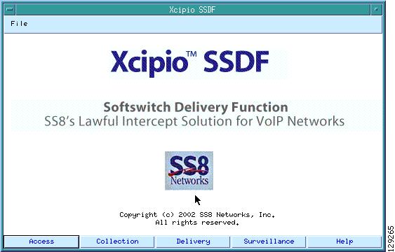
In the SS8 mediation device main window, select the Access button as shown in Figure 3.
Figure 3 SS8 Main Window with Access Selected
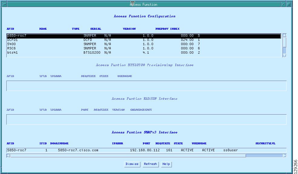
When you select the Access button, the Access Function Configuration table appears as shown in Figure 4.
Figure 4 Access Function Configuration Table
Router Access Function Configuration
In the Access Function Configuration table, manually set the following fields for each router in the surveillance path as shown in the example in Figure 4:
•
•
•
•
•
•
•
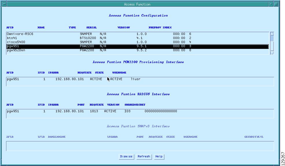
Call Agent Access Function Configuration
In the Access Function Configuration table, manually set the following fields for the call agent as show in the example in Figure 5:
•
•
•
•
•
•
•
Figure 5 Access Function Configuration Table—PGW Example
Surveillance Function Provisioning
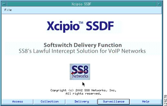
On the SS8 mediation device main window, select the Surveillance button as shown in Figure 6.
Figure 6 SS8 Main Window with Surveillance Selected
\
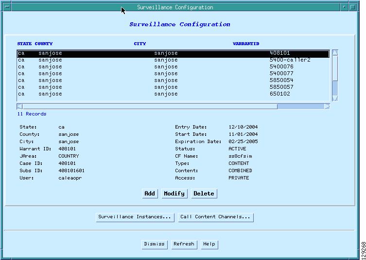
When you select the Surveillance button, the Surveillance Configuration Window appears as shown in Figure 7.
Figure 7 Surveillance Configuration Window
From the Surveillance Configuration window, perform the following steps:
Step 1
Step 2
•
•
Step 3
Step 4
Step 5
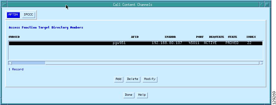
Step 6
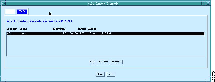
Figure 8 Call Content Channels—AFTDN Tab
Step 7
Figure 9 Call Content Channels—IPCCC Tab
Collection Function Provisioning
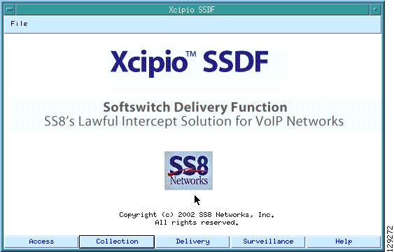
On the SS8 mediation device main window, select the Collection button as shown in Figure 10.
Figure 10 SS8 Main Window with Collection Selected
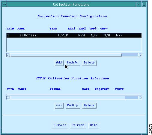
When you select the Collection button, the Collection Functions window appears as shown in Figure 11.
In the Collection Functions window, define the collection type.
Figure 11 show TCP/IP as the collection type.
Figure 11 Collection Functions Window
Call Agent Provisioning
In the CLI, register the call agent with the mediation device by entering the following code:
Note
mml>add-af:afid=pgw952Dan,type=PGW2200,version=9.5.2,preprov=000:00;mml>add-afgi:afid=pgw952Dan,ifid=1,ipaddr=192.168.80.129,username=liusr,passwd=test123;mml>add-fri:afid=pgw952Dan,ifid=1,ipaddr=192.168.80.129,port=1813,version=I03,sharedsecret =0000000000000000;Glossary
© 2006 Cisco Systems, Inc. All rights reserved.