Downloads |
 Feedback Feedback
|
Table Of Contents
Layer 2 Tunnel Protocol Version 3
Prerequisites for Layer 2 Tunnel Protocol Version 3
Restrictions for Layer 2 Tunnel Protocol Version 3
Supported Port Adapters for the Cisco 7200 and 7500 Series Routers
Cisco 7200-Specific Restrictions
Cisco 7500-Specific Restrictions
Cisco 10720-Specific Restrictions
Cisco 12000 Series-Specific Restrictions
Frame Relay-Specific Restrictions
ATM VP Mode Single Cell Relay over L2TPv3 Restrictions
ATM AAL5 SDU over L2TPv3 and Single Cell Relay VC Mode over L2TPv3 Restrictions
ATM Port Mode Cell Relay over L2TPv3 Restrictions
ATM Cell Packing over L2TPv3 Restrictions
Protocol Demultiplexing for L2TPv3 Restrictions
L2TPv3 Control Message Hashing Restrictions
Information About Layer 2 Tunnel Protocol Version 3
Pseudowire Control Encapsulation
L2TPv3 Type of Service Marking
L2TPv3 Control Connection Hashing
L2TPv3 Control Connection Rate Limiting
L2TPv3 and UTI Feature Comparison
How to Configure Layer 2 Tunnel Protocol Version 3
Configuring L2TP Control Channel Parameters
Configuring L2TP Control Channel Timing Parameters
Configuring L2TPv3 Control Channel Authentication Parameters
Configuring L2TP Control Channel Maintenance Parameters
Configuring the L2TPv3 Pseudowire
Configuring the Xconnect Attachment Circuit
Manually Configuring L2TPv3 Session Parameters
Configuring the Xconnect Attachment Circuit for ATM VP Mode Single Cell Relay over L2TPv3
Configuring the Xconnect Attachment Circuit for ATM Single Cell Relay VC Mode over L2TPv3
Configuring the Xconnect Attachment Circuit for ATM Port Mode Cell Relay over L2TPv3
Configuring the Xconnect Attachment Circuit for ATM Cell Packing over L2TPv3
Configuring Port Mode ATM Cell Packing over L2TPv3
Configuring VP Mode ATM Cell Packing over L2TPv3
Configuring VC Mode ATM Cell Packing over L2TPv3
Configuring the Xconnect Attachment Circuit for ATM AAL5 SDU Mode over L2TPv3
Configuring OAM Local Emulation for ATM AAL5 over L2TPv3
Configuring Protocol Demultiplexing for L2TPv3
Configuring Protocol Demultiplexing for Ethernet Interfaces
Configuring Protocol Demultiplexing for Frame Relay Interfaces
Configuration Examples for Layer 2 Tunnel Protocol Version 3
Configuring Frame Relay DLCI-to-DLCI Switching Example
Configuring Frame Relay Trunking Example
Configuring QoS for L2TPv3 on the Cisco 7500 Series Example
Configuring QoS for L2TPv3 on the Cisco 12000 Series Example
Configuring MLFR for L2TPv3 on the Cisco 12000 Series Example
Configuring an MQC for Committed Information Rate Guarantees Example
Configuring a Static L2TPv3 Session for an Xconnect Ethernet Interface Example
Configuring a Negotiated L2TPv3 Session for an Xconnect VLAN Subinterface Example
Configuring a Negotiated L2TPv3 Session for Local HDLC Switching Example
Configuring a Pseudowire Class for Fragmentation of IP Packets Example
Setting the Frame Relay DE Bit Configuration Example
Matching the Frame Relay DE Bit Configuration Example
Configuring the Xconnect Attachment Circuit for ATM VP Mode Single Cell Relay over L2TPv3 Example
Configuring ATM Single Cell Relay VC Mode over L2TPv3 Example
Configuring ATM Port Mode Cell Relay over L2TPv3 Example
Configuring ATM Cell Packing over L2TPv3 Examples
Configuring the Xconnect Attachment Circuit for ATM AAL5 SDU Mode over L2TPv3 Example
Configuring OAM Local Emulation for ATM AAL5 over L2TPv3 Example
Configuring Protocol Demultiplexing for L2TPv3 Examples
Configuring L2TPv3 Control Connection Authentication Examples
Verifying an L2TPv3 Session Example
Verifying an L2TP Control Channel Example
Verifying ATM VP Mode Single Cell Relay over L2TPv3 Configuration Example
Verifying ATM AAL5 SDU Mode over L2TPv3 Configuration Example
Verifying OAM Local Emulation for ATM AAL5 over L2TPv3 Example
Verifying ATM VCC Cell Relay over L2TPv3 Example
snmp-server enable traps l2tun session
Layer 2 Tunnel Protocol Version 3
The Layer 2 Tunnel Protocol Version 3 feature expands on Cisco support of the Layer 2 Tunnel Protocol Version 3 (L2TPv3). L2TPv3 is an Internet Engineering Task Force (IETF) l2tpext working group draft that provides several enhancements to L2TP for the capability to tunnel any Layer 2 payload over L2TP. Specifically, L2TPv3 defines the L2TP protocol for tunneling Layer 2 payloads over an IP core network using Layer 2 virtual private networks (VPNs). Benefits of this feature include the following:
•
L2TPv3 simplifies deployment of VPNs
•
•
Feature History for the Layer 2 Tunneling Protocol Version 3
Feature
Finding Support Information for Platforms and Cisco IOS Software Images
Use Cisco Feature Navigator to find information about platform support and Cisco IOS software image support. Access Cisco Feature Navigator at http://www.cisco.com/go/fn. You must have an account on Cisco.com. If you do not have an account or have forgotten your username or password, click Cancel at the login dialog box and follow the instructions that appear.
Contents
•
•
•
•
•
Prerequisites for Layer 2 Tunnel Protocol Version 3
•
•
•
Restrictions for Layer 2 Tunnel Protocol Version 3
The following subsections contain information on restrictions:
•
•
•
•
•
•
•
•
•
•
•
•
Supported Port Adapters for the Cisco 7200 and 7500 Series Routers
L2TPv3 is supported on the following port adapters in the Cisco 7200 and 7500 series routers:
•
•
•
•
•
•
•
•
•
•
•
•
•
•
•
•
•
•
•
•
•
•
•
•
•
•
•
•
•
•
•
L2TPv3 is supported on the following port adapters for the Cisco 7200 series routers only:
•
•
General L2TPv3 Restrictions
•
•
•
When L2TPv3 is used to tunnel Frame Relay D channel data-link connection identifiers (DLCIs), an IDB is not required for each circuit. As a result, the memory requirements are much lower. The scalability targets for the Engineering Field Test (EFT) program are 4000 L2TP session.
•
•
•
•
•
•
Cisco 7200-Specific Restrictions
•
•
Cisco 7500-Specific Restrictions
•
•
•
Cisco 10720-Specific Restrictions
•
•
•
•
You can also configure a LAN interface as the IP local interface so that the tunnel control session is tied to an operational LAN (Gigabit Ethernet or Fast Ethernet) interface or subinterface. However, in this case, the tunnel control plane is used only as long as the Gigabit Ethernet or Fast Ethernet interface is operational.
Cisco 12000 Series-Specific Restrictions
•
•
•
•
•
•
•
•
•
•
•
•
•
•
•
–
–
•
•
Frame Relay-Specific Restrictions
•
•
•
•
•
–
–
The police command is supported as follows:
•
•
•
Backward explicit congestion notification (BECN) and forward explicit congestion notification (FECN) configuration are not supported.
The Type of Service (ToS) byte must be configured in IP headers of tunneled Frame Relay packets when you configure the L2TPv3 pseudowire (see Configuring the L2TPv3 Pseudowire).
All standard restrictions for configuring QoS on Cisco 12000 series line cards apply to configuring QoS for L2TPv3 on Cisco 12000 series 2-port Ch OC-3/STM-1 (DS1/E1) or 6-port Ch T3 line cards.
On the ingress side of a Cisco 12000 series Frame Relay interface:
•
On the egress side of a Cisco 12000 series Frame Relay interface:
•
•
•
With both a low latency (priority) queue and class-default queue configured. (The low latency queue is only supported in combination with the class-default queue, and cannot be configured with normal distributed round robin (DRR) queues.)
Without a low latency queue configured. (In this case, only 6 queues are supported, including the class-default queue.)
•
•
•
•
•
•
•
VLAN-Specific Restrictions
•
•
•
ATM VP Mode Single Cell Relay over L2TPv3 Restrictions
•
•
ATM AAL5 SDU over L2TPv3 and Single Cell Relay VC Mode over L2TPv3 Restrictions
•
•
•
•
•
ATM Port Mode Cell Relay over L2TPv3 Restrictions
•
•
•
ATM Cell Packing over L2TPv3 Restrictions
•
•
Protocol Demultiplexing for L2TPv3 Restrictions
•
•
•
•
•
•
•
•
L2TPv3 Control Message Hashing Restrictions
•
•
Information About Layer 2 Tunnel Protocol Version 3
To configure the Layer 2 Tunnel Protocol Version 3 feature, you must understand the following concepts:
•
Migration from UTI to L2TPv3
UTI is a Cisco proprietary protocol that offers a simple high-speed transparent Layer 2-to-Layer 2 service over an IP backbone. The UTI protocol lacks the signaling capability and standards support necessary for large-scale commercial service. To begin to answer the need for a standard way to provide large-scale VPN connectivity over an IP core network, limited migration from UTI to L2TPv3 was introduced in Cisco IOS Release 12.0(21)S. The L2TPv3 feature in Cisco IOS Release 12.0(23)S introduced a more robust version of L2TPv3 to replace UTI.
As described in the section "L2TPv3 Header Description," the UTI data header is identical to the L2TPv3 header but with no sequence numbers and an 8-byte cookie. By manually configuring an L2TPv3 session using an 8-byte cookie (see the section "Manually Configuring L2TPv3 Session Parameters") and by setting the IP protocol number of outgoing data packets to 120 (as described in the section "Configuring the L2TPv3 Pseudowire"), you can ensure that a PE running L2TPv3 may interoperate with a peer PE running UTI. However, because UTI does not define a signaling plane, dynamically established L2TPv3 sessions cannot interoperate with UTI.
When a customer upgrades from a pre-L2TPv3 Cisco IOS release to a post-L2TPv3 release, an internal UTI-to-Xconnect command-line interface (CLI) migration utility will automatically convert the UTI commands to Xconnect and pseudowire class configuration commands without the need for any user intervention. After the CLI migration, the UTI commands that were replaced will not be available. The old-style UTI CLI will be hidden from the user.
Note
L2TPv3 Operation
L2TPv3 provides similar and enhanced services to replace the current UTI implementation, including the following features:
•
•
The initial Cisco IOS Release 12.0(23)S features supported only the following features:
•
•
•
•
The attachment circuit is the physical interface or subinterface attached to the pseudowire.
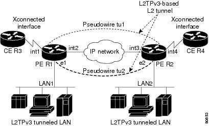
Figure 1 shows an example of how the L2TPv3 feature is used for setting up VPNs using Layer 2 tunneling over an IP network. All traffic between two customer network sites is encapsulated in IP packets carrying L2TP data messages and sent across an IP network. The backbone routers of the IP network treat the traffic as any other IP traffic and need not know anything about the customer networks.
Figure 1 L2TPv3 Operation
In Figure 1, the PE routers R1 and R2 provide L2TPv3 services. The R1 and R2 routers communicate with each other using a pseudowire over the IP backbone network through a path comprising the interfaces int1 and int2, the IP network, and interfaces int3 and int4.
In this example, the CE routers R3 and R4 communicate through a pair of Xconnect Ethernet or 802.1q VLAN interfaces using an L2TPv3 session. The L2TPv3 session tu1 is a pseudowire configured between interface int1 on R1 and interface int4 on R2. Any packet arriving on interface int1 on R1 is encapsulated and sent via the pseudowire control channel (tu1) to R2. R2 decapsulates the packet and sends it on interface int4 to R4. When R4 needs to send a packet to R3, the packet follows the same path in reverse.
Please note the following features regarding L2TPv3 operation:
•
•
•
Benefits of Using L2TPv3
L2TPv3 Simplifies Deployment of VPNs
L2TPv3 is an industry-standard Layer 2 tunneling protocol that ensures interoperability among vendors, increasing customer flexibility and service availability.
L2TPv3 Does Not Require MPLS
With L2TPv3 service providers need not deploy MPLS in the core IP backbone to set up VPNs using L2TPv3 over the IP backbone, resulting in operational savings and increased revenue.
L2TPv3 Supports Layer 2 Tunneling over IP for Any Payload
L2TPv3 provides enhancements to L2TP to support Layer 2 tunneling of any payload over an IP core network. L2TPv3 defines the base L2TP protocol as being separate from the Layer 2 payload that is tunneled.
L2TPv3 Header Description
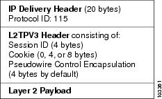
The migration from UTI to L2TPv3 also requires the standardization of the UTI header. As a result, the L2TPv3 header has the new format shown in Figure 2.
Figure 2
L2TPv3 Header Format
Each L2TPv3 packet contains an L2TPv3 header that includes a unique session ID representing one session and a variable cookie length. The L2TPv3 session ID and the Tunnel Cookie field length are assigned via the CLI. See the section "How to Configure Layer 2 Tunnel Protocol Version 3" for more information on the CLI commands for L2TPv3.
Session ID
The L2TPv3 session ID is similar to the UTI session ID, and identifies the session context on the decapsulating system. For dynamic sessions, the value of the session ID is selected to optimize the context identification efficiency of the decapsulating system. A decapsulation implementation may therefore elect to support a smaller session ID bit field. In this L2TPv3 implementation, an upper value for the L2TPv3 session ID was set at 023. The L2TPv3 session ID value 0 is reserved for use by the protocol. For static sessions, the session ID is manually configured.
Note
Session Cookie
The L2TPv3 header contains a control channel cookie field that is similar to the UTI control channel key field. The control channel cookie field, however, has a variable length of 0, 4, or 8 bytes according to the cookie length supported by a given platform for packet decapsulation. The control channel cookie length can be manually configured for static sessions, or dynamically determined for dynamic sessions.
The variable cookie length does not present a problem when the same platform is at both ends of an L2TPv3 control channel. However, when different platforms interoperate across an L2TPv3 control channel, both platforms need to encapsulate packets with a 4-byte cookie length.
Pseudowire Control Encapsulation
The L2TPv3 pseudowire control encapsulation consists of 32 bits (4 bytes) and contains information used to sequence L2TP packets (see the section "Sequencing") and to distinguish AAL5 data and OAM cells for AAL5 SDU mode over L2TPv3. For the purposes of sequencing, only the first bit and bits 8 to 31 are relevant.
Bit 1 indicates whether the Sequence Number field, bits 8 to 31, contains a valid sequence number and is to be updated.
L2TPv3 Features
L2TPv3 provides Xconnect support for Ethernet, 802.1q (VLAN), Frame Relay, HDLC, and PPP, using the sessions described in the following sections:
•
•
L2TPv3 also includes support for the features described in the following sections:
•
•
•
Static L2TPv3 Sessions
Typically, the L2TP control plane is responsible for negotiating session parameters, such as the session ID or the cookie, in order to set up the session. However, some IP networks require sessions to be configured so that no signaling is required for session establishment. You can, therefore, set up static L2TPv3 sessions for a PE router by configuring fixed values for the fields in the L2TP data header. A static L2TPv3 session allows the PE to tunnel Layer 2 traffic as soon as the attachment circuit to which the session is bound comes up.
Note
When you use a static L2TPv3 session, you cannot perform circuit interworking, such as LMI, because there is no facility to exchange control messages. To perform circuit interworking, you must use a dynamic session.
Dynamic L2TPv3 Sessions
A dynamic L2TP session is established through the exchange of control messages containing attribute-value pairs (AVPs). Each AVP contains information about the nature of the Layer 2 link being forwarded: the payload type, virtual circuit (VC) ID, and so on.
Multiple L2TP sessions (one for each forwarded Layer 2 circuit) can exist between a pair of PEs, and can be maintained by a single control channel. Session IDs and cookies are dynamically generated and exchanged as part of a dynamic session setup. Information such as sequencing configuration is also exchanged. Circuit state changes (UP/DOWN) are conveyed using the set link info (SLI) message.
Sequencing
Although the correct sequence of received Layer 2 frames is guaranteed by some Layer 2 technologies (by the nature of the link, such as a serial line) or the protocol itself, forwarded Layer 2 frames may be lost, duplicated, or reordered when they traverse a network as IP packets. If the Layer 2 protocol does not provide an explicit sequencing mechanism, you can configure L2TP to sequence its data packets according to the data channel sequencing mechanism described in the L2TPv3 IETF l2tpext working group draft.
A receiver of L2TP data packets mandates sequencing through the Sequencing Required AVP when the session is being negotiated. A sender that receives this AVP (or that is manually configured to send sequenced packets) uses the Layer 2-specific pseudowire control encapsulation defined in L2TPv3.
Currently, you can configure L2TP only to drop out-of-order packets; you cannot configure L2TP to deliver the packets out-of-order. No reordering mechanism is available.
Cisco IOS Software Release 12.0(28)S introduces support for L2TPv3 distributed sequencing on the Cisco 7500 series routers.
Local Switching
Local switching (from one port to another port in the same router) is supported for both static and dynamic sessions. You must configure separate IP addresses for each Xconnect statement.
See the section "Configuration Examples for Layer 2 Tunnel Protocol Version 3" for an example of how to configure local port switching.
Distributed Switching
Distributed CEF switching is supported for L2TP on the Cisco 7500 series routers.
Note
IP Packet Fragmentation
It is desirable to avoid fragmentation issues in the service provider network because reassembly is computationally expensive. The easiest way to avoid fragmentation issues is to configure the CE routers with an path maximum transmission unit (MTU) value that is smaller than the pseudowire path MTU. However, in scenarios where this is not an option, fragmentation issues must be considered. L2TP initially supported only the following options for packet fragmentation when a packet is determined to exceed the L2TP path MTU:
•
•
•
Cisco IOS Release 12.0(24)S introduced the ability to allow IP traffic from the CE router to be fragmented before the data enters the pseudowire, forcing the computationally expensive reassembly to occur in the CE network rather than in the service provider network. The number of fragments that must be generated is determined based on the discovered pseudowire path MTU. The original Layer 2 header is then copied to each of the generated fragments, the L2TP/IP encapsulation is added, and the frames are then forwarded. This feature will be implicitly enabled whenever the ip pmtu command is enabled in the pseudowire class. It will be applied to any packets received from the CE network that have a Don't Fragment (DF) bit set to 0 and that exceed the L2TP path MTU in size.
Support for the fragmentation of IP packets before the data enters the pseudowire was introduced on the Cisco 7200 series and Cisco 7500 series routers in Cisco IOS Release 12.0(24)S.
L2TPv3 Type of Service Marking
When Layer 2 traffic is tunneled across an IP network, information contained in the ToS bits may be transferred to the L2TP-encapsulated IP packets in one of the following ways:
•
•
See the section "Configuring a Negotiated L2TPv3 Session for Local HDLC Switching Example" for more information about how to configure ToS information.
Keepalive
The keepalive mechanism for L2TPv3 extends only to the endpoints of the tunneling protocol. L2TP has a reliable control message delivery mechanism that serves as the basis for the keepalive mechanism. The keepalive mechanism consists of an exchange of L2TP hello messages.
If a keepalive mechanism is required, the control plane is used, although it may not be used to bring up sessions. You can manually configure sessions.
In the case of static L2TPv3 sessions, a control channel between the two L2TP peers is negotiated through the exchange of start control channel request (SCCRQ), start control channel replay (SCCRP), and start control channel connected (SCCCN) control messages. The control channel is responsible only for maintaining the keepalive mechanism through the exchange of hello messages.
The interval between hello messages is configurable per control channel. If one peer detects that the other has gone down through the keepalive mechanism, it sends a StopCCN control message and then notifies all of the pseudowires to the peer about the event. This notification results in the teardown of both manually configured and dynamic sessions.
MTU Handling
It is important that you configure an MTU appropriate for a each L2TPv3 tunneled link. The configured MTU size ensures the following:
•
•
L2TPv3 handles the MTU as follows:
•
•
•
–
–
L2TPv3 Control Connection Hashing
The L2TPv3 Control Connection Hashing feature introduces a new and more secure authentication system that replaces the Challenge Handshake Authentication Protocol (CHAP)-like authentication system inherited from L2TPv2, which uses the Challenge and Challenge Response AVPs in the SCCRQ, SCCRP, and SCCCN messages.
The per-message authentication introduced by the L2TPv3 Control Connection Hashing feature is designed to perform a mutual authentication between L2TP nodes, check integrity of all control messages, and guard against control message spoofing and replay attacks that would otherwise be trivial to mount against the network.
L2TPv3 Control Connection Hashing incorporates an optional authentication or integrity check for all control messages. The new authentication method uses a computed one-way hash over the header and body of the L2TP control message, a pre-configured shared secret that must be defined on communicating L2TP nodes, and a local and remote random value exchanged via the Nonce AVPs. Received control messages that lack any of the required security elements are dropped.
L2TPv3 control connection integrity checking is a unidirectional mechanism that does not require the configuration of a shared secret. If integrity checking is enabled on the local PE router, control messages are sent with the message digest calculated without the shared secret or Nonce AVPs, and are verified by the remote PE router. If verification fails, the remote PE router drops the control message.
L2TPv3 Control Connection Rate Limiting
Cisco IOS Release 12.0(29)S introduces the L2TPv3 Control Connection Rate Limiting feature to counter the possibility of a denial-of-service attack on a router running L2TPv3. The L2TPv3 Control Connection Rate Limiting feature limits the rate at which SCCRQ control packets arriving at the PE that terminates the L2TPv3 tunnel can be processed. SCCRQ control packets initiate the process of bringing up the L2TPv3 tunnel and require a large amount of the control plane resources of the PE router.
On distributed platforms, most control packet filtering will occur at the line card level, and the CPU of the RP will be minimally impacted even in a worst-case denial-of-service attack scenario. This feature will have minimal impact on the shared bus or switching fabric, which are typically the bottleneck of a router.
No configuration is required for the L2TPv3 Control Connection Rate Limiting feature. This feature will automatically run in the background of Cisco IOS Release 12.0(29)S and subsequent releases.
L2TPv3 and UTI Feature Comparison
Table 1 compares L2TPv3 and UTI support for the Cisco 7200 and Cisco 7500 series routers.
Supported L2TPv3 Payloads
L2TPv3 supports the following Layer 2 payloads that can be included in L2TPv3 packets tunneled over the pseudowire:
•
•
•
Note
Frame Relay
L2TPv3 supports the Frame Relay functionality described in the following sections:
•
Port-to-Port Trunking
Port-to-port trunking is where two CE Frame Relay interfaces are connected as by a leased line (UTI "raw" mode). All traffic arriving on one interface is forwarded transparently across the pseudowire to the other interface.
For example, in Figure 1, if the two CE routers are connected by a virtual leased line, the PE routers transparently transport all packets between CE R3 and CE R4 over a pseudowire. PE R1 and PE R2 do not examine or change the DLCIs, and do not participate in the LMI protocol. The two CE routers are LMI peers. There is nothing Frame Relay-specific about this service as far as the PE routers are concerned. The CE routers should be able to use any encapsulation based on HDLC framing without needing to change the provider configuration.
DLCI-to-DLCI Switching
Frame Relay DLCI-to-DLCI switching is where individual Frame Relay DLCIs are connected to create an end-to-end Frame Relay PVC. Traffic arriving on a DLCI on one interface is forwarded across the pseudowire to another DLCI on the other interface.
For example, in Figure 1, CE R3 and PE R1 are Frame Relay LMI peers; CE R4 and PE R2 are also LMI peers. You can use a different type of LMI between CE R3 and PE R1 compared to what you use between CE R4 and PE R2.
The CE devices may be a Frame Relay switch or end-user device. Each Frame Relay PVC is composed of multiple segments. The DLCI value is local to each segment and is changed as traffic is switched from segment to segment. Note that, in Figure 1, two Frame Relay PVC segments are connected by a pseudowire. Frame Relay header flags (FECN, BECN, C/R, DE) are preserved across the pseudowire.
PVC Status Signaling
PVC status signaling is propagated toward Frame Relay end users by the LMI protocol. You can configure the LMI to operate in any of the following modes:
•
•
•
L2TPv3 supports all three modes.
The PVC status should be reported as ACTIVE only if the PVC is available from the reporting device to the Frame Relay end-user device. All interfaces, line protocols, and pseudowires must be operational between the reporting device and the Frame Relay end-user device.
Note that any keepalive functions on the session are independent of Frame Relay, but any state changes that are detected are fed into the PVC status reporting. For example, the L2TP control channel uses hello packets as a keepalive function. If the L2TPv3 keepalive fails, all L2TPv3 sessions are torn down. Loss of the session is notified to Frame Relay, which can then report PVCs INACTIVE to the CE devices.
For example, in Figure 1, CE R3 reports ACTIVE to PE R1 only if the PVC is available within CE R3. When CE R3 is a switch, it reports all the way to the user device in the customer network.
PE R1 reports ACTIVE to CE R3 only if the PVC is available within PE R1 and all the way to the end-user device (via PE R2 and CE R3) in the other customer VPN site.
The ACTIVE state is propagated hop-by-hop, independently in each direction, from one end of the Frame Relay network to the other end.
Sequencing
Frame Relay provides an ordered service in which packets sent to the Frame Relay network by one end-user device are delivered in order to the other end-user device. When switching is occurring over the pseudowire, packet ordering must be able to be preserved with a very high probability to closely emulate a traditional Frame Relay service. If the CE router is not using a protocol that can detect misordering itself, configuring sequence number processing may be important. For example, if the Layer 3 protocol is IP and Frame Relay is therefore used only for encapsulation, sequencing is not required. To detect misordering, you can configure sequence number processing separately for transmission or reception. For more information about how to configure sequencing, see the section "Configuring a Negotiated L2TPv3 Session for Local HDLC Switching Example."
ToS Marking
The ToS bytes in the IP header can be statically configured or reflected from the internal IP header. The Frame Relay discard eligible (DE) bit does not influence the ToS bytes.
CIR Guarantees
In order to provide committed information rate (CIR) guarantees, you can configure a queueing policy that provides bandwidth to each DLCI to the interface facing the customer network on the egress PE.
Note
Binding L2TPv3 Sessions to Multilink Frame Relay Interfaces
The configuration of an L2TPv3 session on a Multilink Frame Relay (MLFR) bundle interface is supported only on Cisco 12000 series Two-Port Channelized OC-3/STM-1 (DS1/E1) and Six-Port Channelized T3 (T1) line cards.
The Multilink Frame Relay feature introduces functionality based on the Frame Relay Forum Multilink Frame Relay UNI/NNI Implementation Agreement (FRF.16). This feature provides a cost-effective way to increase bandwidth for particular applications by enabling multiple serial links to be aggregated into a single bundle of bandwidth.
For an example of how to configure L2TPv3 tunneling on a multilink Frame Relay bundle interface, see Configuring MLFR for L2TPv3 on the Cisco 12000 Series Example.
For information about how configure and use the MLFR feature, refer to the Multilink Frame Relay (FRF.16) publication.
Ethernet
An Ethernet frame arriving at a PE router is simply encapsulated in its entirety with an L2TP data header. At the other end, a received L2TP data packet is stripped of its L2TP data header. The payload, an Ethernet frame, is then forwarded to the appropriate attachment circuit.
Because the L2TPv3 tunneling protocol serves essentially as a bridge, it need not examine any part of an Ethernet frame. Any Ethernet frame received on an interface is tunneled, and any L2TP-tunneled Ethernet frame is forwarded out the interface.
Note
802.1q (VLAN)
L2TPv3 supports VLAN membership in the following ways:
•
•
In L2TPv3, Ethernet Xconnect supports port-based VLAN membership and the reception of tagged Ethernet frames. A tagged Ethernet frame contains a tag header (defined in 802.1Q), which is 4 bytes long and consists of a 2-byte tag protocol identifier (TPID) field and a 2-byte tag control information (TCI) field. The TPID indicates that a TCI follows. The TCI is further broken down into the following three fields:
•
•
•
For L2TPv3, an Ethernet subinterface configured to support VLAN switching may be bound to an Xconnect service so that all Ethernet traffic, tagged with a VID specified on the subinterface, is tunneled to another PE. The VLAN Ethernet frames are forwarded in their entirety. The receiving PE may rewrite the VID of the tunneled traffic to another value before forwarding the traffic onto an attachment circuit.
To successfully rewrite VLANs, it may be necessary to disable the Spanning Tree Protocol (STP). This can be done on a per-VLAN basis by using the no spanning-tree vlan command.
Note
HDLC
L2TPv3 encapsulates an HDLC frame arriving at a PE in its entirety (including the Address, Control, and Protocol fields, but not the Flag fields and the frame check sequence) with an L2TP data header.
PPP
PEs that support L2TPv3 forward PPP traffic using a "transparent pass-through" model, in which the PEs play no role in the negotiation and maintenance of the PPP link. L2TPv3 encapsulates a PPP frame arriving at a PE in its entirety (including the HDLC Address and Control fields) with an L2TP data header.
ATM
L2TPv3 can connect two isolated ATM clouds over a packet-switched network (PSN) while maintaining an end-to-end ATM Service Level Agreement (SLA). The ATM Single Cell Relay features forward one ATM cell per packet. The ATM Cell Packing over L2TPv3 features allows multiple ATM frames to be packed into a single L2TPv3 data packet. All packets are transparently forwarded over the L2TPv3 pseudowire.
Note
Table 2 shows the releases that introduced support for the ATM cell relay features.
ATM VP Mode Single Cell Relay over L2TPv3
The ATM VP Mode Single Cell Relay over L2TPv3 feature allows cells coming into a predefined PVP on the ATM interface to be transported over an L2TPv3 pseudowire to a predefined PVP on the egress ATM interface. A single ATM cell is encapsulated into each L2TPv3 data packet.
ATM Single Cell Relay VC Mode over L2TPv3
The ATM Single Cell Relay VC mode over L2TPv3 feature maps one VC to a single L2TPv3 session. All ATM cells arriving at an ATM interface with the specified VPI and VCI are encapsulated into a single L2TP packet. Each ATM cell will have a 4-byte ATM cell header without Header Error Control Checksum (HEC) and a 48-byte ATM cell payload.
The ATM Single Cell Relay VC mode feature can be used to carry any type of AAL traffic over the pseudowire. It will not distinguish OAM cells from User data cells. In this mode, Performance and Security OAM cells are also transported over the pseudowire.
ATM Port Mode Cell Relay over L2TPv3
The ATM Port Mode Cell Relay over L2TPv3 feature packs ATM cells arriving at an ingress ATM interface into L2TPv3 data packets and transports them to the egress ATM interface. A single ATM cell is encapsulated into each L2TPv3 data packet.
ATM Cell Packing over L2TPv3
The ATM Cell Packing over L2TPv3 feature enhances throughput and uses bandwidth more efficiently than the ATM cell relay features. Instead of a single ATM cell being packed into each L2TPv3 data packet, multiple ATM cells can be packed into a single L2TPv3 data packet. ATM cell packing is supported for Port mode, VP mode, and VC mode. Cell packing must be configured on the PE devices. No configuration is required on the CE devices.
ATM AAL5 over L2TPv3
The ATM AAL5 over L2TPv3 feature maps the AAL5 payload of an AAL5 PVC to a single L2TPv3 session. This service will transport OAM and RM cells, but does not attempt to maintain the relative order of these cells with respect to the cells that comprise the AAL5 common part convergence sublayer protocol data unit (CPCS-PDU). OAM cells that arrive during the reassembly of a single AAL5 CPCS-PDU are sent immediately over the pseudowire, followed by the AAL5 payload without the AAL5 pad and trailer bytes.
OAM Transparent Mode
In OAM transparent mode, the PEs will pass the following OAM cells transparently across the pseudowire:
•
•
Note
OAM Local Emulation Mode
In OAM Local Emulation mode, OAM cells are not passed through the pseudowire. All F5 OAM cells are terminated and handled locally. On the L2TPv3-based pseudowire, the CE device sends an SLI message across the pseudowire to notify the peer PE node about the defect, rather than tearing down the session. The defect can occur at any point in the link between the local CE and the PE. OAM management can also be enabled on the PE node using existing OAM management configurations.
IPv6 Protocol Demultiplexing
Upgrading a service provider network to support IPv6 is a long and expensive process. As an interim solution, the Protocol Demultiplexing for L2TPv3 feature introduces the ability to provide native IPv6 support by setting up a specialized IPv6 network and offloading IPv6 traffic from the IPv4 network. IPv6 traffic is transparently tunneled to the IPv6 network using L2TPv3 pseudowires without affecting the configuration of the CE routers. IPv4 traffic is routed as usual within the IPv4 network, maintaining the existing performance and reliability of the IPv4 network.
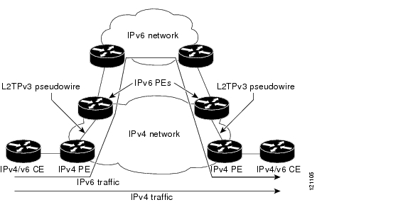
Figure 3 shows a network deployment that offloads IPv6 traffic from the IPv4 network to a specialized IPv6 network. The PE routers demultiplex the IPv6 traffic from the IPv4 traffic. IPv6 traffic is routed to the IPv6 network over an L2TPv3 pseudowire, while IPv4 traffic is routed normally. The IPv4 PE routers must be configured to demultiplex incoming IPv6 traffic from IPv4 traffic. The PE routers facing the IPv6 network do not require demultiplexing configuration.
Figure 3
Protocol Demultiplexing of IPv6 Traffic from IPv4 Traffic
IPv6 protocol demultiplexing is supported only for Ethernet and Frame Relay traffic in Cisco IOS Release 12.0(29)S. Protocol demultiplexing requires supporting the combination of an IP address and an xconnect command configuration on the IPv4 PE interface. This combination of configurations is not allowed without enabling protocol demultiplexing, with the exception of switched Frame Relay PVCs. If no IP address is configured, the protocol demultiplexing configuration is rejected. If an IP address is configured, the xconnect command configuration is rejected unless protocol demultiplexing is enabled in xconnect configuration mode before exiting that mode. If an IP address is configured with an xconnect command configuration and protocol demultiplexing enabled, the IP address cannot be removed. To change or remove the configured IP address, the xconnect command configuration must first be disabled.
Table 3 shows the valid combinations of configurations.
Table 3 Valid Configuration Scenarios
Routing
Yes
No
—
L2VPN
No
Yes
No
IPv6 Protocol Demultiplexing
Yes
Yes
Yes
How to Configure Layer 2 Tunnel Protocol Version 3
This section contains the following procedures:
•
•
•
•
•
•
•
•
•
•
•
Configuring L2TP Control Channel Parameters
The L2TP class configuration procedure creates a template of L2TP control channel parameters that can be inherited by different pseudowire classes. L2TP control channel parameters are used in control channel authentication, keepalive messages, and control channel negotiation. In an L2TPv3 session, the same L2TP class must be specified in the pseudowire configured on the PE router at each end of the control channel. Configuring L2TP control channel parameters is optional. However, the L2TP class must be configured before it is with associated a pseudowire class (see the section "Configuring the L2TPv3 Pseudowire").
The three main groups of L2TP control channel parameters that you can configure in an L2TP class are described in the following sections:
•
•
•
After you enter L2TP class configuration mode, you can configure L2TP control channel parameters in any order. If you have multiple authentication requirements you can configure multiple sets of L2TP class control channel parameters with different L2TP class names. However, only one set of L2TP class control channel parameters can be applied to a connection between any pair of IP addresses.
Configuring L2TP Control Channel Timing Parameters
The following L2TP control channel timing parameters can be configured in L2TP class configuration mode:
•
•
•
This task configures a set of timing control channel parameters in an L2TP class. All of the timing control channel parameter configurations are optional and may be configured in any order. If these parameters are not configured, the default values are applied.
SUMMARY STEPS
1.
2.
3.
4.
5.
6.
DETAILED STEPS
Configuring L2TPv3 Control Channel Authentication Parameters
Two methods of control channel authentication are available in Cisco IOS Release 12.0(29)S. The L2TPv3 Control Channel Hashing feature introduces a more robust authentication method than the older CHAP-style L2TP control channel method of authentication. You may choose to enable both methods of authentication to ensure interoperability with peers that support only one of these methods of authentication, but this configuration will yield control of which authentication method is used to the peer PE router. Enabling both methods of authentication should be considered an interim solution to solve backward-compatibility issues during software upgrades.
The principal difference between the L2TPv3 Control Connection Authentication feature and CHAP-style L2TP control channel authentication is that, instead of computing the hash over selected contents of a received control message, the L2TPv3 Control Connection Authentication feature uses the entire message in the hash. In addition, instead of including the hash digest in only the SCCRP and SCCCN messages, it includes it in all L2TP messages.
Support for the L2TPv3 Control Connection Authentication feature is introduced in Cisco IOS Release 12.0(29)S. Support for L2TP control channel authentication is maintained for backward compatibility. Either or both authentication methods can be enabled to allow interoperability with peers supporting only one of the authentication methods.
Table 4 shows a compatibility matrix for the different L2TPv3 authentication methods. PE1 is running Cisco IOS 12.0(29)S, and the different possible authentication configurations for PE1 are shown in the first column. Each remaining column represents PE2 running software with different available authentication options, and the intersections indicate the different compatible configuration options for PE2. If any PE1/PE2 authentication configuration poses ambiguity on which method of authentication will be used, the winning authentication method is indicated in bold. If both the old and new authentication methods are enabled on PE1 and PE2, both types of authentication will occur.
Table 4 Compatibility Matrix for L2TPv3 Authentication Methods
None
None
None
New integrity check
None
New integrity check
Old authentication
Old authentication
—
Old authentication
Old authentication and new authentication
Old authentication and new integrity check
New authentication
—
New authentication
New authentication
Old authentication and new authentication
New integrity check
None
None
New integrity check
None
New integrity check
Old and new authentication
Old authentication
New authentication
Old authentication
New authentication
Old and new authentication
Old authentication and new integrity check
Old authentication and new integrity check
Old authentication
—
Old authentication
Old authentication and new authentication
Old authentication and new integrity check
1 Any PE software that supports only the old CHAP-like authentication system.
2 Any PE software that supports only the new message digest authentication and integrity checking authentication system, but does not understand the old CHAP-like authentication system. This type of software may be implemented by other vendors based on the latest L2TPv3 draft.
3 Any PE software that supports both the old CHAP-like authentication and the new message digest authentication and integrity checking authentication system, such as Cisco IOS 12.0(29)S or later releases.
Perform one or both of the following tasks to configure authentication parameters for the L2TPv3 control channel:
•
•
Configuring Authentication for the L2TP Control Channel
The L2TP control channel method of authentication is the older, CHAP-like authentication system inherited from L2TPv2.
The following L2TP control channel authentication parameters can be configured in L2TP class configuration mode:
•
•
•
This task configures a set of authentication control channel parameters in an L2TP class. All of the authentication control channel parameter configurations are optional and may be configured in any order. If these parameters are not configured, the default values will be applied.
SUMMARY STEPS
1.
2.
3.
4.
5.
6.
DETAILED STEPS
Configuring L2TPv3 Control Channel Hashing
The L2TPv3 Control Channel Hashing feature introduced in Cisco IOS Release 12.0(29)S is a new authentication system that is more secure than the CHAP-style L2TP control channel method of authentication. L2TPv3 Control Connection Hashing incorporates an optional authentication or integrity check for all control messages. This per-message authentication is designed to guard against control message spoofing and replay attacks that would otherwise be trivial to mount against the network.
Enabling the L2TPv3Control Channel Hashing feature will impact performance during control connection and session establishment because additional digest calculation of the full message content is required for each sent and received control message. This is an expected trade-off for the additional security afforded by this feature. In addition, network congestion may occur if the receive window size is too small. If the L2TPv3 Control Channel Hashing feature is enabled, message digest validation must be enabled. Message digest validation deactivates the data path received sequence number update and restricts the minimum local receive window size to 35.
You may choose to configure control message authentication or control message integrity checking. The control message authentication requires participation by both peers, and a shared secret must be configured on both routers. The control message integrity check is unidirectional, and requires configuration on only one of the peers.
This task configures L2TPv3 Control Channel Hashing feature for an L2TP class.
SUMMARY STEPS
1.
2.
3.
4.
5.
6.
DETAILED STEPS
Step 1
enable
Example:Router> enable
Enables privileged EXEC mode.
•
Step 2
configure terminal
Example:Router# configure terminal
Enters global configuration mode.
Step 3
l2tp-class [l2tp-class-name]
Example:Router(config)# l2tp-class class1
Specifies the L2TP class name and enters L2TP class configuration mode.
•
Step 4
digest [secret [0 | 7] password] [hash {md5 | sha}]
Example:Router(config-l2tp-class)# digest secret cisco hash sha
or
Router(config-l2tp-class)# digest hash sha
(Optional) Enables L2TPv3 control connection authentication or integrity checking.
•
Note
•
–
–
•
•
–
–
The default hash function is md5.
Step 5
digest check
Example:Router(config-l2tp-class)# digest check
(Optional) Enables the validation of the message digest in received control messages.
•
Note
Step 6
hidden
Example:Router(config-l2tp-class)# hidden
(Optional) Enables AVP hiding when sending control messages to an L2TPv3 peer.
•
•
•
Note
Configuring L2TP Control Channel Maintenance Parameters
The L2TP hello packet keepalive interval control channel maintenance parameter can be configured in L2TP class configuration mode.
This task configures the interval used for hello messages in an L2TP class. This control channel parameter configuration is optional. If this parameter is not configured, the default value will be applied.
SUMMARY STEPS
1.
2.
3.
4.
DETAILED STEPS
Configuring the L2TPv3 Pseudowire
The pseudowire class configuration procedure creates a configuration template for the pseudowire. You use this template, or class, to configure session-level parameters for L2TPv3 sessions that will be used to transport attachment circuit traffic over the pseudowire.
The pseudowire configuration specifies the characteristics of the L2TPv3 signaling mechanism, including the data encapsulation type, the control protocol, sequencing, fragmentation, payload-specific options, and IP properties. The setting that determines if signaling is used to set up the pseudowire is also included.
For simple L2TPv3 signaling configurations on most platforms, pseudowire class configuration is optional. However, specifying a source IP address to configure a loopback interface is highly recommended. If you do not configure a loopback interface, the router will choose the best available local address, which could be any IP address configured on a core-facing interface. This configuration could prevent a control channel from being established. On the Cisco 12000 series Internet routers, specifying a source IP address is mandatory, and you should configure a loopback interface that is dedicated for the use of L2TPv3 sessions exclusively. If you do not configure other pseudowire class configuration commands, the default values are used.
Once you specify the encapsulation l2tpv3 command, you cannot remove it using the no encapsulation l2tpv3 command. Nor can you change the command's setting using the encapsulation mpls command. Those methods result in the following error message:
Encapsulation changes are not allowed on an existing pw-class.To remove the command, you must delete the pseudowire with the no pseudowire-class command. To change the type of encapsulation, remove the pseudowire with the no pseudowire-class command and re-establish the pseudowire and specify the new encapsulation type.
SUMMARY STEPS
1.
2.
3.
4.
5.
6.
7.
8.
9.
10.
11.
12.
DETAILED STEPS
Step 1
enable
Example:Router> enable
Enables privileged EXEC mode.
•
Step 2
configure terminal
Example:Router# configure terminal
Enters global configuration mode.
Step 3
pseudowire-class [pw-class-name]
Example:Router(config)# pseudowire-class etherpw
Enters pseudowire class configuration mode and optionally specifies the name of the L2TP pseudowire class.
Step 4
encapsulation l2tpv3
Example:Router(config-pw)# encapsulation l2tpv3
Specifies that L2TPv3 is used as the data encapsulation method to tunnel IP traffic.
Step 5
protocol {l2tpv3 | none}[l2tp-class-name]
Example:Router(config-pw)# protocol l2tpv3 class1
(Optional) Specifies the L2TPv3 signaling protocol to be used to manage the pseudowires created with the control channel parameters in the specified L2TP class (see the section "Configuring L2TP Control Channel Parameters").
•
•
Step 6
ip local interface interface-name
Example:Router(config-pw)# ip local interface e0/0
Specifies the PE router interface whose IP address is to be used as the source IP address for sending tunneled packets.
•
Note
Step 7
ip pmtu
Example:Router(config-pw)# ip pmtu
(Optional) Enables the discovery of the path MTU for tunneled traffic.
•
Note
•
Note
Step 8
ip tos {value value | reflect}
Example:Router(config-pw)# ip tos reflect
(Optional) Configures the value of the ToS byte in IP headers of tunneled packets, or reflects the ToS byte value from the inner IP header.
•
Step 9
ip dfbit set
Example:Router(config-pw)# ip dfbit set
(Optional) Configures the value of the DF bit in the outer headers of tunneled packets.
•
Step 10
ip ttl value
Example:Router(config-pw)# ip ttl 100
(Optional) Configures the value of the time to live (TTL) byte in the IP headers of tunneled packets.
•
Step 11
ip protocol {l2tp | uti | protocol-number}
Example:Router(config-pw)# ip protocol uti
(Optional) Configures the IP protocol to be used for tunneling packets.
•
Step 12
sequencing {transmit | receive | both}
Example:Router(config-pw)# sequencing both
(Optional) Specifies the direction in which sequencing of data packets in a pseudowire is enabled:
•
•
•
Configuring the Xconnect Attachment Circuit
This configuration procedure binds an Ethernet, 802.1q VLAN, or Frame Relay attachment circuit to an L2TPv3 pseudowire for Xconnect service. The virtual circuit identifier that you configure creates the binding between a pseudowire configured on a PE router and an attachment circuit in a CE device. The virtual circuit identifier configured on the PE router at one end of the L2TPv3 control channel must also be configured on the peer PE router at the other end.
SUMMARY STEPS
1.
2.
3.
4.
DETAILED STEPS
Step 1
enable
Example:Router> enable
Enables privileged EXEC mode.
•
Step 2
configure terminal
Example:Router# configure terminal
Enters global configuration mode.
Step 3
interface type slot/port
Example:Router(config)# interface ethernet 0/0
Specifies the interface by type (for example, Ethernet) and slot and port number, and enters interface configuration mode.
Step 4
xconnect peer-ip-address vcid pseudowire-parameters [sequencing {transmit | receive | both}]
Example:Router(config-if)# xconnect 10.0.3.201 123 pw-class vlan-xconnect
Specifies the IP address of the peer PE router and the 32-bit virtual circuit identifier shared between the PE at each end of the control channel.
•
•
–
•
•
•
–
•
•
Note
Note
•
Manually Configuring L2TPv3 Session Parameters
When you bind an attachment circuit to an L2TPv3 pseudowire for Xconnect service using the xconnect l2tpv3 manual command (see the section "Configuring the Xconnect Attachment Circuit") because you do not want signaling, you must then configure L2TP-specific parameters to complete the L2TPv3 control channel configuration.
SUMMARY STEPS
1.
2.
3.
4.
5.
6.
7.
8.
DETAILED STEPS
Step 1
enable
Example:Router> enable
Enables privileged EXEC mode.
•
Step 2
configure terminal
Example:Router# configure terminal
Enters global configuration mode.
Step 3
interface type slot/port
Example:Router(config)# interface ethernet 0/0
Specifies the interface by type (for example, Ethernet) and slot and port number, and enters interface configuration mode.
Step 4
xconnect peer-ip-address vc-id encapsulation l2tpv3 manual pw-class pw-class-name
Example:Router(config-if)# xconnect 10.0.3.201 123 encapsulation l2tpv3 manual pw-class vlan-xconnect
Specifies the IP address of the peer PE router and the 32-bit virtual circuit identifier shared between the PE at each end of the control channel.
•
•
•
Step 5
l2tp id local-session-id remote-session-id
Example:Router(config-if-xconn)# l2tp id 222 111
Configures the identifiers for the local L2TPv3 session and for the remote L2TPv3 session on the peer PE router.
•
Step 6
l2tp cookie local size low-value [high-value]
Example:Router(config-if-xconn)# l2tp cookie local 4 54321
(Optional) Specifies the value that the peer PE must include in the cookie field of incoming (received) L2TP packets.
•
•
Step 7
l2tp cookie remote size low-value [high-value]
Example:Router(config-if-xconn)# l2tp cookie remote 4 12345
(Optional) Specifies the value that the router includes in the cookie field of outgoing (sent) L2TP packets.
•
•
Step 8
l2tp hello l2tp-class-name
Example:Router(config-if-xconn)# l2tp hello l2tp-defaults
(Optional) Specifies the L2TP class name to use (see the section "Configuring L2TP Control Channel Parameters") for control channel configuration parameters, including the interval to use between hello keepalive messages.
Note
Configuring the Xconnect Attachment Circuit for ATM VP Mode Single Cell Relay over L2TPv3
The ATM VP Mode Single Cell Relay over L2TPv3 feature allows cells coming into a predefined PVP on the ATM interface to be transported over an L2TPv3 pseudowire to a predefined PVP on the egress ATM interface. This task binds a PVP to an L2TPv3 pseudowire for Xconnect service.
SUMMARY STEPS
1.
2.
3.
4.
5.
DETAILED STEPS
Configuring the Xconnect Attachment Circuit for ATM Single Cell Relay VC Mode over L2TPv3
The ATM Single Cell Relay VC Mode over L2TPv3 feature maps one VCC to a single L2TPv3 session. All ATM cells arriving at an ATM interface with the specified VPI and VCI are encapsulated into a single L2TP packet.
The ATM Single Cell Relay VC mode feature can be used to carry any type of AAL traffic over the pseudowire. It will not distinguish OAM cells from User data cells. In this mode, PM and Security OAM cells are also transported over the pseudowire.
Perform this task to enable the ATM Single Cell Relay VC Mode over L2TPv3 feature.
SUMMARY STEPS
1.
2.
3.
4.
5.
6.
DETAILED STEPS
Step 1
enable
Example:Router> enable
Enables privileged EXEC mode.
•
Step 2
configure terminal
Example:Router# configure terminal
Enters global configuration mode.
Step 3
interface type slot/port
Example:Router(config)# interface ATM 4/1
Specifies the interface by type, slot, and port number, and enters interface configuration mode.
Step 4
pvc [name] vpi/vci l2transport
Example:Router(config-if)# pvc 5/500 l2transport
Creates or assigns a name to an ATM PVC, specifies the encapsulation type on an ATM PVC, and enters ATM VC configuration mode.
•
Step 5
encapsulation aal0
Example:Router(config-atm-vc)# encapsulation aal0
Specifies ATM AAL0 encapsulation for the PVC.
Step 6
xconnect peer-ip-address vcid pw-class pw-class-name
Example:Router(config-atm-vc)# xconnect 10.0.3.201 888 pw-class atm-xconnect
Specifies the IP address of the peer PE router and the 32-bit VCI shared between the PE at each end of the control channel.
•
•
Note
Configuring the Xconnect Attachment Circuit for ATM Port Mode Cell Relay over L2TPv3
The ATM Port Mode Cell Relay feature packs ATM cells arriving at an ingress ATM interface into L2TPv3 data packets and transports them to the egress ATM interface. A single ATM cell is encapsulated into each L2TPv3 data packet.
Perform this task to enable the ATM Port Mode Cell Relay over L2TPv3 feature.
SUMMARY STEPS
1.
2.
3.
4.
DETAILED STEPS
Step 1
enable
Example:Router> enable
Enables privileged EXEC mode.
•
Step 2
configure terminal
Example:Router# configure terminal
Enters global configuration mode.
Step 3
interface type slot/port
Example:Router(config)# interface ATM 4/1
Specifies the interface by type, slot, and port number, and enters interface configuration mode.
Step 4
xconnect peer-ip-address vcid pw-class pw-class-name
Example:Router(config-if)# xconnect 10.0.3.201 888 pw-class atm-xconnect
Specifies the IP address of the peer PE router and the 32-bit VCI shared between the PE at each end of the control channel.
•
•
Note
Configuring the Xconnect Attachment Circuit for ATM Cell Packing over L2TPv3
The ATM Cell Packing over L2TPv3 feature allows multiple ATM frames to be packed into a single L2TPv3 data packet. ATM cell packing can be configured for Port mode, VP mode, and VC mode. Perform one of the following tasks to configure the ATM Cell Packing over L2TPv3 feature:
•
•
•
Configuring Port Mode ATM Cell Packing over L2TPv3
Perform this task to configure port mode ATM cell packing over L2TPv3.
SUMMARY STEPS
1.
2.
3.
4.
5.
6.
DETAILED STEPS
Configuring VP Mode ATM Cell Packing over L2TPv3
Perform this task to configure VP mode ATM cell packing over L2TPv3.
SUMMARY STEPS
1.
2.
3.
4.
5.
6.
7.
DETAILED STEPS
Configuring VC Mode ATM Cell Packing over L2TPv3
Perform this task to configure VC mode ATM cell packing over L2TPv3.
SUMMARY STEPS
1.
2.
3.
4.
5.
6.
7.
8.
DETAILED STEPS
Configuring the Xconnect Attachment Circuit for ATM AAL5 SDU Mode over L2TPv3
The ATM AAL5 SDU Mode feature maps the AAL5 payload of an AAL5 PVC to a single L2TPv3 session. This service will transport OAM and RM cells, but does not attempt to maintain the relative order of these cells with respect to the cells that comprise the AAL5 CPCS-PDU. OAM cells that arrive during the reassembly of a single AAL5 CPCS-PDU are sent immediately over the pseudowire, followed by the AAL5 SDU payload.
This task binds a PVC to an L2TPv3 pseudowire for Xconnect service.
SUMMARY STEPS
1.
2.
3.
4.
5.
6.
DETAILED STEPS
Step 1
enable
Example:Router> enable
Enables privileged EXEC mode.
•
Step 2
configure terminal
Example:Router# configure terminal
Enters global configuration mode.
Step 3
interface type slot/port
Example:Router(config)# interface ATM 4/1
Specifies the interface by type, slot, and port number, and enters interface configuration mode.
Step 4
pvc [name] vpi/vci [l2transport]
Example:Router(config-if)# pvc 5/500 l2transport
Creates or assigns a name to an ATM permanent virtual circuit (PVC), specifies the encapsulation type on an ATM PVC, and enters ATM VC configuration mode.
•
Step 5
encapsulation aal5
Example:Router(config-atm-vc)# encapsulation aal5
Specifies ATM AAL5 encapsulation for the PVC.
Step 6
xconnect peer-ip-address vcid pw-class pw-class-name
Example:Router(config-atm-vc)# xconnect 10.0.3.201 888 pw-class atm-xconnect
Specifies the IP address of the peer PE router and the 32-bit VCI shared between the PE at each end of the control channel.
•
•
Note
Configuring OAM Local Emulation for ATM AAL5 over L2TPv3
If a PE router does not support the transport of OAM cells across an L2TPv3 session, you can use OAM cell emulation to locally terminate or loopback the OAM cells. You configure OAM cell emulation on both PE routers. You use the oam-ac emulation-enable command on both PE routers to enable OAM cell emulation.
After you enable OAM cell emulation on a router, you can configure and manage the ATM VC in the same manner as you would a terminated VC. A VC that has been configured with OAM cell emulation can send loopback cells at configured intervals toward the local CE router. The endpoint can be either of the following:
•
•
The OAM cells have the following information cells:
•
•
These cells identify and report defects along a VC. When a physical link or interface failure occurs, intermediate nodes insert OAM AIS cells into all the downstream devices affected by the failure. When a router receives an AIS cell, it marks the ATM VC as down and sends an RDI cell to let the remote end know about the failure.
Perform this task to enable OAM local emulation for AAL5 over L2TPv3.
SUMMARY STEPS
1.
2.
3.
4.
5.
6.
7.
DETAILED STEPS
Step 1
enable
Example:Router> enable
Enables privileged EXEC mode.
•
Step 2
configure terminal
Example:Router# configure terminal
Enters global configuration mode.
Step 3
interface type slot/port
Example:Router(config)# interface ATM 4/1
Specifies the interface by type, slot, and port number, and enters interface configuration mode.
Step 4
pvc [name] vpi/vci [l2transport]
Example:Router(config-if)# pvc 5/500 l2transport
Creates or assigns a name to an ATM PVC, specifies the encapsulation type on an ATM PVC, and enters ATM VC configuration mode.
•
Step 5
encapsulation aal5
Example:Router(config-atm-vc)# encapsulation aal5
Specifies ATM AAL5 encapsulation for the PVC.
Step 6
xconnect peer-ip-address vcid pw-class pw-class-name
Example:Router(config-atm-vc)# xconnect 10.0.3.201 888 pw-class atm-xconnect
Specifies the IP address of the peer PE router and the 32-bit VCI shared between the PE at each end of the control channel.
•
•
Note
Step 7
oam-ac emulation-enable [ais-rate]
Example:Router(config-atm-vc)# oam-ac emulation-enable 30
Enables OAM cell emulation on AAL5 over L2TPv3.
•
Configuring Protocol Demultiplexing for L2TPv3
The Protocol Demultiplexing feature introduces the ability to provide native IPv6 support by utilizing a specialized IPv6 network to offload IPv6 traffic from the IPv4 network. IPv6 traffic is transparently tunneled to the IPv6 network using L2TPv3 pseudowires without affecting the configuration of the CE routers. IPv4 traffic is routed as usual within the IPv4 network, maintaining the existing performance and reliability of the IPv4 network.
The IPv4 PE routers must be configured to demultiplex incoming IPv6 traffic from IPv4 traffic. The PE routers facing the IPv6 network do not require demultiplexing configuration. The configuration of the IPv6 network is beyond the scope of this document. For more information on configuring an IPv6 network, refer to the Cisco IOS IPv6 Configuration Library.
Perform one of the following tasks on the customer-facing IPv4 PE routers to enable IPv6 protocol demultiplexing:
•
•
Configuring Protocol Demultiplexing for Ethernet Interfaces
Perform this task to configure the Protocol Demultiplexing feature on an Ethernet interface.
SUMMARY STEPS
1.
2.
3.
4.
5.
6.
DETAILED STEPS
Step 1
enable
Example:Router> enable
Enables privileged EXEC mode.
•
Step 2
configure terminal
Example:Router# configure terminal
Enters global configuration mode.
Step 3
interface type slot/port
Example:Router(config)# interface ethernet 0/1
Specifies the interface by type, slot, and port number, and enters interface configuration mode.
Step 4
ip address ip-address mask [secondary]
Example:Router(config-if)# ip address 172.16.128.4
Sets a primary or secondary IP address for an interface.
Step 5
xconnect peer-ip-address vcid pw-class pw-class-name
Example:Router(config-if)# xconnect 10.0.3.201 888 pw-class demux
Specifies the IP address of the peer PE router and the 32-bit VCI shared between the PE at each end of the control channel and enters Xconnect configuration mode.
•
•
Note
Step 6
match protocol ipv6
Example:Router(config-if-xconn)# match protocol ipv6
Enables protocol demultiplexing of IPv6 traffic.
Configuring Protocol Demultiplexing for Frame Relay Interfaces
Perform this task to configure the Protocol Demultiplexing feature on a Frame Relay interface.
SUMMARY STEPS
1.
2.
3.
4.
5.
6.
7.
DETAILED STEPS
Step 1
enable
Example:Router> enable
Enables privileged EXEC mode.
•
Step 2
configure terminal
Example:Router# configure terminal
Enters global configuration mode.
Step 3
interface type slot/port-adapter.subinterface- number [multipoint | point-to-point]
Example:Router(config)# interface serial 1/1.2 multipoint
Specifies the interface by type, slot, and port number, and enters interface configuration mode.
Step 4
ip address ip-address mask [secondary]
Example:Router(config-if)# ip address 172.16.128.4
Sets a primary or secondary IP address for an interface.
Step 5
frame-relay interface-dlci dlci [ietf | cisco] [voice-cir cir] [ppp virtual-template-name]
Example:Router(config-if)# frame-relay interface-dlci 100
Assigns a DLCI to a specified Frame Relay subinterface on the router or access server, assigns a specific PVC to a DLCI, or applies a virtual template configuration for a PPP session and enters Frame Relay DLCI interface configuration mode.
Step 6
xconnect peer-ip-address vcid pw-class pw-class-name
Example:Router(config-fr-dlci)# xconnect 10.0.3.201 888 pw-class atm-xconnect
Specifies the IP address of the peer PE router and the 32-bit VCI shared between the PE at each end of the control channel and enters Xconnect configuration mode.
•
•
Note
Step 7
match protocol ipv6
Example:Router(config-if-xconn)# match protocol ipv6
Enables protocol demultiplexing of IPv6 traffic.
Configuration Examples for Layer 2 Tunnel Protocol Version 3
This section provides the following configuration examples:
•
•
•
•
•
•
•
•
•
•
•
•
•
•
•
•
•
•
•
•
•
•
•
•
•
•
Configuring Frame Relay DLCI-to-DLCI Switching Example
The following is a sample configuration for switching a Frame Relay DLCI over a pseudowire:
pseudowire-class fr-xconnectencapsulation l2tpv3protocol l2tpv3ip local interface Loopback0sequencing bothinterface Serial0/0encapsulation frame-relayframe-relay intf-type dceconnect one Serial0/0 100 l2transportxconnect 10.0.3.201 555 pw-class fr-xconnectconnect two Serial0/0 200 l2transportxconnect 10.0.3.201 666 pw-class fr-xconnectConfiguring Frame Relay Trunking Example
The following is a sample configuration for setting up a trunk connection for an entire serial interface over a pseudowire. All incoming packets are switched to the pseudowire regardless of content.
Note that when you configure trunking for a serial interface, the trunk connection does not require an encapsulation method. You do not, therefore, need to enter the encapsulation frame-relay command. Reconfiguring the default encapsulation removes all Xconnect configuration settings from the interface.
interface Serial0/0xconnect 10.0.3.201 555 pw-class serial-xconnectConfiguring QoS for L2TPv3 on the Cisco 7500 Series Example
The following example shows the MQC commands used on a Cisco 7500 series router to configure a CIR guarantee of 256 kbps on DLCI 100 and 512 kbps for DLCI 200 on the egress side of a Frame Relay interface that is also configured for L2TPv3 tunneling:
ip cef distributedclass-map dlci100match fr-dlci 100class-map dlci200match fr-dlci 200policy-map dlciclass dlci100bandwidth 256class dlci200bandwidth 512interface Serial0/0encapsulation frame-relayframe-relay interface-type dceservice-policy output dlciconnect one Serial0/0 100 l2transportxconnect 10.0.3.201 555 encapsulation l2tpv3 pw-class mqcconnect two Serial0/0 200 l2transportxconnect 10.0.3.201 666 encapsulation l2tpv3 pw-class mqcConfiguring QoS for L2TPv3 on the Cisco 12000 Series Example
To apply a QoS policy for L2TPv3 to a Frame Relay interface on a Cisco 12000 series 2-port Ch OC-3/STM-1 (DS1/E1) or 6-port Ch T3 line card, you must:
•
•
As shown in the following example, when you configure QoS for L2TPv3 on the ingress side of a Cisco 12000 series Frame Relay interface, you must also configure the value of the ToS byte used in IP headers of tunneled packets when you configure the L2TPv3 pseudowire (see the section "Configuring the L2TPv3 Pseudowire").
The following example shows the MQC commands and ToS byte configuration used on a Cisco 12000 series router to apply a QoS policy for DLCI 100 on the ingress side of a Frame Relay interface configured for L2TPv3 tunneling:
policy-map frtp-policyclass class-defaultpolice cir 8000 bc 6000 pir 32000 be 4000 conform-action transmit exceed-action set-frde-transmit violate-action dropmap-class frame-relay fr-mapservice-policy input frtp-policyinterface Serial0/1/1:0encapsulation frame-relayframe-relay interface-dlci 100 switchedclass fr-mapconnect frol2tp1 Serial0/1/1:0 100 l2transportxconnect 10.0.3.201 666 encapsulation l2tpv3 pw-class aaapseudowire-class aaaencapsulation l2tpv3ip tos value 96To apply a QoS policy for L2TPv3 to the egress side of a Frame Relay interface on a Cisco 12000 series 2-port Ch OC-3/STM-1 (DS1/E1) or 6-port Ch T3 line card, you must:
•
•
The next example shows the MQC commands used on a Cisco 12000 series Internet Router to apply a QoS policy with WRED/MDRR settings for specified IP Precedence values to DLCI 100 on the egress side of a Frame Relay interface configured for L2TPv3:
class-map match-all d2match ip precedence 2class-map match-all d3match ip precedence 3policy-map oclass d2bandwidth percent 10random-detectrandom-detect precedence 1 200 packets 500 packets 1class d3bandwidth percent 10random-detectrandom-detect precedence 1 1 packets 2 packets 1map-class frame-relay fr-mapservice-policy output ointerface Serial0/1/1:0encapsulation frame-relayframe-relay interface-dlci 100 switchedclass fr-mapconnect frol2tp1 Serial0/1/1:0 100 l2transportxconnect 10.0.3.201 666 encapsulation l2tpv3 pw-class aaaConfiguring MLFR for L2TPv3 on the Cisco 12000 Series Example
The following example shows how to configure L2TPv3 tunneling on a multilink Frame Relay bundle interface on a Cisco 12000 series 2-port Ch OC-3/STM-1 (DS1/E1) or 6-port Ch T3 line card:
frame-relay switchingpseudowire-class mfrencapsulation l2tpv3ip local interface Loopback0interface mfr0frame-relay intf-type dceinterface Serial0/0.1/1:11encapsulation frame-relay MFR0interface Serial0/0.1/1:12encapsulation frame-relay MFR0connect L2TPoMFR MFR0 100 l2transportxconnect 10.10.10.10 3 pw-class mfrConfiguring an MQC for Committed Information Rate Guarantees Example
The following is a sample configuration of the MQC to guarantee a CIR of 256 kbps on DLCI 100 and 512 kbps for DLCI 200:
ip cef distributedclass-map dlci100match fr-dlci 100class-map dlci200match fr-dlci 200policy-map dlciclass dlci100bandwidth 256class dlci200bandwidth 512interface Serial0/0encapsulation frame-relayframe-relay intf-type dceservice-policy output dlciconnect one Serial0/0 100 l2transportxconnect 10.0.3.201 555 encapsulation l2tpv3 pw-class mqcconnect two Serial0/0 200 l2transportxconnect 10.0.3.201 666 encapsulation l2tpv3 pw-class mqcConfiguring a Static L2TPv3 Session for an Xconnect Ethernet Interface Example
L2TPv3 is the only encapsulation method that supports a manually provisioned session setup. This example shows how to configure a static session configuration in which all control channel parameters are set up in advance. There is no control plane used and no negotiation phase to set up the control channel. The PE router starts sending tunneled traffic as soon as the Ethernet interface (int e0/0) comes up. The virtual circuit identifier, 123, is not used. The PE sends L2TP data packets with session ID 111 and cookie 12345. In turn, the PE expects to receive L2TP data packets with session ID 222 and cookie 54321.
l2tp-class l2tp-defaultsretransmit initial retries 30cookie-size 8pseudowire-class ether-pwencapsulation l2tpv3protocol noneip local interface Loopback0interface Ethernet 0/0xconnect 10.0.3.201 123 encapsulation l2tpv3 manual pw-class ether-pwl2tp id 222 111l2tp cookie local 4 54321l2tp cookie remote 4 12345l2tp hello l2tp-defaultsConfiguring a Negotiated L2TPv3 Session for an Xconnect VLAN Subinterface Example
The following is a sample configuration of a dynamic L2TPv3 session for a VLAN Xconnect interface. In this example, only VLAN traffic with a VLAN ID of 5 is tunneled. In the other direction, the L2TPv3 session identified by a virtual circuit identifier of 123 receives forwarded frames whose VLAN ID fields are rewritten to contain the value 5. L2TPv3 is used as both the control plane protocol and the data encapsulation.
l2tp-class class1authenticationpassword secretpseudowire-class vlan-xconnectencapsulation l2tpv3protocol l2tpv3 class1ip local interface Loopback0interface Ethernet0/0.1encapsulation dot1Q 5xconnect 10.0.3.201 123 pw-class vlan-xconnectConfiguring a Negotiated L2TPv3 Session for Local HDLC Switching Example
The following is a sample configuration of a dynamic L2TPv3 session for local HDLC switching. In this example, note that it is necessary to configure two different IP addresses at the endpoints of the L2TPv3 pseudowire because the virtual circuit identifier must be unique for a given IP address.
interface loopback 1ip address 10.0.0.1 255.255.255.255interface loopback 2ip address 10.0.0.2 255.255.255.255pseudowire-class loopback1encapsulation l2tpv3ip local interface loopback1pseudowire-class loopback2encapsulation l2tpv3ip local interface loopback2interface s0/0encapsulation hdlcxconnect 10.0.0.1 100 pw-class loopback2interface s0/1encapsulation hdlcxconnect 10.0.0.2 100 pw-class loopback1Configuring a Pseudowire Class for Fragmentation of IP Packets Example
The following is a sample configuration of a pseudowire class that will allow IP traffic generated from the CE router to be fragmented before entering the pseudowire:
pseudowire class class1encapsulation l2tpv3ip local interface Loopback0ip pmtuip dfbit setSetting the Frame Relay DE Bit Configuration Example
The following example shows how to configure the service policy called set-de and attach it to an interface. In this example, the class map called data evaluates all packets exiting the interface for an IP precedence value of 1. If the exiting packet has been marked with the IP precedence value of 1, the packet's DE bit is set to 1.
class-map datamatch qos-group 1policy-map SET-DEclass dataset fr-deinterface Serial 0/0/0encapsulation frame-relayservicepolicy output SET-DEconnect fr-mpls-100 serial 0/0/0 100 l2transportxconnect 10.10.10.10 pw-class l2tpv3Matching the Frame Relay DE Bit Configuration Example
The following example shows how to configure the service policy called match-de and attach it to an interface. In this example, the class map called data evaluates all packets entering the interface for a DE bit setting of 1. If the entering packet has been a DE bit value of 1, the packet's EXP bit setting is set to 3.
class-map datamatch fr-depolicy-map MATCH-DEclass dataset mpls exp 3ip routingip cef distributedmpls label protocol ldpinterface Loopback0ip address 10.20.20.20 255.255.255.255interface Ethernet1/0/0ip address 172.16.0.2 255.255.255.0tag-switching ipinterface Serial4/0/0encapsulation frame-relayservice input MATCH-DEconnect 100 Serial4/0/0 100 l2transportxconnect 10.10.10.10 100 encapsulation l2tpv3Configuring the Xconnect Attachment Circuit for ATM VP Mode Single Cell Relay over L2TPv3 Example
The following configuration binds a PVP to an Xconnect attachment circuit to forward ATM cells over an established L2TPv3 pseudowire:
pw-class atm-xconnectencapsulation l2tpv3interface ATM 4/1atm pvp 5 l2transportxconnect 10.0.3.201 888 pw-class atm-xconnectConfiguring ATM Single Cell Relay VC Mode over L2TPv3 Example
The following example shows how to configure the ATM Single Cell Relay VC Mode over L2TPv3 feature:
pw-class atm-xconnectencapsulation l2tpv3interface ATM 4/1pvc 5/500 l2transportencapsulation aal0xconnect 10.0.3.201 888 pw-class atm-xconnectConfiguring ATM Port Mode Cell Relay over L2TPv3 Example
The following example shows how to configure the ATM Port Mode Cell Relay over L2TPv3 feature:
pw-class atm-xconnectencapsulation l2tpv3interface atm 4/1xconnect 10.0.3.201 888 pw-class atm-xconnectConfiguring ATM Cell Packing over L2TPv3 Examples
The following examples show how to configure the ATM Cell Packing over L2TPv3 feature for Port mode, VP mode, and VC mode:
Port Mode
interface atm 4/1atm mcpt-timers 10 100 1000cell-packing 10 mcpt-timer 2xconnect 10.0.3.201 888 encapsulation l2tpv3VP Mode
interface atm 4/1atm mcpt-timers 10 100 1000atm pvp 10 l2transportcell-packing 10 mcpt-timer 2xconnect 10.0.3.201 888 encapsulation l2tpv3VC Mode
interface atm 4/1atm mcpt-timers 10 100 1000pvc 1/32 l2transportencapsulation aal0cell-packing 10 mcpt-timer 2xconnect 10.0.3.201 888 encapsulation l2tpv3Configuring the Xconnect Attachment Circuit for ATM AAL5 SDU Mode over L2TPv3 Example
The following configuration binds a PVC to an Xconnect attachment circuit to forward ATM cells over an established L2TPv3 pseudowire:
pw-class atm-xconnectencapsulation l2tpv3interface ATM 4/1pvc 5/500 l2transportencapsulation aal5xconnect 10.0.3.201 888 pw-class atm-xconnectConfiguring OAM Local Emulation for ATM AAL5 over L2TPv3 Example
The following configuration binds a PVC to an Xconnect attachment circuit to forward ATM AAL5 frames over an established L2TPv3 pseudowire, enables OAM local emulation, and specifies that AIS cells will be sent every 30 seconds:
pw-class atm-xconnectencapsulation l2tpv3interface ATM 4/1pvc 5/500 l2transportencapsulation aal5xconnect 10.0.3.201 888 pw-class atm-xconnectoam-ac emulation-enable 30Configuring Protocol Demultiplexing for L2TPv3 Examples
The following examples show how to configure the Protocol Demultiplexing feature on the IPv4 PE routers. The PE routers facing the IPv6 network do not require demultiplexing configuration.
Ethernet Interface
interface ethernet 0/1ip address 172.16.128.4xconnect 10.0.3.201 888 pw-class demuxmatch protocol ipv6Frame Relay Interface
interface serial 1/1.1 multipointip address 172.16.128.4frame-relay interface-dlci 100xconnect 10.0.3.201 888 pw-class atm-xconnectmatch protocol ipv6Configuring L2TPv3 Control Connection Authentication Examples
The following example configures CHAP-style authentication of the L2TPv3 control channel:
l2tp-class class1authenticationpassword ciscoThe following example configures control connection authentication using the L2TPv3 Control Channel Hashing feature:
l2tp-class class1digest secret cisco hash shahiddenThe following example configures control connection integrity checking and disables validation of the message digest using the L2TPv3 Control Message Hashing feature:
l2tp-class class1digest hash shano digest checkThe following example disables validation of the message digest using the L2TPv3 Control Message Hashing feature:
l2tp-class class1no digest checkVerifying an L2TPv3 Session Example
To display detailed information about current L2TPv3 sessions on a router, use the show l2tun session all command:
Router# show l2tunnel session allSession Information Total tunnels 0 sessions 1Session id 111 is up, tunnel id 0Call serial number is 0Remote tunnel name isInternet address is 10.0.0.1Session is manually signalledSession state is established, time since change 00:06:050 Packets sent, 0 received0 Bytes sent, 0 receivedReceive packets dropped:out-of-order: 0total: 0Send packets dropped:exceeded session MTU: 0total: 0Session vcid is 123Session Layer 2 circuit, type is ATM VPC CELL, name is ATM3/0/0:1000007Circuit state is UPRemote session id is 222, remote tunnel id 0DF bit off, ToS reflect disabled, ToS value 0, TTL value 255Session cookie information:local cookie, size 8 bytes, value 00 00 00 00 00 00 00 64remote cookie, size 8 bytes, value 00 00 00 00 00 00 00 C8SSS switching enabledSequencing is offVerifying an L2TP Control Channel Example
To display detailed information the L2TP control channels that are set up to other L2TP-enabled devices for all L2TP sessions on the router, use the show l2tun tunnel all command. The L2TP control channel is used to negotiate capabilities, monitor the health of the peer PE router, and set up various components of an L2TPv3 session.
Router# show l2tun session allSession Information Total tunnels 0 sessions 1Session id 111 is up, tunnel id 0Call serial number is 0Remote tunnel name isInternet address is 10.0.0.1Session is manually signalledSession state is established, time since change 00:06:050 Packets sent, 0 received0 Bytes sent, 0 receivedReceive packets dropped:out-of-order: 0total: 0Send packets dropped:exceeded session MTU: 0total: 0Session vcid is 123Session Layer 2 circuit, type is ATM VPC CELL, name is ATM3/0/0:1000007Circuit state is UPRemote session id is 222, remote tunnel id 0DF bit off, ToS reflect disabled, ToS value 0, TTL value 255Session cookie information:local cookie, size 8 bytes, value 00 00 00 00 00 00 00 64remote cookie, size 8 bytes, value 00 00 00 00 00 00 00 C8SSS switching enabledSequencing is offVerifying ATM VP Mode Single Cell Relay over L2TPv3 Configuration Example
To verify the configuration of a PVP, use the show atm vp command in privileged EXEC mode:
Router# show atm vp 5ATM4/1/0 VPI: 5, Cell-Relay, PeakRate: 155000, CesRate: 0, DataVCs: 0,CesVCs: 0, Status: ACTIVEVCD VCI Type InPkts OutPkts AAL/Encap Status8 3 PVC 0 0 F4 OAM ACTIVE9 4 PVC 0 0 F4 OAM ACTIVETotalInPkts: 0, TotalOutPkts: 0, TotalInFast: 0, TotalOutFast: 0,TotalBroadcasts: 0Verifying ATM AAL5 SDU Mode over L2TPv3 Configuration Example
To verify the configuration of a PVC, use the show atm vc command in privileged EXEC mode:
Router# show atm vcVCD/ Peak Avg/Min BurstInterface Name VPI VCI Type Encaps Kbps Kbps Cells Sts2/0 pvc 9 900 PVC AAL5 2400 200 UP2/0 4 9 901 PVC AAL5 149760 N/A UPThe following show l2tun session command output displays information about ATM VC mode configurations:
Router# show l2tun session briefSession Information Total tunnels 1 sessions 2LocID TunID Peer-address State Username, Intf/sess/cir Vcid, Circuit41875 18252 10.0.0.2 est,UP 124, AT2/0:9/901111 0 10.0.0.2 est,UP 123, AT2/0:9/900Verifying OAM Local Emulation for ATM AAL5 over L2TPv3 Example
The following show atm pvc command output shows that OAM cell emulation is enabled and working on the ATM PVC:
Router# show atm pvc 5/500ATM4/1/0.200: VCD: 6, VPI: 5, VCI: 500UBR, PeakRate: 1AAL5-LLC/SNAP, etype:0x0, Flags: 0x34000C20, VCmode: 0x0OAM Cell Emulation: enabled, F5 End2end AIS Xmit frequency: 1 second(s)OAM frequency: 0 second(s), OAM retry frequency: 1 second(s)OAM up retry count: 3, OAM down retry count: 5OAM Loopback status: OAM DisabledOAM VC state: Not ManagedVerifiedILMI VC state: Not ManagedInPkts: 564, OutPkts: 560, InBytes: 19792, OutBytes: 19680InPRoc: 0, OutPRoc: 0InFast: 4, OutFast: 0, InAS: 560, OutAS: 560InPktDrops: 0, OutPktDrops: 0CrcErrors: 0, SarTimeOuts: 0, OverSizedSDUs: 0Out CLP=1 Pkts: 0OAM cells received: 26F5 InEndloop: 0, F5 InSegloop: 0, F5 InAIS: 0, F5 InRDI: 26OAM cells sent: 77F5 OutEndloop: 0, F5 OutSegloop: 0, F5 OutAIS: 77, F5 OutRDI: 0OAM cell drops: 0Status: UPVerifying ATM VCC Cell Relay over L2TPv3 Example
The following show atm vc command output displays information about VCC cell relay configuration:
Router# show atm vcVCD/ Peak Avg/Min BurstInterface Name VPI VCI Type Encaps Kbps Kbps Cells Sts2/0 4 9 901 PVC AAL0 149760 N/A UPThe following show l2tun session command output displays information about VCC cell relay configuration:
Router# show l2tun session allSession Information Total tunnels 1 sessions 2Session id 41883 is up, tunnel id 18252Call serial number is 3211600003Remote tunnel name is khur-l2tpInternet address is 10.0.0.2Session is L2TP signalledSession state is established, time since change 00:00:388 Packets sent, 8 received416 Bytes sent, 416 receivedReceive packets dropped:out-of-order: 0total: 0Send packets dropped:exceeded session MTU: 0total: 0Session vcid is 124Session Layer 2 circuit, type is ATM VCC CELL, name is ATM2/0:9/901Circuit state is UPRemote session id is 38005, remote tunnel id 52436DF bit off, ToS reflect disabled, ToS value 0, TTL value 255No session cookie information availableFS cached header information:encap size = 24 bytes00000000 00000000 00000000 0000000000000000 00000000Sequencing is offAdditional References
The following sections provide additional information related to L2TPv3.
Related Documents
Standards
draft-ietf-l2tpext-l2tp-base-03.txt
Layer Two Tunneling Protocol (Version 3)'L2TPv3'
MIBs
RFCs
Technical Assistance
Command Reference
This section documents new and modified commands. All other commands used with this feature are documented in the Cisco IOS Release 12.0 command reference publications.
•
atm mcpt-timers
To set up the cell-packing timers, which specify how long the provider edge (PE) router can wait for cells to be packed into a Multiprotocol Label Switching (MPLS) or Layer 2 Tunneling Protocol version 3 (L2TPv3) packet, use the atm mcpt-timers command in interface configuration mode. To disable the cell-packing timers, use the no form of this command.
atm mcpt-timers [timeout-1 timeout-2 timeout-3]
no atm mcpt-timers
Syntax Description
Defaults
By default, the timers are not set. If you enable the cell-packing timers, the default values for the PA-A3 port adapters are:
•
•
•
Command Modes
Interface configuration
Command History
12.0(25)S
This command was introduced.
12.0(29)S
Support for L2TPv3 sessions was added in Cisco IOS Release 12.0(29)S.
Usage Guidelines
For each timer, you specify the maximum cell packing timeout (MCPT). This value gives the cell-packing function a limited amount of time to complete. If the timer expires before the maximum number of cells are packed into an Any Transport over MPLS (AToM) or L2TPv3 packet, the packet is sent anyway.
The timeout's range of acceptable values depends on the ATM link speed. For the PA-A3 port adapter, the range of values is:
•
•
•
Examples
The following example sets the MCPT timers to 10, 60, and 90 microseconds, respectively.
Router# interface atm 1/0Router(config-if)# atm mcpt-timers 10 60 90Related Commands
atm pvp
To create a permanent virtual path (PVP) used to multiplex (or bundle) one or more virtual circuits (VCs), use the atm pvp command in interface configuration mode. To remove a PVP, use the no form of this command.
atm pvp vpi [peak-rate] [l2transport]
no atm pvp vpi
Syntax Description
Defaults
PVP is not configured.
The default peak rate is the line rate.Command Modes
Interface configuration
Command History
11.1
This command was introduced.
12.0(25)S
This command was updated to include the l2transport keyword.
12.2(25)S
This command was integrated into Cisco IOS Release 12.2(25)S.
Usage Guidelines
This command is commonly used to create a PVP that is used in multiplex circuit emulation service (CES) and data VCs.
The ATM-CES port adapter supports multiplexing of one or more VCs over a virtual path that is shaped at a constant bandwidth. For example, you can buy a virtual path service from an ATM service provider and multiplex both the CES and data traffic over the virtual path.
All subsequently created VCs with a vpi argument matching the vpi value specified with the atm pvp command are multiplexed onto this PVP. This PVP connection is an ATM connection where switching is performed on the VPI field of the cell only. A PVP is created and left up indefinitely. All VCs that are multiplexed over a PVP share and are controlled by the traffic parameters associated with the PVP.
Changing the peak-rate argument causes the ATM-CES port adapter to go down and then back up.
When you create a PVP, two VCs are created (VCI 3 and 4) by default. These VCs are created for VP end-to-end loopback and segment loopback operation, administration, and maintenance (OAM) support.
When you use the l2transport keyword with the atm pvp command, the router enters l2transport PVP configuration mode. You must issue the l2transport keyword to configure the ATM cell relay over MPLS feature in port mode or to configure the ATM cell relay over L2TPv3 feature.
To verify the configuration of a PVP, use the show atm vp command in EXEC mode.
Examples
The following example creates a permanent virtual path with a peak rate of 2000 kbps. The subsequent VCs created are multiplexed onto this virtual path.
interface atm 6/0atm pvp 1 2000atm pvc 13 1 13 aal5snapexitinterface cbr 6/1ces circuit 0ces pvc 9 interface atm6/0 vpi 1 vci 100exitThe following example configures ATM cell relay over MPLS in port mode:
interface atm5/0atm pvp 1 l2transportxconnect 10.0.0.1 123 encapsulation mplsThe following example configures ATM cell relay over L2TPv3:
pw-class atm-xconnectencapsulation l2tpv3interface atm 4/1/0atm pvp 5 l2transportxconnect 10.0.3.201 888 pw-class atm-xconnectRelated Commands
show atm vp
Displays the statistics for all VPs on an interface or for a specific VP.
authentication
To enable Layer 2 Tunnel Protocol Version 3 (L2TPv3) Challenge Handshake Authentication Protocol (CHAP) style authentication, use the authentication command in L2TP class configuration mode. To disable L2TPv3 CHAP-style authentication, use the no form of this command.
authentication
no authentication
Syntax Description
This command has no arguments or keywords.
Defaults
L2TPv3 CHAP-style authentication is disabled.
Command Modes
L2TP class configuration
Command History
12.0(23)S
This command was introduced.
12.2(25)S
This command was integrated into Cisco IOS Release 12.2(25)S.
Usage Guidelines
Two methods of control channel authentication are available in Cisco IOS Release 12.0(29)S. The L2TPv3 Control Channel Hashing feature (enabled with the digest command) introduces a more robust authentication method than the older CHAP-style method of authentication enabled with the authentication command. You may choose to enable both methods of authentication to ensure interoperability with peers that support only one of these methods of authentication, but this configuration will yield control of which authentication method is used to the peer PE router. Enabling both methods of authentication should be considered an interim solution to solve backward-compatibility issues during software upgrades.
Table 5 shows a compatibility matrix for the different L2TPv3 authentication methods. PE1 is running Cisco IOS 12.0(29)S, and the different possible authentication configurations for PE1 are shown in the first column. Each remaining column represents PE2 running software with different available authentication options, and the intersections indicate the different compatible configuration options for PE2. If any PE1/PE2 authentication configuration poses ambiguity on which method of authentication will be used, the winning authentication method is indicated in bold. If both the old and new authentication methods are enabled on PE1 and PE2, both types of authentication will occur.
Table 5 Compatibility Matrix for L2TPv3 Authentication Methods
None
None
None
New integrity check
None
New integrity check
Old authentication
Old authentication
—
Old authentication
Old authentication and new authentication
Old authentication and new integrity check
New authentication
—
New authentication
New authentication
Old authentication and new authentication
New integrity check
None
None
New integrity check
None
New integrity check
Old and new authentication
Old authentication
New authentication
Old authentication
New authentication
Old and new authentication
Old authentication and new integrity check
Old authentication and new integrity check
Old authentication
—
Old authentication
Old authentication and new authentication
Old authentication and new integrity check
1 Any PE software that supports only the old CHAP-like authentication system.
2 Any PE software that supports only the new message digest authentication and integrity checking authentication system, but does not understand the old CHAP-like authentication system. This type of software may be implemented by other vendors based on the latest L2TPv3 draft.
3 Any PE software that supports both the old CHAP-like authentication and the new message digest authentication and integrity checking authentication system, such as Cisco IOS 12.0(29)S or later releases.
Examples
The following example enables CHAP-style authentication for L2TPv3 pseudowires configured using the L2TP class configuration named l2tp class1:
Router(config)# l2tp-class l2tp-class1Router(config-l2tp-class)# authenticationRelated Commands
cell-packing
To enable ATM over Multiprotocol Label Switching (MPLS) or Layer 2 Tunneling Protocol, Version 3 (L2TPv3) to pack multiple ATM cells into each MPLS or L2TPv3 packet, use the cell-packing command in interface, ATM VC, or ATM VP configuration mode. To disable cell packing, use the no form of this command.
cell-packing [cells] [mcpt-timer timer]
no cell-packing
Syntax Description
Defaults
Cell packing is disabled.
Command Modes
Interface configuration
ATM VC configuration
ATM VP configurationCommand History
12.0(25)S
This command was introduced.
12.0(29)S
Support for L2TPv3 sessions was added in Cisco IOS Release 12.0(29)S.
Usage Guidelines
•
•
•
•
•
•
•
Please set mcpt values firstExamples
The following example shows cell packing enabled on an interface set up for VP mode. The cell-packing command specifies that 10 ATM cells be packed into each MPLS packet. The command also specifies that the second MCPT timer be used.
int atm 1/0atm mcpt-timer 1000 800 500atm pvp 100 l2transportxconnect 10.0.0.1 234 encapsulation mplscell-packing 10 mcpt-timer 2Related Commands
debug acircuit
To troubleshoot events and failures related to an attachment circuit, use the debug acircuit command in privileged EXEC mode. To disable the debug acircuit command, use the no form of this command.
debug acircuit {error | event}
no debug acircuit {error | event}
Syntax Description
error
Displays errors that occur in attachment circuits.
event
Displays events that occur in attachment circuits.
Command Modes
Privileged EXEC
Command History
12.0(23)S
This command was introduced.
12.2(25)S
This command was integrated into Cisco IOS Release 12.2(25)S.
Usage Guidelines
Use the debug acircuit command to identify provisioning events, setup failures, circuit up and down
events, and configuration failures.
Examples
The following example shows output from the debug acircuit command for an Xconnect session on an Ethernet interface. The output is self-explanatory.
Router# debug acircuit23:28:35: ACLIB [10.0.3.201, 5]: SW AC interface UP for Ethernet interface Et2/123:28:35: ACLIB [10.0.3.201, 5]: pthru_intf_handle_circuit_up() calling acmgr_circuit_up23:28:35: ACLIB [10.0.3.201, 5]: Setting new AC state to Ac-Connecting23:28:35: ACLIB [10.0.3.201, 5]: SW AC interface UP for Ethernet interface Et2/123:28:35: ACLIB [10.0.3.201, 5]: pthru_intf_handle_circuit_up() ignoring up event. Already connected or connecting.23:28:35: ACMGR: Receive <Circuit Up> msg23:28:35: Et2/1 ACMGR: circuit up event, SIP state chg down to connecting, action is service request23:28:35: Et2/1 ACMGR: Sent a sip service request23:28:37: %LINK-3-UPDOWN: Interface Ethernet2/1, changed state to up23:28:38: %LINEPROTO-5-UPDOWN: Line protocol on Interface Ethernet2/1, changed state to up23:28:53: Et2/1 ACMGR: Rcv SIP msg: resp connect forwarded, hdl D6000002, sss_hdl 9E00000F23:28:53: Et2/1 ACMGR: service connected event, SIP state chg connecting to connected, action is respond forwarded23:28:53: ACLIB: pthru_intf_response hdl is D6000002, response is 123:28:53: ACLIB [10.0.3.201, 5]: Setting new AC state to Ac-ConnectedRelated Commands
debug atm cell-packing
To enable the display of ATM cell relay cell-packing debugging information, use the debug atm cell-packing command in privileged EXEC mode. To disable the display of debugging information, use the no form of this command.
debug atm cell-packing
no debug atm cell-packing
Syntax Description
This command has no arguments or keywords.
Defaults
Debugging of the cell-packing feature is not enabled.
Command Modes
Privileged EXEC
Command History
Examples
The following example enables debugging for ATM virtual circuits (VCs) that have been configured with cell packing:
Router# debug atm cell-packingATM Cell Packing debugging is on00:09:04: ATM Cell Packing: vc 1/100 remote mncp 22 validatedThe following example enables debugging for permanent virtual paths (PVPs) that have been configured with cell packing:
Router# debug atm cell-packingATM Cell Packing debugging is on00:12:33: ATM Cell Packing: vp 1 remote mncp 22 validatedThe output indicates that the router received the MNCP information from the remote PE router.
Related Commands
debug vpdn
To troubleshoot Layer 2 Tunnel Protocol Version 3 (L2TPv3) and the surrounding Layer 2 tunneling infrastructure, use the debug vpdn command in privileged EXEC mode. To disable the debug vpdn command, use the no form of this command.
debug vpdn {error | event | l2x-errors | l2x-events | l2x-packets | packet | packet detail | packet errors}
no debug vpdn {error | event | l2x-errors | l2x-events | l2x-packets | packet | packet detail | packet errors}
Syntax Description
Command Modes
Privileged EXEC
Command History
12.0(23)S
This command was introduced.
12.2(25)S
This command was integrated into Cisco IOS Release 12.2(25)S.
Usage Guidelines
Note that the debug vpdn packet and debug vpdn packet detail commands generate several debug operations per packet. Depending on the L2TP traffic pattern, these commands may cause the CPU load to increase to a high level that impacts performance.
Examples
The following example shows output from the debug vpdn command for an Xconnect session on an Ethernet interface. The output is self-explanatory.
Router# debug vpdn23:31:18: L2X: l2tun session [1669204400], event [client request], old state [open], new state [open]23:31:18: L2X: L2TP: Received L2TUN message <Connect>23:31:18: Tnl/Sn58458/28568 L2TP: Session state change from idle to wait-for-tunnel23:31:18: Tnl/Sn58458/28568 L2TP: Create session23:31:18: Tnl58458 L2TP: SM State idle23:31:18: Tnl58458 L2TP: O SCCRQ23:31:18: Tnl58458 L2TP: Control channel retransmit delay set to 1 seconds23:31:18: Tnl58458 L2TP: Tunnel state change from idle to wait-ctl-reply23:31:18: Tnl58458 L2TP: SM State wait-ctl-reply23:31:18: Tnl58458 L2TP: I SCCRP from router23:31:18: Tnl58458 L2TP: Tunnel state change from wait-ctl-reply to established23:31:18: Tnl58458 L2TP: O SCCCN to router tnlid 801223:31:18: Tnl58458 L2TP: Control channel retransmit delay set to 1 seconds23:31:18: Tnl58458 L2TP: SM State established23:31:18: Tnl/Sn58458/28568 L2TP: O ICRQ to router 8012/023:31:18: Tnl/Sn58458/28568 L2TP: Session state change from wait-for-tunnel to wait-reply23:31:19: Tnl58458 L2TP: Control channel retransmit delay set to 1 seconds23:31:20: %LINK-3-UPDOWN: Interface Ethernet2/1, changed state to up23:31:21: %LINEPROTO-5-UPDOWN: Line protocol on Interface Ethernet2/1, changed state to up23:31:25: L2X: Sending L2TUN message <Connect OK>23:31:25: Tnl/Sn58458/28568 L2TP: O ICCN to router 8012/3514923:31:25: Tnl58458 L2TP: Control channel retransmit delay set to 1 seconds23:31:25: Tnl/Sn58458/28568 L2TP: Session state change from wait-reply to established23:31:25: L2X: l2tun session [1669204400], event [server response], old state [open], new state [open]23:31:26: Tnl58458 L2TP: Control channel retransmit delay set to 1 secondsRelated Commands
debug acircuit
Displays events and failures related to attachment circuits.
debug xconnect
Displays errors and events related to an Xconnect configuration.
debug xconnect
To debug a problem related to the Xconnect configuration, use the debug xconnect command in privileged EXEC mode. To disable the debug xconnect command, use the no form of this command.
debug xconnect {error | event}
no debug xconnect {error | event}
Syntax Description
error
Displays errors related to an Xconnect configuration.
event
Displays events related to an Xconnect configuration processing.
Command Modes
Privileged EXEC
Command History
12.0(23)S
This command was introduced.
12.2(25)S
This command was integrated into Cisco IOS Release 12.2(25)S.
Usage Guidelines
Use this command to display debugging information about Xconnect sessions.
Examples
The following example shows output from the debug xconnect command for a Xconnect session on an Ethernet interface. The output is self-explanatory.
Router# debug xconnect00:01:16: XC AUTH [Et2/1, 5]: Event: start xconnect authorization, state changed from IDLE to AUTHORIZING00:01:16: XC AUTH [Et2/1, 5]: Event: found xconnect authorization, state changed from AUTHORIZING to DONE00:01:16: XC AUTH [Et2/1, 5]: Event: free xconnect authorization request, state changed from DONE to ENDRelated Commands
digest
To enable Layer 2 Tunneling Protocol Version 3 (L2TPv3) control channel authentication or integrity checking, use the digest command in L2TP class configuration mode. To disable control channel authentication or integrity checking, use the no form of this command.
digest [secret {0 | 7} password] [hash {md5 | sha}]
no digest
Syntax Description
Defaults
L2TPv3 CC authentication and integrity checking are disabled by default.
The default input format of the shared secret is 0.
The default hash function is md5.Command Modes
L2TP class configuration
Command History
Usage Guidelines
Two methods of control channel authentication are available in Cisco IOS Release 12.0(29)S. The L2TPv3 Control Channel Hashing feature (enabled with the digest command) introduces a more robust authentication method than the older Challenge Handshake Authentication Protocol (CHAP) style method of authentication enabled with the authentication command. You may choose to enable both methods of authentication to ensure interoperability with peers that support only one of these methods of authentication, but this configuration will yield control of which authentication method is used to the peer PE router. Enabling both methods of authentication should be considered an interim solution to solve backward-compatibility issues during software upgrades.
Table 6 shows a compatibility matrix for the different L2TPv3 authentication methods. PE1 is running Cisco IOS 12.0(29)S, and the different possible authentication configurations for PE1 are shown in the first column. Each remaining column represents PE2 running software with different available authentication options, and the intersections indicate the different compatible configuration options for PE2. If any PE1/PE2 authentication configuration poses ambiguity on which method of authentication will be used, the winning authentication method is indicated in bold. If both the old and new authentication methods are enabled on PE1 and PE2, both types of authentication will occur.
Table 6 Compatibility Matrix for L2TPv3 Authentication Methods
None
None
None
New integrity check
None
New integrity check
Old authentication
Old authentication
—
Old authentication
Old authentication and new authentication
Old authentication and new integrity check
New authentication
—
New authentication
New authentication
Old authentication and new authentication
New integrity check
None
None
New integrity check
None
New integrity check
Old and new authentication
Old authentication
New authentication
Old authentication
New authentication
Old and new authentication
Old authentication and new integrity check
Old authentication and new integrity check
Old authentication
—
Old authentication
Old authentication and new authentication
Old authentication and new integrity check
1 Any PE software that supports only the old CHAP-like authentication system.
2 Any PE software that supports only the new message digest authentication and integrity checking authentication system, but does not understand the old CHAP-like authentication system. This type of software may be implemented by other vendors based on the latest L2TPv3 draft.
3 Any PE software that supports both the old CHAP-like authentication and the new message digest authentication and integrity checking authentication system, such as Cisco IOS 12.0(29)S or later releases.
Examples
The following example configures control connection authentication:
l2tp-class class1digest secret cisco hash shahiddenThe following example configures control connection integrity checking and disables validation of the message digest:
l2tp-class class1digest hash shano digest checkThe following example disables validation of the message digest. Control connection authentication and control connection integrity checking are both disabled.
l2tp-class class1no digest checkRelated Commands
digest check
To enable the validation of the message digest in received control messages, use the digest check command in L2TP class configuration mode. To disable the validation of the message digest in received control messages, use the no form of this command.
digest check
no digest check
Syntax Description
This command has no keywords or arguments.
Defaults
Message digest validation is enabled by default.
Command Modes
L2TP class configuration
Command History
Usage Guidelines
Message digest validation is enabled by default. The data path received sequence number update is deactivated, and the minimum local receive-window-size is restricted to 35.
If the no digest check command is issued, received message digests will be ignored and control messages will be accepted. The data path received sequence number update will be activated, and there will be no restriction on the minimum receive-window-size.
Note
Examples
The following example configures control connection integrity checking and disables validation of the message digest:
l2tp-class class1digest hash shano digest checkThe following example disables validation of the message digest. Control connection authentication and control connection integrity checking are both disabled.
l2tp-class class1no digest checkRelated Commands
encapsulation l2tpv3
To specify that Layer 2 Tunnel Protocol Version 3 (L2TPv3) is used as the data encapsulation method for tunneling IP traffic over the pseudowire, use the encapsulation l2tpv3 command in pseudowire class or VC class configuration mode. To remove L2TPv3 as the encapsulation method, use the no pseudowire-class command (see the Usage Guidelines for more information).
encapsulation l2tpv3
no pseudowire-class
Syntax Description
This command has no arguments or keywords.
Command Default
No encapsulation method is specified.
Command Modes
Pseudowire class configuration
VC class configurationCommand History
Usage Guidelines
This command must be configured if the pseudowire class will be referenced from an Xconnect configured to forward L2TPv3 traffic.
Once you specify the encapsulation l2tpv3 command, you cannot remove it using the no encapsulation l2tpv3 command. Nor can you change the command's setting using the encapsulation mpls command. Those methods result in the following error message:
Encapsulation changes are not allowed on an existing pw-class.To remove the command, you must delete the pseudowire with the no pseudowire-class command. To change the type of encapsulation, remove the pseudowire with the no pseudowire-class command and re-establish the pseudowire and specify the new encapsulation type.
Examples
The following example shows how to configure L2TPv3 as the data encapsulation method for the pseudowire class named ether-pw:
Router(config)# pseudowire-class ether-pwRouter(config-pw)# encapsulation l2tpv3The following example configures ATM AAL5 over L2TPv3 in VC class configuration mode:
vc-class atm aal5classencapsulation aal5Related Commands
hello
To configure the interval used to exchange hello keepalive packets in a Layer 2 Tunnel Protocol Version 3 (L2TPv3) control channel, use the hello command in L2TP class configuration mode. To disable the sending of hello keepalive packets, use the no form of this command.
hello interval
no hello interval
Syntax Description
Defaults
60 seconds
Command Modes
L2TP class configuration
Command History
12.0(23)S
This command was introduced.
12.2(25)S
This command was integrated into Cisco IOS Release 12.2(25)S.
Usage Guidelines
You can configure different values with the hello command on the PE router at each end of an L2TPv3 control channel.
Examples
The following example sets an interval of 120 seconds between the sending of hello keepalive messages in L2TPv3 pseudowires configured using the L2TP class configuration named l2tp class1:
Router(config)# l2tp-class l2tp-class1Router(config-l2tp-class)# hello 120Related Commands
l2tp-class
Creates a template of L2TP control plane configuration settings that can be inherited by different pseudowire classes and enters L2TP class configuration mode.
hidden
To enable attribute-value pair (AVP) hiding when sending control messages to a Layer 2 Tunneling Protocol Version 3(L2TPv3) peer, use the hidden command in L2TP class configuration mode. To unhide AVPs, use the no form of this command.
hidden
no hidden
Syntax Description
This command has no arguments or keywords.
Defaults
L2TP AVP hiding is disabled.
Command Modes
L2TP class configuration
Command History
Usage Guidelines
Use the hidden command to provide additional security for the exchange of control messages between provider edge routers in a Layer 2 Tunnel Protocol Version 3 (L2TPv3) control channel. Because username and password information is exchanged between devices in clear text, it is useful to encrypt L2TP AVP values with the hidden command.
In Cisco IOS Release 12.0(29)S, only the hiding of the cookie AVP is supported.
In Cisco IOS Release 12.0(29)S, this command was modified to function only with the authentication method configured using the digest secret command and keyword combination. AVP hiding is enabled only when both the digest secret command and keyword combination and the hidden command have been issued. If another method of authentication is also configured, such as Challenge Handshake Authentication Protocol (CHAP) style authentication configured with the L2TP class command authentication, AVP hiding will not be enabled.
If AVP hiding is configured, the session local cookie will be hidden when sent in incoming-call-request (ICRQ) and incoming-call-reply (ICRP) messages.
Whether or not AVP hiding is enabled, if a hidden AVP is received the AVP will be unhidden using the shared secret configured with the digest secret command and keyword combination. If no shared secret is configured, the AVP will not be unhidden and an error will be reported. If the M-bit is set in the received hidden AVP, the control connection or tunnel will be torn down.
Examples
The following example enables AVP hiding and encrypts AVPs in control messages in L2TPv3 pseudowires configured using the L2TP class configuration named l2tp class1:
Router(config)# l2tp-class l2tp-class1Router(config-l2tp-class)# digest secret cisco hash shaRouter(config-l2tp-class)# hiddenRelated Commands
hostname
To configure the host name that the router will use to identify itself during Layer 2 Tunnel Protocol Version 3 (L2TPv3) authentication, use the hostname command in L2TP class configuration mode. To remove the host name, use the no form of this command.
hostname name
no hostname name
Syntax Description
Defaults
No host name is specified for L2TPv3 authentication.
Command Modes
L2TP class configuration
Command History
12.0(23)S
This command was introduced.
12.2(25)S
This command was integrated into Cisco IOS Release 12.2(25)S.
Usage Guidelines
If you do not use the hostname command, the host name of the router is used for L2TPv3 authentication.
Examples
The following example configures the host name yb2 for a provider edge router used at one end of an L2TPv3 control channel in an L2TPv3 pseudowire configured using the L2TP class configuration named l2tp class1:
Router(config)# l2tp-class l2tp-class1Router(config-l2tp-class)# hostname yb2Related Commands
ip dfbit set
To enable the Don't Fragment (DF) bit in the outer Layer 2 Tunnel Protocol Version 3 (L2TPv3) header, use the ip dfbit set command in pseudowire class configuration mode. To disable the DF bit setting, use the no form of this command.
ip dfbit set
no ip dfbit set
Syntax Description
This command has no arguments or keywords.
Defaults
The default value is DF bit off, except for Cisco 12000 series Internet routers, which have this command enabled by default.
Command Modes
Pseudowire class configuration
Command History
12.0(23)S
This command was introduced.
12.2(25)S
This command was integrated into Cisco IOS Release 12.2(25)S.
Usage Guidelines
Use this command to set the DF bit on if, for performance reasons, you do not want tunneled packet reassembly to be performed on the router.
Note
Examples
The following example shows how to enable the DF bit in the outer L2TPv3 header in pseudowires created from the pseudowire class named ether-pw:
Router(config)# pseudowire-class ether-pwRouter(config-pw)# ip dfbit setRelated Commands
ip pmtu
Enables the discovery of a PMTU for L2TPv3 traffic.
pseudowire-class
Specifies the name of an L2TP pseudowire class and enters pseudowire class configuration mode.
ip local interface
To configure the IP address of the provider edge router interface to be used as the source IP address for sending tunneled packets, use the ip local interface command in pseudowire class configuration mode. To remove the IP address, use the no form of this command.
ip local interface interface-name
no ip local interface interface-name
Syntax Description
interface-name
Name of the PE interface whose IP address is used as the source IP address for sending tunneled packets over an Layer 2 Tunnel Protocol Version 3 (L2TPv3) pseudowire.
Defaults
No ip address is configured.
Command Modes
Pseudowire class configuration
Command History
12.0(23)S
This command was introduced.
12.2(25)S
This command was integrated into Cisco IOS Release 12.2(25)S.
Usage Guidelines
Use the same local interface name for all pseudowire classes configured between a pair of PE routers. It is highly recommended that a loopback interface is configured with this command. If you do not configure a loopback interface, the router will choose the "best available local address," which could be any IP address configured on a core-facing interface. This configuration could prevent a control channel from being established.
The ip local interface command must be configured for pseudowire class configurations using L2TPv3 as the data encapsulation method.
Note
On the Cisco 10720 Internet router, it is highly recommended that you configure a loopback interface as the IP local interface. A LAN interface is also supported as the IP local interface. Multiple L2TPv3 tunnel sessions can exist between Cisco 10720 Internet routers on different IP LANs.Examples
The following example shows how to configure the IP address of the local Ethernet interface named e0/0 as the source IP address for sending Ethernet packets through an L2TPv3 session:
Router(config)# pseudowire-class ether-pwRouter(config-pw)# ip local interface e0/0Related Commands
pseudowire-class
Specifies the name of an L2TP pseudowire class and enters pseudowire class configuration mode.
ip pmtu
To enable the discovery of a path maximum transmission unit (PMTU) for Layer 2 Tunnel Protocol Version 3 (L2TPv3) traffic, use the ip pmtu command in pseudowire class configuration mode. To disable PMTU discovery, use the no form of this command.
ip pmtu
no pmtu
Syntax Description
This command has no arguments or keywords.
Defaults
Path MTU discovery is disabled.
Command Modes
Pseudowire class configuration
Command History
12.0(23)S
This command was introduced.
12.2(25)S
This command was integrated into Cisco IOS Release 12.2(25)S.
Usage Guidelines
The ip pmtu command enables the processing of Internet Control Message Protocol (ICMP) unreachable messages that indicate fragmentation errors in the IP backbone network carrying the tunneled traffic. The MTU of the L2TPv3 session is updated according to the MTU information contained in the ICMP unreachable message.
The ip pmtu command also enables MTU checking for IP packets that are sent into an L2TPv3 session with the Don't Fragment (DF) bit set. If an IP packet is larger than the MTU of the tunnel, the packet is dropped and an ICMP unreachable message is sent. If an IP packet is smaller than the MTU of the tunnel, the DF bit in the packet header is reflected from the inner IP header to the tunnel header.
Examples
The following example shows how to enable the discovery of the path MTU for pseudowires created from the pseudowire class named ether-pw:
Router(config)# pseudowire-class ether-pwRouter(config-pw)# ip pmtuRelated Commands
ip dfbit set
Enables the DF bit in the outer L2TPv3 tunnel header.
pseudowire-class
Specifies the name of an L2TP pseudowire class and enters pseudowire class configuration mode.
ip protocol
To configure the Layer 2 Tunnel Protocol (L2TP) or Universal Tunnel Interface (UTI) as the IP protocol used for tunneling packets in an L2TP Version 3 (L2TPv3) pseudowire, use the ip protocol command in pseudowire class configuration mode. To remove the IP protocol configuration, use the no form of this command.
ip protocol {l2tp | uti | protocol-number}
no ip protocol {l2tp | uti | protocol-number}
Syntax Description
Defaults
The default IP protocol is L2TP.
Command Modes
Pseudowire class configuration
Command History
12.0(23)S
This command was introduced.
12.2(25)S
This command was integrated into Cisco IOS Release 12.2(25)S.
Usage Guidelines
Use the ip protocol command to ensure backward compatibility with routers running UTI. This command allows you to configure an L2TPv3 pseudowire between a router running L2TPv3 and a peer router running UTI.
Note
To configure L2TP as the IP protocol used to tunnel packets in an L2TPv3 pseudowire, you may enter 115, the IP protocol number assigned to L2TPv3, instead of l2tp in the ip protocol command.
To configure UTI as the IP protocol used to tunnel packets in an L2TPv3 pseudowire, you may enter 120, the IP protocol number assigned to UTI, instead of uti in the ip protocol command.
Note
Examples
The following example shows how to configure UTI as the IP protocol used to tunnel packets in an L2TPv3 pseudowire created from the pseudowire class named ether-pw:
Router(config)# pseudowire-class ether-pwRouter(config-pw)# encapsulation l2tpv3Router(config-pw)# ip protocol utiRelated Commands
ip tos
To configure the Type of Service (ToS) byte in the header of Layer 2 Tunnel Protocol Version 3 (L2TPv3) tunneled packets, use the ip tos command in pseudowire class configuration mode. To disable a configured ToS value or IP ToS reflection, use the no form of this command.
ip tos {value value | reflect}
no tos {value value | reflect}
Syntax Description
Defaults
The default ToS value is 0.
Command Modes
Pseudowire class configuration
Command History
12.0(23)S
This command was introduced.
12.2(25)S
This command was integrated into Cisco IOS Release 12.2(25)S.
Usage Guidelines
The ip tos command allows you to manually configure the value of the ToS byte used in the headers of L2TPv3 tunneled packets or to have the ToS value reflected from the IP header of the encapsulated packet.
Note
Note
In addition, you can configure both IP ToS reflection and a ToS priority level (from 0 to 255) for a pseudowire class. In this case, the ToS value in the tunnel header defaults to the value you specify with the ip tos value value command. IP packets received on the Layer 2 interface and encapsulated into the L2TPv3 session have their ToS byte reflected into the outer IP session, overriding the default value configured with the ip tos value value command.
Examples
The following example shows how to configure the ToS byte in the headers of tunneled packets in L2TPv3 tunnels created from the pseudowire class named ether-pw to be reflected from the ToS value in the header of each encapsulated IP packet:
Router(config)# pseudowire-class ether-pwRouter(config-pw)# ip tos reflectRelated Commands
pseudowire-class
Specifies the name of an L2TP pseudowire class and enters pseudowire class configuration mode.
ip ttl
To configure the time-to-live (TTL) byte in the IP headers of Layer 2 Tunnel Protocol Version 3 (L2TPv3) tunneled packets, use the ip ttl command in pseudowire class configuration mode. To remove the configured TTL value, use the no form of this command.
ip ttl value
no ip ttl value
Syntax Description
value
Value of the TTL byte in the IP headers of L2TPv3 tunneled packets. The valid values range from 1 to 255. The default value is 255.
Defaults
The default value of the TTL byte is 255.
Command Modes
Pseudowire class configuration
Command History
12.0(23)S
This command was introduced.
12.2(25)S
This command was integrated into Cisco IOS Release 12.2(25)S.
Usage Guidelines
Use this command to set the Don't Fragment (DF) bit on if, for performance reasons, you do not want tunneled packet reassembly to be performed on the router.
Examples
The following example shows how to set the TTL byte to 100 in the IP header of L2TPv3 tunneled packets in pseudowires created from the pseudowire class named ether-pw:
Router(config)# pseudowire-class ether-pwRouter(config-pw)# ip ttl 100Related Commands
pseudowire-class
Specifies the name of an L2TP pseudowire class and enters pseudowire class configuration mode.
l2tp-class
To create a template of Layer 2 Tunnel Protocol (L2TP) control plane configuration settings that can be inherited by different pseudowire classes and to enter L2TP class configuration mode, use the l2tp-class command in global configuration mode.
l2tp-class [l2tp-class-name]
Syntax Description
l2tp-class-name
(Optional) Name of the L2TP class. The l2tp-class-name argument must be specified if you want to configure multiple sets of L2TP control parameters.
Defaults
No L2TP classes are defined.
Command Modes
Global configuration
Command History
12.0(23)S
This command was introduced.
12.2(25)S
This command was integrated into Cisco IOS Release 12.2(25)S.
Usage Guidelines
The l2tp-class l2tp-class-name command allows you to configure an L2TP class template that consists of configuration settings used by different pseudowire classes. An L2TP class includes the following configuration settings:
•
•
•
•
•
•
•
The l2tp-class command enters L2TP class configuration mode, where L2TP control plane parameters are configured.
You must use the same L2TP class in the pseudowire configuration at both ends of an L2TPv3 control channel.
Examples
The following example shows how to enter L2TP class configuration mode to create an L2TP class configuration template for the class named ether-pw:
Router(config)# l2tp-class ether-pwRelated Commands
l2tp cookie local
To configure the size of the cookie field used in the Layer 2 Tunnel Protocol Version 3 (L2TPv3) headers of incoming packets received from the remote provider edge (PE) peer router, use the l2tp cookie local command in xconnect configuration mode. To remove the configured cookie field parameters, use the no form of this command.
l2tp cookie local size low-value [high-value]
no l2tp cookie local size low-value [high-value]
Syntax Description
Defaults
No cookie value is included in the header of L2TP packets.
Command Modes
Xconnect configuration mode
Command History
12.0(23)S
This command was introduced.
12.2(25)S
This command was integrated into Cisco IOS Release 12.2(25)S.
Usage Guidelines
The l2tp cookie local command specifies the values that the peer PE router includes in the cookie field in L2TPv3 headers of the packets it sends to the local PE router through an L2TPv3 session. These values are required in a static L2TPv3 session.
The cookie field is an optional part of an L2TPv3 header with a length of either 4 or 8 bytes. If you specify an 8-byte length, you must also enter a value for the high-value argument.
Note
Examples
The following example shows how to configure the cookie field of 4 bytes starting at 54321 for the L2TPv3 headers in incoming tunneled packets sent from the remote PE peer:
Router(config)# interface Ethernet 0/0Router(config-if)# xconnect 10.0.3.201 123 encapsulation l2tpv3 manual pw-class ether-pwRouter(config-if-xconn)# l2tp cookie local 4 54321Related Commands
l2tp cookie remote
To configure the size of the cookie field used in the Layer 2 Tunnel Protocol Version 3 (L2TPv3) headers of outgoing packets sent from the local provider edge (PE) peer router, use the l2tp cookie remote command in xconnect configuration mode. To remove the configured cookie field parameters, use the no form of this command.
l2tp cookie remote size low-value [high-value]
no l2tp cookie remote size low-value [high-value]
Syntax Description
Defaults
No cookie value is included in the header of L2TP packets.
Command Modes
Xconnect configuration
Command History
12.0(23)S
This command was introduced.
12.2(25)S
This command was integrated into Cisco IOS Release 12.2(25)S.
Usage Guidelines
The l2tp cookie local command specifies the values that the local PE router includes in the cookie field in L2TPv3 headers of the packets it sends to the remote PE router through an L2TPv3 session. These values are required in a static L2TPv3 session.
The cookie field is an optional part of an L2TPv3 header with a length of either 4 or 8 bytes. If you specify an 8-byte length, you must also enter a value for the high-value argument.
Examples
The following example shows how to configure the cookie field of 4 bytes starting at 12345 for the L2TPv3 headers in outgoing tunneled packets sent to the remote PE peer:
Router(config)# interface Ethernet 0/0Router(config-if)# xconnect 10.0.3.201 123 encapsulation l2tpv3 manual pw-class ether-pwRouter(config-if-xconn)# l2tp cookie remote 4 12345Related Commands
l2tp hello
To specify the use of a hello keepalive setting contained in a specified Layer 2 Tunneling Protocol class configuration for a static Layer 2 Tunnel Protocol Version 3 (L2TPv3) session, use the l2tp hello command in xconnect configuration mode. To disable the sending of hello keepalive messages, use the no form of this command.
l2tp hello l2tp-class-name
no l2tp hello l2tp-class-name
Syntax Description
l2tp-class-name
Specifies the L2TP class configuration in which the hello keepalive interval to be used for the L2TPv3 session is stored.
Defaults
No hello keepalive messages are sent.
Command Modes
Xconnect configuration
Command History
12.0(23)S
This command was introduced.
12.2(25)S
This command was integrated into Cisco IOS Release 12.2(25)S.
Usage Guidelines
Because a static L2TPv3 session does not use a control plane to dynamically negotiate control channel parameters, you must use the l2tp hello command to specify an L2TP class configuration that contains the interval for sending hello keepalive messages.
Examples
The following example shows how to configure the time interval for hello keepalive messages stored in the L2TP class configuration named l2tp-defaults for an Ethernet interface using the configuration settings stored in the pseudowire class named ether-pw:
Router(config)# interface Ethernet 0/0Router(config-if)# xconnect 10.0.3.201 123 encapsulation l2tpv3 manual pw-class ether-pwRouter(config-if-xconn)# l2tp hello lt2p-defaultsRelated Commands
l2tp id
To configure the identifiers used by the local and remote provider edge (PE) routers at each end of a Layer 2 Tunnel Protocol Version 3 (L2TPv3) session, use the l2tp id command in Xconnect configuration mode. To remove the configured identifiers for local and remote sessions, use the no form of this command.
l2tp id local-session-ID remote-session-ID
no l2tp id local-session-ID remote-session-ID
Syntax Description
local-session-ID
The identifier used by the local PE router as its local session identifier.
remote-session-ID
The identifier used by the remote PE router as its local session identifier.
Defaults
No session identifiers are configured.
Command Modes
Xconnect configuration
Command History
12.0(23)S
This command was introduced.
12.2(25)S
This command was integrated into Cisco IOS Release 12.2(25)S.
Usage Guidelines
The Xconnect configuration that binds an attachment circuit to an L2TPv3 pseudowire is not complete without configured values for the local-session-ID and remote-session-ID arguments.
Examples
The following example shows how to configure the identifiers named 222 for the local PE router and 111 for the remote peer in an L2TPv3 session bound to an Ethernet circuit using the L2TPv3 configuration settings stored in the pseudowire class named ether-pw:
Router(config)# interface Ethernet 0/0Router(config-if)# xconnect 10.0.3.201 123 encapsulation l2tpv3 manual pw-class ether-pwRouter(config-if-xconn)# l2tp id 222 111Related Commands
match fr-de
To match packets with the Frame Relay discard eligibility (DE) bit set, use the match fr-de command in class-map configuration mode. To remove the match criteria, use the no form of this command.
match fr-de
no match fr-de
Syntax Description
This command has no arguments or keywords.
Defaults
No default behavior or values.
Command Modes
Class-map configuration
Command History
12.0(25)S
This command was introduced for the Cisco 7500 series router.
12.0(26)S
This command was implemented on the Cisco 7200 series router.
Examples
The following example creates a class called match-fr-de and matches packets with the Frame Relay DE bit set.
Router(config)# class-map match-fr-deRouter(config-cmap)# match fr-deRouter(config)# exitRelated Commands
Changes the DE bit setting in the address field of a Frame Relay frame to 1 for all traffic leaving an interface.
match protocol
To configure protocol demultiplexing, use the match protocol command in xconnect configuration mode. To disable protocol demultiplexing, use the no form of this command.
match protocol ipv6
no match protocol ipv6
Syntax Description
Defaults
This command is disabled by default.
Command Modes
Xconnect configuration
Command History
Usage Guidelines
Protocol demultiplexing is supported only for Ethernet and terminated data-link connection identifier (DLCI) Frame Relay traffic in Cisco IOS Release 12.0(29)S.
Protocol demultiplexing requires supporting the combination of an IP address and an xconnect command configuration on the IPv4 provider edge (PE) interface. This combination of configurations is not allowed without enabling protocol demultiplexing, with the exception of switched Frame Relay permanent virtual circuits (PVCs). If no IP address is configured, the protocol demultiplexing configuration is rejected. If an IP address is configured, the xconnect command configuration is rejected unless protocol demultiplexing is enabled in xconnect configuration mode before exiting that mode. If an IP address is configured with an xconnect command configuration and protocol demultiplexing enabled, the IP address cannot be removed. To change or remove the configured IP address, the xconnect command configuration must first be disabled.
Table 7 shows the valid combinations of configurations.
Examples
The following example configures IPv6 protocol demultiplexing in an Xconnect configuration:
xconnect 10.0.3.201 888 pw-class demuxmatch protocol ipv6Related Commands
xconnect
Binds an attachment circuit to a Layer 2 pseudowire and enters xconnect configuration mode
password
To configure the password used by a provider edge (PE) router for Challenge Handshake Authentication Protocol (CHAP) style Layer 2 Tunnel Protocol Version 3 (L2TPv3) authentication, use the password command in L2TP class configuration mode. To disable a configured password, use the no form of this command.
password [0 | 7] password
no password
Syntax Description
Defaults
If a password is not configured for the L2TP class with the password command, the password configured with the username password command in global configuration mode is used.
The default input format of the shared secret is 0.Command Modes
L2TP class configuration
Command History
12.0(23)S
This command was introduced.
12.2(25)S
This command was integrated into Cisco IOS Release 12.2(25)S.
Usage Guidelines
The password hierarchy sequence used for a local and remote peer PE for L2TPv3 authentication is as follows:
•
•
Examples
The following example sets the password named tunnel2 to be used to authenticate an L2TPv3 session between the local and remote peers in L2TPv3 pseudowires configured with the L2TP class configuration named l2tp class1:
Router(config)# l2tp-class l2tp-class1Router(config-l2tp-class)# authenticationRouter(config-l2tp-class)# password tunnel2Related Commands
protocol
To specify the signaling protocol to be used to manage the pseudowires created from a pseudowire class for a dynamic Layer 2 Tunnel Protocol Version 3 (L2TPv3) session, and that control plane configuration settings are to be taken from a specified L2TP class, use the protocol command in pseudowire class configuration mode. To remove the signaling protocol (and the control plane configuration to be used) for a pseudowire class, use the no form of this command.
protocol {l2tpv3 | none} [l2tp-class-name]
no protocol {l2tpv3 | none} [l2tp-class-name]
Syntax Description
Defaults
The default protocol option is l2tpv3.
If you do not enter a value for the l2tp-class-name argument, the default control plane configuration settings in the L2TP signaling protocol are used.Command Modes
Pseudowire class configuration
Command History
12.0(23)S
This command was introduced.
12.2(25)S
This command was integrated into Cisco IOS Release 12.2(25)S.
Usage Guidelines
Use the protocol l2tpv3 command to configure L2TPv3 as the signaling protocol to use in dynamic L2TPv3 sessions created from the specified pseudowire class. In addition, you can use this command to specify the L2TP class (see the section "Configuring the Xconnect Attachment Circuit") from which the control plane configuration settings are to be taken for use in a dynamic L2TPv3 session.
Use the protocol none command to specify that no signaling will be used in L2TPv3 sessions created from the specified pseudowire class. This configuration is required for interoperability with a remote peer running the Universal Tunnel Interface (UTI).
Do not use the command if you want to configure a pseudowire class used to create manual L2TPv3 sessions (see the section "Static L2TPv3 Sessions").
Examples
The following example shows how to enter pseudowire configuration mode, and how to configure L2TPv3 as the signaling protocol. The control plane configuration used in the L2TP class named class1 will be used to create dynamic L2TPv3 sessions for a VLAN Xconnect interface:
Router(config)# pseudowire-class vlan-xconnectRouter(config-pw)# protocol l2tpv3 class1Related Commands
pseudowire-class
Specifies the name of an L2TP pseudowire class and enters pseudowire class configuration mode.
pseudowire-class
To specify the name of a Layer 2 Tunnel Protocol Version 3 (L2TPv3) pseudowire class and enter pseudowire class configuration mode, use the pseudowire-class command in global configuration mode.
pseudowire-class [pw-class-name]
Syntax Description
pw-class-name
(Optional) The name of a L2TP pseudowire class. If you want to configure more than one pseudowire class, you must enter a value for the pw-class-name argument.
Defaults
No pseudowire class is defined.
Command Modes
Global configuration
Command History
12.0(23)S
This command was introduced.
12.2(25)S
This command was integrated into Cisco IOS Release 12.2(25)S.
Usage Guidelines
The pseudowire-class command allows you to configure a pseudowire class template that consists of configuration settings used by all attachment circuits bound to the class. A pseudowire class includes the following configuration settings:
•
•
•
•
•
After you enter the pseudowire-class command, you switch to pseudowire class configuration mode, where pseudowire settings may be configured.
Examples
The following example shows how to enter pseudowire class configuration mode to configure a pseudowire configuration template named ether-pw:
Router(config)# pseudowire-class ether-pwRelated Commands
receive-window
To configure the packet size of the receive window on the remote provider edge router at the other end of a Layer 2 Tunnel Protocol Version 3 (L2TPv3) control channel, use the receive-window command in L2TP class configuration mode. To disable the configured value, use the no form of this command.
receive-window size
no receive-window size
Syntax Description
Defaults
The default value is the upper limit the remote peer has for receiving packets.
Command Modes
L2TP class configuration
Command History
12.0(23)S
This command was introduced.
12.2(25)S
This command was integrated into Cisco IOS Release 12.2(25)S.
Usage Guidelines
To determine the upper limit for the size argument, refer to the platform-specific documentation for the peer router.
Examples
The following example sets a receive window of 30 packets to the remote peer in L2TPv3 pseudowires configured with the L2TP class named l2tp class1:
Router(config)# l2tp-class l2tp-class1Router(config-l2tp-class)# receive-window 30Related Commands
l2tp-class
Creates a template of L2TP control plane configuration settings that can be inherited by different pseudowire classes and enters L2TP class configuration mode.
retransmit
To configure the retransmission settings of control packets, use the retransmit command in L2TP class configuration mode. To disable the configured values, use the no form of this command.
retransmit {initial retries initial-retries | retries retries | timeout {max | min} timeout}
no retransmit {initial retries initial-retries | retries retries | timeout {max | min} timeout}
Syntax Description
Defaults
Initial retries: 2
Retries: 15
Maximum timeout interval: 8 seconds
Minimum timeout interval: 1 secondCommand Modes
L2TP class configuration
Command History
12.0(23)S
This command was introduced.
12.2(25)S
This command was integrated into Cisco IOS Release 12.2(25)S.
Usage Guidelines
Use this command to configure the amount of time spent trying to establish or maintain a control channel.
Examples
The following example configures ten retries for sending Layer 2 Tunnel Protocol Version 3 (L2TPv3) tunneled packets to a remote peer in L2TPv3 pseudowires configured with the L2TP class named l2tp class1:
Router(config)# l2tp-class l2tp-class1Router(config-l2tp-class)# retransmit retries 10Related Commands
l2tp-class
Creates a template of L2TP control plane configuration settings that can be inherited by different pseudowire classes and enters L2TP class configuration mode.
sequencing
To configure the direction in which sequencing is enabled for data packets in an a Layer 2 Tunnel Protocol Version 3 (L2TPv3) pseudowire, use the sequencing command in pseudowire class configuration mode. To remove the sequencing configuration from the pseudowire class, use the no form of this command.
sequencing {transmit | receive | both}
no sequencing {transmit | receive | both}
Syntax Description
Defaults
Sequencing is off.
Command Modes
Pseudowire class configuration
Command History
12.0(23)S
This command was introduced.
12.2(25)S
This command was integrated into Cisco IOS Release 12.2(25)S.
Usage Guidelines
When you enable sequencing using any of the available options, L2TPv3 automatically enables the sending of sequence numbers and requests the remote provider edge (PE) peer to send sequence numbers. Out-of-order packets received on the pseudowire are dropped only if you use the sequencing receive or sequencing both command.
In Cisco IOS Release 12.0(23)S, sequencing is not supported on the Cisco 10720 Internet router and the Cisco 12000 series Internet routers. If the L2TPv3 peer router requests sequence numbers for an L2TPv3 session configured on a Cisco 10720 Internet router or Cisco 12000 series Internet router, the request to establish the session is denied.
If sequencing is enabled for L2TPv3 pseudowires on the Cisco 7500 series in a release prior to Cisco IOS Release 12.0(28)S, all traffic on the pseudowire is switched through the Route Switch Processor (RSP) regardless of the setting configured with the ip cef distributed command.
Examples
The following example shows how to enable sequencing in data packets in L2TPv3 pseudowires created from the pseudowire class named ether-pw so that Sequence Number field is updated in tunneled packet headers for data packets both sent and received over the pseudowire:
Router(config)# pseudowire-class ether-pwRouter(config-pw)# sequencing bothRelated Commands
pseudowire-class
Specifies the name of an L2TP pseudowire class and enters pseudowire class configuration mode.
show atm cell-packing
To display information about the virtual circuits (VCs) and virtual paths (VPs) that have ATM cell relay cell packing enabled, use the show atm cell-packing command in privileged EXEC mode.
show atm cell-packing
Syntax Description
This command has no arguments or keywords.
Command Modes
privileged EXEC
Command History
Usage Guidelines
The number of packed cells need not match between the provider edge (PE) routers. The two PE routers agree on the lower of the two values. For example, if PE1 is allowed to pack 10 cells per Multiprotocol Label Switching (MPLS) packet and PE2 is allowed to pack 20 cells per MPLS packet, the two PE routers would agree to send no more than 10 cells per packet.
Examples
The following show atm cell-packing command displays VCs and VPs that have cell packing enabled:
Router# show atm cell-packingaverage averagecircuit local nbr of cells peer nbr of cells MCPTtype MNCP rcvd in one pkt MNCP sent in one pkt (us)==============================================================================atm 1/0 vc 1/200 20 15 30 20 60Table 8 describes the significant fields shown in the display.
Related Commands
show l2tun session
To display the current state of a Layer 2 session and display protocol information about a Layer 2 Tunnel Protocol Version 3 (L2TPv3) control channel, use the show l2tun session command in EXEC mode.
show l2tun session [all [ip-addr ip-address [vcid number] | vcid number] | brief [ip-addr ip-address [vcid number] | vcid number] | circuit [ip-addr ip-address [vcid number] | vcid number] | l2tp [ip-addr ip-address [vcid number] | vcid number] | packets [ip-addr ip-address [vcid number] | vcid number] | sequence [ip-addr ip-address [vcid number] | vcid number] | state [ip-addr ip-address [vcid number] | vcid number]]
Syntax Description
Command Modes
EXEC
Command History
12.0(23)S
This command was introduced.
12.2(25)S
This command was integrated into Cisco IOS Release 12.2(25)S.
Usage Guidelines
When you use the show l2tun session command to display information about current L2TPv3 sessions on the router, you can filter the output as follows:
•
•
•
Examples
The following example shows how to display detailed information about all current L2TPv3 sessions:
Router# show l2tun session allSession Information Total tunnels 0 sessions 1Session id 111 is up, tunnel id 0Call serial number is 0Remote tunnel name isInternet address is 10.0.0.1Session is manually signalledSession state is established, time since change 00:06:050 Packets sent, 0 received0 Bytes sent, 0 receivedReceive packets dropped:out-of-order: 0total: 0Send packets dropped:exceeded session MTU: 0total: 0Session vcid is 123Session Layer 2 circuit, type is ATM VPC CELL, name is ATM3/0/0:1000007Circuit state is UPRemote session id is 222, remote tunnel id 0DF bit off, ToS reflect disabled, ToS value 0, TTL value 255Session cookie information:local cookie, size 8 bytes, value 00 00 00 00 00 00 00 64remote cookie, size 8 bytes, value 00 00 00 00 00 00 00 C8SSS switching enabledSequencing is offThe following example shows how to display information only about the L2TPv3 session set up on a peer PE router with an IP address of 172.18.184.142 and a virtual circuit identifier of 300:
Router# show l2tun session all ip-addr 172.18.184.142 vcid 300L2TP SessionSession id 32518 is up, tunnel id 35217Call serial number is 2074900020Remote tunnel name is tun1Internet address is 172.18.184.142Session is L2TP signalledSession state is established, time since change 03:06:399932 Packets sent, 9932 received1171954 Bytes sent, 1171918 receivedSession vcid is 300Session Layer 2 circuit, type is Ethernet Vlan, name is FastEthernet0/1/0.3:3Circuit state is UPRemote session id is 18819, remote tunnel id 37340Set DF bit to 0Session cookie information:local cookie, size 4 bytes, value CF DC 5B F3remote cookie, size 4 bytes, value FE 33 56 C4SSS switching enabledSequencing is onNs 9932, Nr 10001, 0 out of order packets discardedTable 9 describes the significant fields shown in the display.
The following example shows how to display information about the circuit status of L2TPv3 sessions on a router:
Router# show l2tun session circuitSession Information Total tunnels 3 sessions 3LocID TunID Peer-address Type Stat Username, Intf/Vcid, Circuit32517 26515 172.18.184.142 VLAN UP 100, Fa0/1/0.1:132519 30866 172.18.184.142 VLAN UP 200, Fa0/1/0.2:232518 35217 172.18.184.142 VLAN UP 300, Fa0/1/0.3:3Table 10 describes the significant fields shown in the display.
Related Commands
show l2tun tunnel
To display the current state of a Layer 2 Tunnel Protocol Version 3 (L2TPv3) session and display information about currently configured sessions, including local and remote L2TP host names, aggregate packet counts, and L2TP control channels, use the show l2tun tunnel command in EXEC mode.
show l2tun tunnel [all [id identifier | local-name local-name remote-name | remote-name remote-name local-name] | packets [id identifier | local-name local-name remote-name | remote-name remote-name local-name] | state [id identifier | local-name local-name remote-name | remote-name remote-name local-name] | summary [id identifier | local-name local-name remote-name | remote-name remote-name local-name] | transport [id identifier | local-name local-name remote-name | remote-name remote-name local-name]]
Syntax Description
Command Modes
EXEC
Command History
12.0(23)S
This command was introduced.
12.2(25)S
This command was integrated into Cisco IOS Release 12.2(25)S.
Usage Guidelines
When you use the show l2tun tunnel command to display information about configured L2TP sessions on the router, you can filter the output as follows:
•
•
Examples
The following example shows how to display detailed information about all currently configured L2TP sessions:
Router# show l2tun tunnel allSession Information Total tunnels 1 sessions 1Tunnel Information Total tunnels 1 sessions 1Tunnel id 26515 is up, remote id is 41814, 1 active sessionsTunnel state is established, time since change 03:11:50Tunnel transport is IP (115)Remote tunnel name is tun1Internet Address 172.18.184.142, port 0Local tunnel name is RouterInternet Address 172.18.184.116, port 0Tunnel domain isVPDN group for tunnel is0 packets sent, 0 received0 bytes sent, 0 receivedControl Ns 11507, Nr 11506Local RWS 2048 (default), Remote RWS 800Tunnel PMTU checking disabledRetransmission time 1, max 1 secondsUnsent queuesize 0, max 0Resend queuesize 1, max 1Total resends 0, ZLB ACKs sent 11505Current nosession queue check 0 of 5Retransmit time distribution: 0 0 0 0 0 0 0 0 0Sessions disconnected due to lack of resources 0Table 11 describes the significant fields shown in the display.
The following example shows how to filter information to display L2TP control channel details only for the sessions configured with the local name Router and the remote name tun1:
Router# show l2tun tunnel transport local-name Router tun1Tunnel Information Total tunnels 3 sessions 3LocID Type Prot Local Address Port Remote Address Port26515 IP 115 172.18.184.116 0 172.18.184.142 030866 IP 115 172.18.184.116 0 172.18.184.142 035217 IP 115 172.18.184.116 0 172.18.184.142 0Table 12 describes the significant fields shown in the display.
The following example shows how to display information about the current state of L2TP sessions with the local and remote host names of each session:
Router# show l2tun tunnel stateLocID RemID Local Name Remote Name State Last-Chg26515 41814 Router tun1 est 03:13:1530866 6809 Router tun1 est 03:13:1535217 37340 Router tun1 est 03:13:15Table 13 describes the significant fields shown in the display.
Related Commands
show l2tun session
Displays the current state of a Layer 2 session and displays protocol information about an L2TPv3 control channel.
snmp-server enable traps l2tun session
To enable Simple Network Management Protocol (SNMP) notifications (traps or inform requests) for Layer 2 Tunnel Protocol Version 3 (L2TPv3) sessions, use the snmp-server enable traps l2tun session command in global configuration mode. To disable SNMP notifications, use the no form of this command.
snmp-server enable traps l2tun session
no snmp-server enable traps l2tun session
Syntax Description
This command has no arguments or keywords.
Defaults
This command is disabled by default.
Command Modes
Global configuration
Command History
12.0(23)S
This command was introduced.
12.2(25)S
This command was integrated into Cisco IOS Release 12.2(25)S.
Usage Guidelines
SNMP notifications can be sent as traps or inform requests. This command enables both traps and inform requests for L2TP sessions. To specify whether the notifications should be sent as traps or informs, use the snmp-server host [traps | informs] command.
If you do not enter the snmp-server enable traps l2tun session command, no notifications are sent.
The snmp-server enable traps l2tun session command is used in conjunction with the snmp-server host command. Use the snmp-server host command to specify which host or hosts receive SNMP notifications.
Examples
The following example enables the router to send L2TP session traps to the host specified by the name myhost.cisco.com, using the community string defined as public:
Router(config)# snmp-server enable traps l2tun sessionRouter(config)# snmp-server host myhost.cisco.com publicRelated Commands
timeout setup
To configure the amount of time allowed to set up a control channel with a remote provider edge (PE) router at the other end of a Layer 2 Tunnel Protocol Version 3 (L2TPv3) pseudowire, use the timeout setup command in L2TP class configuration mode. To disable the configured value, use the no form of this command.
timeout setup seconds
no timeout setup seconds
Syntax Description
seconds
The number of seconds allowed to set up an L2TPv3 control channel. The valid values range from 60 to 6000. The default value is 300 seconds.
Defaults
300 seconds
Command Modes
L2TP class configuration
Command History
12.0(23)S
This command was introduced.
12.2(25)S
This command was integrated into Cisco IOS Release 12.2(25)S.
Usage Guidelines
Use this command to configure the amount of time spent attempting to establish a control channel.
Examples
The following example sets a timeout period of 200 seconds to establish a control channel with a remote peer in L2TPv3 pseudowires configured with the L2TP class named l2tp class1:
Router(config)# l2tp-class l2tp-class1Router(config-l2tp-class)# timeout setup 200Related Commands
l2tp-class
Creates a template of L2TP control plane configuration settings that can be inherited by different pseudowire classes and enters L2TP class configuration mode.
xconnect
To bind an attachment circuit to a Layer 2 pseudowire and enter xconnect configuration mode, use the xconnect command in interface configuration mode, l2transport PVP configuration mode, or connect configuration mode.
xconnect peer-ip-address vcid pseudowire-parameters [sequencing {transmit | receive | both}]
Syntax Description
Defaults
The default behavior is to use L2TPv3 as the data encapsulation method with sequencing off.
Command Modes
Interface configuration
l2transport PVP configuration (for ATM)
Frame Relay DLCI interface configuration modeCommand History
12.0(23)S
This command was introduced.
12.2(25)S
This command was integrated into Cisco IOS Release 12.2(25)S.
Usage Guidelines
The combination of the peer-ip-address and vcid must be unique on the router. Each Xconnect configuration must have a unique combination of peer-ip-address and vcid configuration.
Configure the same vcid value that identifies the attachment circuit on the local and remote PE routers. The virtual circuit identifier creates the binding between a pseudowire and an attachment circuit.
L2TPv3 Settings
To manually configure the L2TP settings used in the attachment circuit, enter encapsulation l2tpv3 manual in the xconnect command. This configuration is called a static L2TPv3 session. The router is placed in xconnect configuration mode and you can then configure the following options:
•
•
•
•
For more information about configuring a static L2TPv3 sessions, see the section "Manually Configuring L2TPv3 Session Parameters."
If you do not enter encapsulation l2tpv3 manual in the xconnect command, the data encapsulation type for the L2TPv3 session is taken from the encapsulation type configured for the pseudowire class specified with the pw-class pw-class-name command (see the section "Configuring the L2TPv3 Pseudowire").
The pw-class pw-class-name value binds the Xconnect configuration of an attachment circuit to a specific pseudowire class. In this way, the pseudowire class configuration serves as a template that contains settings used by all attachment circuits bound to it with the xconnect command.
Note
Examples
The following example shows how to configure Xconnect service for an Ethernet interface by binding the Ethernet circuit to the L2TPv3 pseudowire named 123 with a remote peer 10.0.3.201, and by using the L2TP configuration settings in the pseudowire class named vlan-xconnect:
Router(config)# interface Ethernet0/0.1Router(config-if)# xconnect 10.0.3.201 123 pw-class vlan-xconnectRelated Commands
Glossary
AVPs—attribute-value pairs.
BECN—backward explicit congestion notification. Bit set by a Frame Relay network in frames traveling in the opposite direction of frames encountering a congested path. DTE receiving frames with the BECN bit set can request that higher-level protocols take flow control action as appropriate.
CE—customer edge (Frame Relay switch or user device).
CIR—committed information rate. Rate at which a Frame Relay network agrees to transfer information under normal conditions, averaged over a minimum increment of time. CIR, measured in bits per second, is one of the key negotiated tariff metrics.
data-link control layer—Layer 2 in the SNA architectural model. Responsible for the transmission of data over a particular physical link. Corresponds approximately to the data link layer of the OSI model.
DCE—data circuit-terminating equipment (ITU-T expansion). Devices and connections of a communications network that comprise the network end of the user-to-network interface.
dCEF—distributed Cisco Express Forwarding.
DLCI—data-link connection identifier. A unique number assigned to a PVC endpoint in a Frame Relay network. Identifies a particular PVC endpoint within an access channel in a Frame Relay network and has local significance only to that channel.
DTE—data terminal equipment. Device at the user end of a user-network interface that serves as a data source, destination, or both.
FECN—forward explicit congestion notification. Bit set by a Frame Relay network to inform DTE receiving the frame that congestion was experienced in the path from source to destination. DTE receiving frames with the FECN bit set can request that higher-level protocols take flow-control action as appropriate.
HDLC—High-Level Data Link Control. A generic link-level communications protocol developed by the International Organization for Standardization (ISO). HDLC manages synchronous, code-transparent, serial information transfer over a link connection.
ICMP—Internet Control Message Protocol. A network protocol that handles network errors and error messages.
IDB—interface descriptor block.
IS-IS—Intermediate System-to-Intermediate System. OSI link-state hierarchical routing protocol based on DECnet Phase V routing, whereby ISs (routers) exchange routing information based on a single metric to determine network topology.
L2TP—An extension to PPP merging features of two tunneling protocols: Layer 2 Forwarding (L2F) from Cisco Systems and Point-to-Point Tunneling (PPTP) from Microsoft. L2TP is an Internet Engineering Task Force (IETF) standard endorsed by Cisco Systems, and other networking industry leaders.
L2TPv3—Draft version of L2TP that enhances functionality in RFC 2661 (L2TP).
LMI—Local Management Interface.
MPLS—Multiprotocol Label Switching. Switching method that forwards IP traffic using a label. This label instructs the routers and the switches in the network where to forward the packets based on preestablished IP routing information.
MQC—modular quality of service command-line interface.
MTU—maximum transmission unit. Maximum packet size, in bytes, that a particular interface can handle.
NNI—Network-to-Network Interface. ATM Forum standard that defines the interface between two ATM switches that are both located in a private network or are both located in a public network. The UNI standard defines the interface between a public switch and a private one. Also, the standard interface between two Frame Relay switches meeting the same criteria.
PE—Provider edge router providing Frame Relay over L2TPv3 functionality.
PPP—Point-to-Point Protocol. A link-layer encapsulation method for dialup or dedicated circuits. A successor to Serial Line IP (SLIP), PPP provides router-to-router and host-to-network connections over synchronous and asynchronous circuits.
PVC—permanent virtual circuit. A virtual circuit that is permanently established. A Frame Relay logical link, whose endpoints and class of service are defined by network management. Analogous to an X.25 permanent virtual circuit, a PVC consists of the originating Frame Relay network element address, originating data-link control identifier, terminating Frame Relay network element address, and termination data-link control identifier. Originating refers to the access interface from which the PVC is initiated. Terminating refers to the access interface at which the PVC stops. Many data network customers require a PVC between two points. PVCs save bandwidth associated with circuit establishment and tear down in situations where certain virtual circuits must exist all the time. Data terminating equipment with a need for continuous communication uses PVCs.
PW—pseudowire.
SNMP—Simple Network Management Protocol. Network management protocol used almost exclusively in TCP/IP networks. SNMP provides a means to monitor and control network devices, and to manage configurations, statistics collection, performance, and security.
tunneling—Architecture that is designed to provide the services necessary to implement any standard point-to-point encapsulation scheme.
UNI—User-Network Interface.
UTI—Universal Transport Interface.
VPDN—virtual private dialup network. A network that allows separate and autonomous protocol domains to share common access infrastructure, including modems, access servers, and ISDN routers. A VPDN enables users to configure secure networks that take advantage of ISPs that tunnel remote access traffic through the ISP cloud.
WAN—wide-area network. Data communications network that serves users across a broad geographic area and often uses transmission devices provided by common carriers. Frame Relay, SMDS, and X.25 are examples of WANs.
Note
Copyright © 2003 Cisco Systems, Inc. All rights reserved.