Feedback Feedback
|
Table Of Contents
MPLS Embedded Management—LSP Ping/Traceroute and AToM VCCV
Prerequisites for MPLS Embedded Management—LSP Ping/Traceroute and AToM VCCV
Restrictions for MPLS Embedded Management—LSP Ping/Traceroute and AToM VCCV
Information About MPLS Embedded Management—LSP Ping/Traceroute and AToM VCCV
Any Transport over MPLS Virtual Circuit Connection Verification
Selection of AToM VCCV Switching Types
MPLS LSP Ping/Traceroute Command Options
Selection of FECs for Validation
Reply Mode Options for MPLS LSP Ping/Traceroute
Other MPLS LSP Ping/Traceroute Command Options
MPLS LSP Ping/Traceroute Option Interactions and Loops
MPLS Echo Request Packets Not Forwarded by IP
Information Provided by the Router Processing LSP Ping or LSP Traceroute
Troubleshooting with LSP Ping/Traceroute
MPLS LSP Ping/Traceroute Discovers LSP Breakage
MPLS LSP Traceroute Tracks Untagged Cases
MPLS LSP Ping/Traceroute Returns a Q
Load Balancing for IPv4 LDP LSPs
MPLS Embedded Management—LSP Ping/Traceroute and AToM VCCV
As Multiprotocol Label Switching (MPLS) deployments increase and the traffic types they carry increase, the ability of service providers to monitor label switched paths (LSPs) and quickly isolate MPLS forwarding problems is critical to their ability to offer services. The MPLS Embedded Management—LSP Ping/Traceroute and Any Transport over MPLS Virtual Circuit Connection Verification (AToM VCCV) feature helps them do this.
MPLS Embedded Management—LSP Ping/Traceroute and AToM VCCV can detect when an LSP fails to deliver user traffic.
•
You can use MPLS LSP Ping to test LSP connectivity for IPv4 Label Distribution Protocol (LDP) prefixes, traffic engineering (TE) Forwarding Equivalence Classes (FECs), and AToM FECs.
•
•
Internet Control Message Protocol (ICMP) ping and trace are often used to help diagnose the root cause when a forwarding failure occurs. The MPLS Embedded Management—LSP Ping/Traceroute and AToM VCCV feature extends this diagnostic and troubleshooting ability to the MPLS network and aids in the identification of inconsistencies between the IP and MPLS forwarding tables, inconsistencies in the MPLS control and data plane, and problems with the reply path.
MPLS Embedded Management—LSP Ping/Traceroute and AToM VCCV use MPLS echo request and reply packets to test LSPs. The Cisco implementation of MPLS echo request and echo reply are based on the Internet Engineering Task Force (IETF) Internet-Draft Detecting MPLS Data Plane Failures (draft-ietf-mpls-lsp-ping-03.txt).
Feature History for MPLS Embedded Management—LSP Ping/Traceroute and AToM VCCV
12.0(27)S
This feature was introduced.
12.2(18)SXE
This feature was integrated into Cisco IOS Release 12.2(18)SXE.
Note
Finding Support Information for Platforms and Cisco IOS Software Images
Use Cisco Feature Navigator to find information about platform support and Cisco IOS software image support. Access Cisco Feature Navigator at http://www.cisco.com/go/fn. You must have an account on Cisco.com. If you do not have an account or have forgotten your username or password, click Cancel at the login dialog box and follow the instructions that appear.
Contents
•
•
•
Prerequisites for MPLS Embedded Management—LSP Ping/Traceroute and AToM VCCV
Before you use the MPLS Embedded Management—LSP Ping/Traceroute and AToM VCCV feature, you should:
•
–
–
–
•
–
–
–
•
Restrictions for MPLS Embedded Management—LSP Ping/Traceroute and AToM VCCV
The following restrictions apply to the MPLS Embedded Management—LSP Ping/Traceroute and AToM VCCV feature:
•
•
•
Information About MPLS Embedded Management—LSP Ping/Traceroute and AToM VCCV
Before using the MPLS Embedded Management—LSP Ping/Traceroute and AToM VCCV feature, you need an understanding of the following concepts:
•
•
•
•
•
•
•
MPLS LSP Ping Operation
MPLS LSP Ping uses MPLS echo request and reply packets to validate an LSP. Both an MPLS echo request and an MPLS echo reply are User Datagram Protocol (UDP) packets with source and destination ports set to 3503.
The MPLS echo request packet is sent to a target router through the use of the appropriate label stack associated with the LSP to be validated. Use of the label stack causes the packet to be switched inband of the LSP (that is, forwarded over the LSP itself). The destination IP address of the MPLS echo request packet is different from the address used to select the label stack. The destination address of the UDP packet is defined as a 127.x.y.z/8 address. This prevents the IP packet from being IP switched to its destination if the LSP is broken.
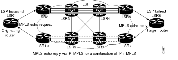
An MPLS echo reply is sent in response to an MPLS echo request. It is sent as an IP packet and forwarded using IP, MPLS, or a combination of both types of switching. The source address of the MPLS echo reply packet is an address from the router generating the echo reply. The destination address is the source address of the router in the MPLS echo request packet.
Figure 1 shows MPLS LSP Ping echo request and echo reply paths.
Figure 1 MPLS LSP Ping Echo Request and Echo Reply Paths
If you initiate an MPLS LSP Ping request at LSR1 to an FEC at LSR6, you get the results shown in Table 1.
Table 1 MPLS LSP Ping Example from Figure 1
1.
LSR1
Initiates an MPLS LSP Ping request for an FEC at the target router LSR6 and sends an MPLS echo request to LSR2.
2.
LSR2
Receives and forwards the MPLS echo request packet through transit routers LSR3 and LSR4 to the penultimate router LSR5.
3.
LSR5
Receives the MPLS echo request, pops the MPLS label, and forwards the packet to LSR6 as an IP packet.
4.
LSR6
Receives the IP packet, processes the MPLS echo request, and sends an MPLS echo reply to LSR1 through an alternate route.
5.
LSR7 to LSR10
Receive and forward the MPLS echo reply back toward LSR1, the originating router.
6.
LSR1
Receives the MPLS echo reply in response to the MPLS echo request.
You can use MPLS LSP Ping to validate IPv4 LDP, AToM, and IPv4 Resource Reservation Protocol (RSVP) FECs by using appropriate keywords and arguments with the ping mpls command:
ping mpls {ipv4 destination-address destination-mask | pseudowire ipv4-address vc-id vc-id
| traffic-eng tunnel-interface tunnel-number}
MPLS LSP Traceroute Operation
MPLS LSP Traceroute also uses MPLS echo request and reply packets to validate an LSP. The echo request and echo reply are UDP packets with source and destination ports set to 3503.
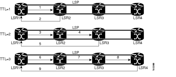
The MPLS LSP Traceroute feature uses time-to-live (TTL) settings to force expiration of the TTL along an LSP. MPLS LSP Traceroute incrementally increases the TTL value in its MPLS echo requests (TTL = 1, 2, 3, 4,...) to discover the downstream mapping of each successive hop. The success of the LSP traceroute depends on the transit router processing the MPLS echo request when it receives a labeled packet with a TTL = 1. On Cisco routers, when the TTL expires, the packet is sent to the Route Processor (RP) for processing. The transit router returns an MPLS echo reply containing information about the transit hop in response to the TTL-expired MPLS packet.
Figure 2 shows an MPLS LSP Traceroute example with an LSP from LSR1 to LSR4.
Figure 2 MPLS LSP Traceroute Example
If you enter an LSP traceroute to a FEC at LSR4 from LSR1, you get the results shown in Table 2.
Table 2 MPLS LSP Traceroute Example Based on Figure 2
1.
LSR1
MPLS echo request—With a target FEC pointing to LSR4 and to a downstream mapping
•
•
2.
LSR2
MPLS echo reply
Receives packet with TTL = 1
•
•
3.
LSR1
MPLS echo request—With the same target FEC and the downstream mapping received in the echo reply from LSR2
•
•
4.
LSR2
MPLS echo request
Receives packet with TTL = 2
•
•
5.
LSR3
MPLS reply packet
Receives packet with TTL = 1
•
•
6.
LSR1
MPLS echo request—With the same target FEC and the downstream mapping received in the echo reply from LSR3
•
•
7.
LSR2
MPLS echo request
Receives packet with TTL = 3
•
•
8.
LSR3
MPLS echo request
Receives packet with TTL = 2
•
•
9.
LSR4
MPLS echo reply
Receives packet with TTL = 1
•
•
•
You can use MPLS LSP Traceroute to validate IPv4 LDP and IPv4 RSVP FECs by using appropriate keywords and arguments with the trace mpls command:
trace mpls {ipv4 destination-address destination-mask | traffic-eng tunnel-interface
tunnel-number}
By default, the TTL is set to 30. Therefore, the traceroute output always contains 30 lines, even if an LSP problem exists. This might mean duplicate entries in the output, should an LSP problem occur. The router address of the last point that the trace reaches is repeated until the ouput is 30 lines. You can ignore the duplicate entries. The following example shows that the trace encountered an LSP problem at the router that has an IP address of 10.6.1.6:
Router# traceroute mpls ipv4 10.6.7.4/32Tracing MPLS Label Switched Path to 10.6.7.4/32, timeout is 2 secondsCodes: '!' - success, 'Q' - request not transmitted,'.' - timeout, 'U' - unreachable,'R' - downstream router but not targetType escape sequence to abort.0 10.6.1.14 MRU 4470 [Labels: 22 Exp: 0]R 1 10.6.1.5 MRU 4470 [Labels: 21 Exp: 0] 2 msR 2 10.6.1.6 4 ms <------ Router address repeated for 2nd to 30th TTL.R 3 10.6.1.6 1 msR 4 10.6.1.6 1 msR 5 10.6.1.6 3 msR 6 10.6.1.6 4 msR 7 10.6.1.6 1 msR 8 10.6.1.6 2 msR 9 10.6.1.6 3 msR 10 10.6.1.6 4 msR 11 10.6.1.6 1 msR 12 10.6.1.6 2 msR 13 10.6.1.6 4 msR 14 10.6.1.6 5 msR 15 10.6.1.6 2 msR 16 10.6.1.6 3 msR 17 10.6.1.6 4 msR 18 10.6.1.6 2 msR 19 10.6.1.6 3 msR 20 10.6.1.6 4 msR 21 10.6.1.6 1 msR 22 10.6.1.6 2 msR 23 10.6.1.6 3 msR 24 10.6.1.6 4 msR 25 10.6.1.6 1 msR 26 10.6.1.6 3 msR 27 10.6.1.6 4 msR 28 10.6.1.6 1 msR 29 10.6.1.6 2 msR 30 10.6.1.6 3 ms <------ TTL 30.If you know the maximum number of hops in your network, you can set the TTL to a smaller value with the trace mpls ttl maximum-time-to-live command. The following example shows the same traceroute command as the previous example, except that this time the TTL is set to 5.
Router# traceroute mpls ipv4 10.6.7.4/32 ttl 5Tracing MPLS Label Switched Path to 10.6.7.4/32, timeout is 2 secondsCodes: '!' - success, 'Q' - request not transmitted,'.' - timeout, 'U' - unreachable,'R' - downstream router but not targetType escape sequence to abort.0 10.6.1.14 MRU 4470 [Labels: 22 Exp: 0]R 1 10.6.1.5 MRU 4474 [No Label] 3 msR 2 10.6.1.6 4 ms <------ Router address repeated for 2nd to 5th TTL.R 3 10.6.1.6 1 msR 4 10.6.1.6 3 msR 5 10.6.1.6 4 msAny Transport over MPLS Virtual Circuit Connection Verification
AToM Virtual Circuit Connection Verification (AToM VCCV) allows the sending of control packets inband of an AToM PW from the originating provider edge (PE) router. The transmission is intercepted at the destination PE router, instead of being forwarded to the customer edge (CE) router. This capability allows you to use MPLS LSP Ping to test the PW section of AToM virtual circuits (VCs).
AToM VCCV consists of the following:
•
•
AToM VCCV Signaling
One of the steps involved in AToM VC setup is the signaling of VC labels and AToM VCCV capabilities between AToM VC endpoints. The router uses an optional parameter, defined in the Internet Draft draft-ieft-pwe3-vccv-01.txt, to communicate the AToM VCCV disposition capabilities of each endpoint.
The AToM VCCV disposition capabilities are categorized as follows:
•
•
Table 3 describes AToM VCCV Type 1 and Type 2 switching modes.
Selection of AToM VCCV Switching Types
Cisco routers always use Type 1 switching, if available, when they send MPLS LSP Ping packets over an AToM VC control channel. Type 2 switching accommodates those VC types and implementations that do not support or interpret the AToM control word.
Table 4 shows the AToM VCCV switching mode advertised and the switching mode selected by the AToM VC.
An AToM VC advertises its AToM VCCV disposition capabilities in both directions: that is, from the originating router (PE1) to the destination router (PE2), and from PE2 to PE1.
In some instances, AToM VCs might use different switching types if the two endpoints have different AToM VCCV capabilities. If PE1 supports Type 1 and Type 2 AToM VCCV switching and PE2 supports only Type 2 AToM VCCV switching, there are two consequences:
•
•
You can determine the AToM VCCV capabilities advertised to and received from the peer by entering the show mpls l2transport binding command at the PE router. For example:
PE1# show mpls l2transport bindingDestination Address: 10.131.191.252, VC ID: 333Local Label: 16Cbit: 1, VC Type: Ethernet, GroupID: 0MTU: 1500, Interface Desc: n/aVCCV Capabilities: Type 1, Type 2Remote Label: 19Cbit: 1, VC Type: Ethernet, GroupID: 0MTU: 1500, Interface Desc: n/aVCCV Capabilities: Type 1MPLS LSP Ping/Traceroute Command Options
MPLS LSP Ping/Traceroute command options are specified as keywords and arguments on the ping mpls and trace mpls commands.
The ping mpls command provides the following options:
ping mpls {ipv4 destination-address destination-mask [destination address-start
address-end increment] [ttl time-to-live] | pseudowire ipv4-address vc-id vc-id
[destination address-start address-end increment] | traffic-eng tunnel-interface
tunnel-number [ttl time-to-live]} [source source-address] [repeat count]
[timeout seconds][{size packet-size} | {sweep minimum maximum size-increment}]
[pad pattern] [reply mode reply-mode] [interval msec] [exp exp-bits] [verbose]
The trace mpls command provides the following options:
trace mpls {ipv4 destination-address destination-mask [destination address-start
address-end address-increment] | traffic-eng tunnel-interface tunnel-number}
[source source-address] [timeout seconds] [reply mode reply-mode]
[ttl maximum-time-to-live] [exp exp-bits]
The following sections describe some command options of the MPLS LSP Ping/Traceroute features:
•
•
•
•
Selection of FECs for Validation
An LSP is formed by labels. Routers learn labels through LDP, TE, AToM, or other MPLS applications. You can use MPLS LSP Ping/Traceroute to validate an LSP used for forwarding traffic for a given FEC. Table 5 lists the keywords and arguments for the ping mpls and traceroute mpls commands that allow the selection of an LSP for validation.
Table 5 Selection of LSPs for Validation
LDP IPv4 prefix
ipv4 destination-address destination-mask
ipv4 destination-address destination-mask
MPLS TE tunnel
traffic-eng tunnel-interface tunnel-number
traffic-eng tunnel-interface tunnel-number
AToM VC
pseudowire ipv4-address vc-id vc-id
—1
1 MPLS LSP Traceroute does not support the AToM tunnel LSP type for this release.
Reply Mode Options for MPLS LSP Ping/Traceroute
The reply mode is used to control how the responding router replies to an MPLS echo request sent by an MPLS LSP Ping or MPLS LSP Traceroute command. Table 6 describes the reply mode options.
On Cisco routers, the reply with an IPv4 UDP packet implies that the router should send an IPv4 UDP packet in reply to an MPLS echo request. If you select the ipv4 reply mode, you do not have explicit control over whether the packet uses IP or MPLS hops to reach the originator of the MPLS echo request. This is the mode that you would normally use to test and verify LSPs.
On Cisco routers, the reply with an IPv4 UDP packet that contains a router alert forces the packet to go back to the destination and be processed by the Route Processor (RP) process switching at each intermediate hop. This bypasses hardware/line card forwarding table inconsistencies. You should select this option when the originating (headend) routers fail to receive a reply to the MPLS echo request.
You can instruct the replying router to send an echo reply with the IP router alert option by using one of the following commands:
ping mpls {ipv4 destination-address destination-mask | pseudowire ipv4-address vc-id vc-id
| traffic-eng tunnel-interface tunnel-number} reply mode router-alert
or
trace mpls {ipv4 destination-address destination-mask | traffic-eng tunnel-interface
tunnel-number} reply mode router-alert
However, the reply with a router alert adds overhead to the process of getting a reply back to the originating router. This method is more expensive to process than a reply without a router alert and should be used only if there are reply failures. That is, the reply with a router alert label should only be used for MPLS LSP Ping or MPLS LSP Traceroute when the originating (headend) router fails to receive a reply to an MPLS echo request.
Packet Handling Along Return Path with an IP/MPLS Router Alert
When an IP packet that contains an IP router alert option in its IP header or an MPLS packet with a router alert label as its outermost label arrives at a router, the router punts (redirects) the packet to the RP process level for handling. This allows these packets to bypass the forwarding failures in hardware routing tables. Table 7 describes how IP and MPLS packets with an IP router alert option are handled by the router switching path processes.
Other MPLS LSP Ping/Traceroute Command Options
Table 8 describes other MPLS LSP Ping/Traceroute command options that can be specified as keywords or arguments with the ping mpls command, or with both the ping mpls and trace mpls commands. Options available for you to use only on the ping mpls command are indicated as such.
MPLS LSP Ping options described in Table 8 can be implemented by the use of the following syntax:
ping mpls {ipv4 destination-address destination-mask [destination address-start
address-end increment] [ttl time-to-live] | pseudowire ipv4-address vc-id vc-id
[destination address-start address-end increment] | traffic-eng tunnel-interface
tunnel-number [ttl time-to-live]} [source source-address] [repeat count]
[{size packet-size} | {sweep minimum maximum size-increment}] [pad pattern]
[timeout seconds] [interval msec] [exp exp-bits] [verbose]
MPLS LSP Traceroute options described in Table 8 can be implemented by the use of the following syntax:
trace mpls {ipv4 destination-address destination-mask [destination address-start
address-end address-increment] | traffic-eng tunnel-interface tunnel-number}
[source source-address] [timeout seconds] [ttl maximum-time-to-live] [exp exp-bits]
MPLS LSP Ping/Traceroute Option Interactions and Loops
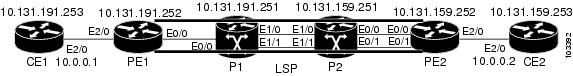
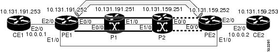
Usage examples for the MPLS Embedded Management—LSP Ping/Traceroute and AToM VCCV feature in this and subsequent sections are based on the sample topology shown in Figure 3.
Figure 3 Sample Topology for Configuration Examples
The interaction of some MPLS Embedded Management—LSP Ping/Traceroute and AToM VCCV options can cause loops. See the following topic for a description of the loops you might encounter with the ping mpls and trace mpls commands:
•
•
Possible Loops with MPLS LSP Ping
With the MPLS LSP Ping feature, loops can occur if you use the repeat count option, the sweep size range option, or the UDP destination address range option.
ping mpls {ipv4 destination-address destination-mask [destination address-start
address-end increment] | pseudowire ipv4-address vc-id vc-id [destination address-start
address-end increment] | traffic-eng tunnel-interface tunnel-number} [repeat count]
[sweep minimum maximum size-increment]
Following is an example of how a loop operates if you use the following keywords and arguments on the ping mpls command:
Router# ping mpls ipv4 10.131.159.251/32 destination 127.0.0.1 127.0.0.2 0.0.0.1 repeat 2
sweep 1450 1475 25Sending 2, [1450..1500]-byte MPLS Echos to 10.131.159.251/32,
timeout is 2 seconds, send interval is 0 msec:
Codes: '!' - success, 'Q' - request not transmitted,
'.' - timeout, 'U' - unreachable,
'R' - downstream router but not target
Type escape sequence to abort.
Destination address 127.0.0.1
!
!
Destination address 127.0.0.2
!
!
Destination address 127.0.0.1
!
!
Destination address 127.0.0.2
!
!
An mpls ping command is sent for each packet size range for each destination address until the end-address is reached. For this example, the loop continues in the same manner until the destination address, 127.0.0.5, is reached. The sequence continues until the number is reached that you specified with the repeat count keyword and argument. For this example, the repeat count is 2. The MPLS LSP Ping loop sequence is as follows:
repeat = 1destination address 1 (address-start)for (size from sweep minimum to maximum, counting by size-increment)send an lsp pingdestination address 2 (address-start + address-increment)for (size from sweep minimum to maximum, counting by size-increment)send an lsp pingdestination address 3 (address-start + address-increment + address-increment)for (size from sweep minimum to maximum, counting by size-increment)send an lsp ping. . .until destination address = address-end. . .until repeat = countPossible Loop with MPLS LSP Traceroute
With the MPLS LSP Traceroute feature, loops can occur if you use the UDP destination address range option and the time-to-live option.
trace mpls {ipv4 destination-address destination-mask [destination address-start
address-end address-increment] | traffic-eng tunnel-interface tunnel-number
[ttl maximum-time-to-live]
Here is an example of how a loop operates if you use the following keywords and arguments on the trace mpls command:
Router# trace mpls ipv4 10.131.159.251/32 destination 127.0.0.1 127.0.0.3 1 ttl 5Tracing MPLS Label Switched Path to 10.131.159.251/32, timeout is 2 secondsCodes: '!' - success, 'Q' - request not transmitted,'.' - timeout, 'U' - unreachable,'R' - downstream router but not targetType escape sequence to abort.Destination address 127.0.0.10 10.131.191.230 MRU 1500 [Labels: 19 Exp: 0]R 1 10.131.159.226 MRU 1504 [implicit-null] 40 ms! 2 10.131.159.225 40 msDestination address 127.0.0.20 10.131.191.230 MRU 1500 [Labels: 19 Exp: 0]R 1 10.131.159.226 MRU 1504 [implicit-null] 40 ms! 2 10.131.159.225 40 msDestination address 127.0.0.30 10.131.191.230 MRU 1500 [Labels: 19 Exp: 0]R 1 10.131.159.226 MRU 1504 [implicit-null] 40 ms! 2 10.131.159.225 48 msAn mpls trace command is sent for each TTL from 1 to the maximum TTL (ttl maximum-time-to-live keyword and argument) for each destination address until the address specified with the destination end-address argument is reached. For this example, the maximum TTL is 5 and the end destination address is 127.0.0.3. The MPLS LSP Traceroute loop sequence is as follows:
destination address 1 (address-start)for (ttl from 1 to maximum-time-to-live)send an lsp tracedestination address 2 (address-start + address-increment)for (ttl from 1 to maximum-time-to-live)send an lsp tracedestination address 3 (address-start + address-increment + address-increment)for (ttl from 1 to maximum-time-to-live)send an lsp trace. . .until destination address = address-endMPLS Echo Request Packets Not Forwarded by IP
MPLS echo request packets sent during an LSP ping are never forwarded by IP. The IP header destination address field in an MPLS echo request packet is a 127.x.y.z/8 address. Routers should not forward packets using a 127.x.y.z/8 address. The 127.x.y.z/8 address corresponds to an address for the local host.
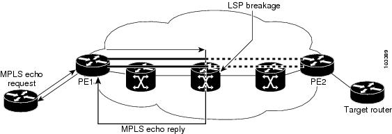
The use of a 127.x.y.z address as a destination address of the UDP packet is significant in that the MPLS echo request packet fails to make it to the target router if a transit router does not label switch the LSP. This allows for the detection of LSP breakages.
•
•
Figure 4 shows the path of the MPLS echo request and reply when a transit router fails to label switch a packet in an LSP.
Figure 4 Path When Transit Router Fails to Label Switch a Packet
Note
Information Provided by the Router Processing LSP Ping or LSP Traceroute
Table 9 describes the characters that the router processing an LSP ping or LSP traceroute packet returns to the sender about the failure or success of the request.
You can also view the return code for an MPLS LSP Ping operation if you enter the verbose keyword on the ping mpls command.
MTU Discovery in an LSP
During an MLPS LSP Ping, MPLS echo request packets are sent with the IP packet attribute set to do not fragment. That is, the DF bit is set in the IP header of the packet. This allows you to use the MPLS echo request to test for the MTU that can be supported for the packet through the LSP without fragmentation.
Figure 5 shows a sample network with a single LSP from PE1 to PE2 formed with labels advertised by means of LDP.
Figure 5 Sample Network with LSP—Labels Advertised by LDP
You can determine the maximum receive unit (MRU) at each hop by tracing the LSP using the MPLS Traceroute feature. The MRU is the maximum size of a labeled packet that can be forwarded through an LSP. The following example shows the results of a trace mpls command when the LSP is formed with labels created by LDP:
PE1# trace mpls ipv4 10.131.159.252/32Tracing MPLS Label Switched Path to 10.131.159.252/32, timeout is 2 secondsCodes: '!' - success, 'Q' - request not transmitted,'.' - timeout, 'U' - unreachable,'R' - downstream router but not targetType escape sequence to abort.0 10.131.191.230 MRU 1496 [Labels: 22/19 Exp: 0/0]R 1 10.131.159.226 MRU 1500 [Labels: 19 Exp: 0] 40 msR 2 10.131.159.229 MRU 1504 [implicit-null] 28 ms! 3 10.131.159.230 40 msYou can determine the MRU for the LSP at each hop through the use of the show forwarding detail command:
PE1# show mpls forwarding 10.131.159.252 detailLocal Outgoing Prefix Bytes tag Outgoing Next Hoptag tag or VC or Tunnel Id switched interface22 19 10.131.159.252/32 0 Tu1 point2pointMAC/Encaps=14/22, MRU=1496, Tag Stack{22 19}, via Et0/0AABBCC009700AABBCC0098008847 0001600000013000No output feature configuredTo determine the maximum sized echo request that will fit on the LSP, you can find the IP MTU by using the show interface interface-name command.
PE1# show interface e0/0Ethernet0/0 is up, line protocol is upHardware is Lance, address is aabb.cc00.9800 (bia aabb.cc00.9800)Internet address is 10.131.191.230/30MTU 1500 bytes, BW 10000 Kbit, DLY 1000 usec, rely 255/255, load 1/255Encapsulation ARPA, loopback not setKeepalive set (10 sec)ARP type: ARPA, ARP Timeout 04:00:00Last input 00:00:01, output 00:00:01, output hang neverLast clearing of "show interface" counters neverInput queue: 0/75/0/0 (size/max/drops/flushes); Total output drops: 0Queueing strategy: fifoOutput queue: 0/40 (size/max)5 minute input rate 0 bits/sec, 0 packets/sec5 minute output rate 0 bits/sec, 0 packets/sec377795 packets input, 33969220 bytes, 0 no bufferReceived 231137 broadcasts, 0 runts, 0 giants, 0 throttles0 input errors, 0 CRC, 0 frame, 0 overrun, 0 ignored0 input packets with dribble condition detected441772 packets output, 40401350 bytes, 0 underruns0 output errors, 0 collisions, 10 interface resets0 babbles, 0 late collision, 0 deferred0 lost carrier, 0 no carrier0 output buffer failures, 0 output buffers swapped outThe IP MTU in the show interface interface-name example is 1500 bytes. Subtract the number of bytes corresponding to the label stack from the MTU number. From the output of the show mpls forwarding command, the Tag stack consists of one label (21). Therefore, the largest MPLS echo request packet that can be sent in the LSP, shown in Figure 5, is 1500 - (2 x 4) = 1492.
You can validate this by using the following mpls ping command:
PE1# ping mpls ipv4 10.131.159.252/32 sweep 1492 1500 1 repeat 1Sending 1, [1492..1500]-byte MPLS Echos to 10.131.159.252/32,timeout is 2 seconds, send interval is 0 msec:Codes: '!' - success, 'Q' - request not transmitted,'.' - timeout, 'U' - unreachable,'R' - downstream router but not targetType escape sequence to abort.!QQQQQQQQSuccess rate is 11 percent (1/9), round-trip min/avg/max = 40/40/40 msIn this command, only packets of 1492 bytes are sent successfully, as indicated by the exclamation point (!). Packets of byte sizes 1493 to 1500 are source-quenched, as indicated by the Q.
You can pad an MPLS echo request so that a payload of a given size can be tested. The pad TLV is useful when you use the MPLS echo request to discover the MTU supportable by an LSP. MTU discovery is extremely important for applications like AToM that contain non-IP payloads that cannot be fragmented.
Managing an LSP Network
To manage an MPLS network you must have the ability to monitor label switched paths (LSPs) and quickly isolate MPLS forwarding problems. You need ways to characterize the liveliness of an LSP and reliably detect when a label switched path fails to deliver user traffic.
You can use MPLS LSP Ping to verify the LSP that is used to transport packets destined for IPv4 LDP prefixes, TE tunnels, and AToM PW FECs. You can use MPLS LSP Traceroute to trace LSPs that are used to carry packets destined for IPv4 LDP prefixes and TE tunnel FECs.
An MPLS echo request is sent through an LSP to validate it. A TTL expiration or LSP breakage causes the transit router to process the echo request before it gets to the intended destination and returns an MPLS echo reply that contains an explanatory reply code to the originator of the echo request.
The successful echo request is processed at the egress of the LSP. The echo reply is sent via an IP path, an MPLS path, or a combination of both back to the originator of the echo request.
Troubleshooting with LSP Ping/Traceroute
ICMP ping and trace commands are often used to help diagnose the root cause of a failure. When an LSP is broken, the packet might make its way to the target router by way of IP forwarding, thus making ICMP ping and traceroute unreliable for detecting MPLS forwarding problems. The MPLS Embedded Management—LSP Ping/Traceroute and AToM VCCV feature extends this diagnostic and troubleshooting ability to the MPLS network and handles inconsistencies between the IP and MPLS forwarding tables, inconsistencies in the MPLS control and data plane, and problems with the reply path.
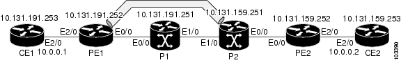
Figure 6 shows a sample topology with an LDP LSP and TE tunnel LSP.
Figure 6 Sample Topology with LDP and TE Tunnel LSPs
This section contains the following topics:
•
•
•
MPLS LSP Ping/Traceroute Discovers LSP Breakage
This section contains the following topics:
•
•
Configuration for Sample Topology
These are sample topology configurations for the troubleshooting examples in the following sections (see Figure 6). There are the six sample router configurations.
Router CE1 Configuration
Following is the configuration for the CE1 router:
version 12.0!hostname ce1!enable password lab!interface Loopback0ip address 10.131.191.253 255.255.255.255no ip directed-broadcast!interface Ethernet2/0ip address 10.0.0.1 255.255.255.0no ip directed-broadcastno keepaliveno cdp enable!endRouter PE1 Configuration
Following is the configuration for the PE1 router:
version 12.0!hostname pe1!ip cefmpls label protocol ldpmpls traffic-eng tunnelsno mpls traffic-eng auto-bw timers frequency 0mpls ldp discovery targeted-hello accept!interface Loopback0ip address 10.131.191.252 255.255.255.255no ip directed-broadcast!interface Tunnel1ip unnumbered Loopback0no ip directed-broadcastmpls label protocol ldpmpls iptunnel destination 10.131.159.251tunnel mode mpls traffic-engtunnel mpls traffic-eng autoroute announcetunnel mpls traffic-eng priority 2 2tunnel mpls traffic-eng bandwidth 512tunnel mpls traffic-eng path-option 1 dynamic!interface Tunnel2ip unnumbered Loopback0no ip directed-broadcastshutdownmpls label protocol ldpmpls iptunnel destination 10.131.159.252tunnel mode mpls traffic-engtunnel mpls traffic-eng autoroute announcetunnel mpls traffic-eng priority 1 1tunnel mpls traffic-eng bandwidth 100tunnel mpls traffic-eng path-option 1 dynamic!interface Ethernet0/0ip address 10.131.191.230 255.255.255.252no ip directed-broadcastmpls traffic-eng tunnelsmpls ipip rsvp bandwidth 1500 1500ip rsvp signalling dscp 0!interface Ethernet1/0ip address 10.131.159.246 255.255.255.252no ip directed-broadcastno shutdownmpls ipip rsvp bandwidth 1500 1500ip rsvp signalling dscp 0!interface Ethernet2/0no ip addressno ip directed-broadcastno cdp enablexconnect 10.131.159.252 333 encapsulation mpls!interface Ethernet3/0no ip addressno ip directed-broadcastshutdown!router ospf 1log-adjacency-changespassive-interface Loopback0network 10.131.159.244 0.0.0.3 area 0network 10.131.191.228 0.0.0.3 area 0network 10.131.191.232 0.0.0.3 area 0network 10.131.191.252 0.0.0.0 area 0mpls traffic-eng router-id Loopback0mpls traffic-eng area 0!ip classlessendRouter P1 Configuration
Following is the configuration for the P1 router:
version 12.0service timestamps debug datetime msecservice timestamps log datetime msecno service password-encryption!hostname p1!enable password lab!ip cefmpls label protocol ldpmpls ldp logging neighbor-changesmpls traffic-eng tunnelsno mpls traffic-eng auto-bw timers frequency 0mpls ldp discovery targeted-hello accept!interface Loopback0ip address 10.131.191.251 255.255.255.255no ip directed-broadcast!interface Ethernet0/0ip address 10.131.191.229 255.255.255.252no ip directed-broadcastmpls traffic-eng tunnelsmpls ipip rsvp bandwidth 1500 1500ip rsvp signalling dscp 0!interface Ethernet1/0ip address 10.131.159.226 255.255.255.252no ip directed-broadcastmpls traffic-eng tunnelsmpls ipip rsvp bandwidth 1500 1500ip rsvp signalling dscp 0!router ospf 1log-adjacency-changespassive-interface Loopback0network 10.131.159.224 0.0.0.3 area 0network 10.131.191.228 0.0.0.3 area 0network 10.131.191.251 0.0.0.0 area 0mpls traffic-eng router-id Loopback0mpls traffic-eng area 0!endRouter P2 Configuration
Following is the configuration for the P2 router:
version 12.0hostname p2!ip cefmpls label protocol ldpmpls ldp logging neighbor-changesmpls traffic-eng tunnelsno mpls traffic-eng auto-bw timers frequency 0mpls ldp discovery directed-hello accept!!interface Loopback0ip address 10.131.159.251 255.255.255.255no ip directed-broadcast!interface Ethernet0/0ip address 10.131.159.229 255.255.255.252no ip directed-broadcastmpls traffic-eng tunnelsmpls ipip rsvp bandwidth 1500 1500ip rsvp signalling dscp 0!interface Ethernet1/0ip address 10.131.159.225 255.255.255.252no ip directed-broadcastmpls traffic-eng tunnelsmpls ipip rsvp bandwidth 1500 1500ip rsvp signalling dscp 0!router ospf 1log-adjacency-changespassive-interface Loopback0network 10.131.159.224 0.0.0.3 area 0network 10.131.159.228 0.0.0.3 area 0network 10.131.159.251 0.0.0.0 area 0mpls traffic-eng router-id Loopback0mpls traffic-eng area 0!endRouter PE2 Configuration
Following is the configuration for the PE2 router:
version 12.0service timestamps debug datetime msecservice timestamps log datetime msecno service password-encryption!hostname as2_pe!logging snmp-authfailenable password lab!clock timezone EST -5ip subnet-zeroip cefno ip domain-lookupmpls label protocol ldpmpls ldp logging neighbor-changesmpls ldp explicit-nullmpls traffic-eng tunnelsno mpls traffic-eng auto-bw timers frequency 0tag-switching tdp discovery directed-hello acceptframe-relay switching!!interface Loopback0ip address 10.131.159.252 255.255.255.255no ip directed-broadcast!interface Tunnel0ip unnumbered Loopback0no ip directed-broadcasttunnel destination 10.131.191.252tunnel mode mpls traffic-engtunnel mpls traffic-eng path-option 5 explicit name as1pe-long-path!interface Ethernet0/0ip address 10.131.159.230 255.255.255.252no ip directed-broadcastmpls traffic-eng tunnelstag-switching ipip rsvp bandwidth 1500 1500ip rsvp signalling dscp 0!interface Ethernet1/0ip address 10.131.159.245 255.255.255.252no ip directed-broadcastmpls traffic-eng tunnelstag-switching ipip rsvp bandwidth 1500 1500ip rsvp signalling dscp 0!interface Ethernet2/0no ip addressno ip directed-broadcastno cdp enablexconnect 10.131.191.252 333 encapsulation mpls!interface Ethernet3/0no ip addressno ip directed-broadcast!interface Serial4/0no ip addressno ip directed-broadcastshutdown!interface Serial5/0no ip addressno ip directed-broadcastshutdown!router ospf 1mpls traffic-eng router-id Loopback0mpls traffic-eng area 0log-adjacency-changespassive-interface Loopback0network 10.131.122.0 0.0.0.3 area 0network 10.131.159.228 0.0.0.3 area 0network 10.131.159.232 0.0.0.3 area 0network 10.131.159.244 0.0.0.3 area 0network 10.131.159.252 0.0.0.0 area 0!ip classless!!ip explicit-path name as1pe-long-path enablenext-address 10.131.159.229next-address 10.131.159.226next-address 10.131.191.230!!line con 0exec-timeout 0 0line aux 0line vty 0 4exec-timeout 0 0password lablogin!endRouter CE2 Configuration
Following is the configuration for the CE2 router:
version 12.0!hostname ce2!enable password lab!interface Loopback0ip address 10.131.159.253 255.255.255.255no ip directed-broadcast!interface Ethernet2/0ip address 10.0.0.2 255.255.255.0no ip directed-broadcastno keepaliveno cdp enable!endVerifying That the LSP Is Set Up Correctly
A show mpls forwarding-table command shows that tunnel 1 is in the MPLS forwarding table.
PE1# show mpls forwarding-table 10.131.159.252Local Outgoing Prefix Bytes tag Outgoing Next Hoptag tag or VC or Tunnel Id switched interface22 19 [T] 10.131.159.252/32 0 Tu1 point2point[T] Forwarding through a TSP tunnel.View additional tagging info with the 'detail' optionA show mpls traffic-eng tunnels tunnel 1 command entered at PE1 displays information about tunnel 1 and verifies that it is forwarding packets with an out label of 22.
PE1# show mpls traffic-eng tunnels tunnel 1Name: PE1_t1 (Tunnel1) Destination: 10.131.159.251Status:Admin: up Oper: up Path: valid Signalling: connectedpath option 1, type dynamic (Basis for Setup, path weight 20)Config Parameters:Bandwidth: 512 kbps (Global) Priority: 2 2 Affinity: 0x0/0xFFFFMetric Type: TE (default)AutoRoute: enabled LockDown: disabled Loadshare: 512 bw-basedauto-bw: disabledActive Path Option Parameters:State: dynamic path option 1 is activeBandwidthOverride: disabled LockDown: disabled Verbatim: disabledInLabel : -OutLabel : Ethernet0/0, 22RSVP Signalling Info:Src 10.131.191.252, Dst 10.131.159.251, Tun_Id 1, Tun_Instance 28RSVP Path Info:My Address: 10.131.191.230Explicit Route: 10.131.191.229 10.131.159.226 10.131.159.225 10.131.159.251Record Route: NONETspec: ave rate=512 kbits, burst=1000 bytes, peak rate=512 kbitsRSVP Resv Info:Record Route: NONEFspec: ave rate=512 kbits, burst=1000 bytes, peak rate=512 kbitsShortest Unconstrained Path Info:Path Weight: 20 (TE)Explicit Route: 10.131.191.230 10.131.191.229 10.131.159.226 10.131.159.22510.131.159.251History:Tunnel:Time since created: 9 days, 14 hours, 12 minutesTime since path change: 2 minutes, 18 secondsCurrent LSP:Uptime: 2 minutes, 18 secondsPrior LSP:ID: path option 1 [3]Removal Trigger: tunnel shutdownA trace mpls command issued at PE1 verifies that packets with 22 as the outermost label and 19 as the end of stack label are forwarded from PE1 to PE2.
PE1# trace mpls ipv4 10.131.159.252/32Tracing MPLS Label Switched Path to 10.131.159.252/32, timeout is 2 secondsCodes: '!' - success, 'Q' - request not transmitted,'.' - timeout, 'U' - unreachable,'R' - downstream router but not targetType escape sequence to abort.0 10.131.191.230 MRU 1496 [Labels: 22/19 Exp: 0/0]R 1 10.131.159.226 MRU 1504 [Labels: 19 Exp: 0] 40 msR 2 10.131.159.229 MRU 1504 [implicit-null] 28 ms! 3 10.131.159.230 40 msThe MPLS LSP Traceroute to PE2 is successful, as indicated by the exclamation point (!).
Discovering LSP Breakage
An LDP target-session is established between routers PE1 and P2, as shown in the output of the following show mpls ldp discovery command:
PE1# show mpls ldp discoveryLocal LDP Identifier:10.131.191.252:0Discovery Sources:Interfaces:Ethernet0/0 (ldp): xmit/recvLDP Id: 10.131.191.251:0Tunnel1 (ldp): Targeted -> 10.131.159.251Targeted Hellos:10.131.191.252 -> 10.131.159.252 (ldp): active/passive, xmit/recvLDP Id: 10.131.159.252:010.131.191.252 -> 10.131.159.251 (ldp): active, xmit/recvLDP Id: 10.131.159.251:0Enter the following command on the P2 router in global configuration mode:
P2(config)# no mpls ldp discovery targeted-hello acceptThe LDP configuration change causes the targeted LDP session between the headend and tailend of the TE tunnel to go down. Labels for IPv4 prefixes learned by P2 are not advertised to PE1. Thus, all IP prefixes reachable by P2 are reachable by PE1 only through IP (not MPLS). In other words, packets destined for those prefixes through Tunnel 1 at PE1 will be IP switched at P2 (which is undesirable).
The following show mpls ldp discovery command shows that the LDP targeted-session is down:
PE1# show mpls ldp discoveryLocal LDP Identifier:10.131.191.252:0Discovery Sources:Interfaces:Ethernet0/0 (ldp): xmit/recvLDP Id: 10.131.191.251:0Tunnel1 (ldp): Targeted -> 10.131.159.251Targeted Hellos:10.131.191.252 -> 10.131.159.252 (ldp): active/passive, xmit/recvLDP Id: 10.131.159.252:010.131.191.252 -> 10.131.159.251 (ldp): active, xmitEnter the show mpls forwarding-table command at the PE1 router. The display shows that the outgoing packets are untagged as a result of the LDP configuration changes.
PE1# show mpls forwarding-table 10.131.159.252Local Outgoing Prefix Bytes tag Outgoing Next Hoptag tag or VC or Tunnel Id switched interface22 Untagged[T] 10.131.159.252/32 0 Tu1 point2point[T] Forwarding through a TSP tunnel.View additional tagging info with the 'detail' optionA ping mpls command entered at the PE1 router displays the following:
PE1# ping mpls ipv4 10.131.159.252/32 repeat 1Sending 1, 100-byte MPLS Echos to 10.131.159.252/32,timeout is 2 seconds, send interval is 0 msec:Codes: '!' - success, 'Q' - request not transmitted,'.' - timeout, 'U' - unreachable,'R' - downstream router but not targetType escape sequence to abort.RSuccess rate is 0 percent (0/1)The ping mpls command fails. The R indicates that the sender of the MPLS echo reply had a routing entry but no MPLS FEC. Entering the verbose keyword to the ping mpls command displays the MPLS LSP echo reply sender address and the return code. You should be able to solve the problem by Telneting to the replying router and inspecting its forwarding and label tables. You might need to look at the neighboring upstream router as well, because the breakage might be on the upstream router.
PE1# ping mpls ipv4 10.131.159.252/32 repeat 1 verboseSending 1, 100-byte MPLS Echos to 10.131.159.252/32,timeout is 2 seconds, send interval is 0 msec:Codes: '!' - success, 'Q' - request not transmitted,'.' - timeout, 'U' - unreachable,'R' - downstream router but not targetType escape sequence to abort.R 10.131.159.225, return code 6Success rate is 0 percent (0/1)Alternatively, use the LSP traceroute command to figure out which router caused the breakage. In the following example, for subsequent values of TTL greater than 2, the same router keeps responding (10.131.159.225). This suggests that the MPLS echo request keeps getting processed by the router regardless of the TTL. Inspection of the label stack shows that P1 pops the last label and forwards the packet to P2 as an IP packet. This explains why the packet keeps getting processed by P2. MPLS echo request packets cannot be forwarded by use of the destination address in the IP header because the address is set to a 127/8 address.
PE1# trace mpls ipv4 10.131.159.252/32 ttl 5Tracing MPLS Label Switched Path to 10.131.159.252/32, timeout is 2 secondsCodes: '!' - success, 'Q' - request not transmitted,'.' - timeout, 'U' - unreachable,'R' - downstream router but not targetType escape sequence to abort.0 10.131.191.230 MRU 1500 [Labels: 22 Exp: 0]R 1 10.131.159.226 MRU 1504 [implicit-null] 40 msR 2 10.131.159.225 40 msR 3 10.131.159.225 40 msR 4 10.131.159.225 40 msR 5 10.131.159.225 40 msMPLS LSP Traceroute Tracks Untagged Cases
This troubleshooting section contains examples of how to use MPLS LSP Traceroute to determine potential issues with packets that are tagged as implicit null and packets that are untagged.
•
•
Untagged output interfaces at a penultimate hop do not impact the forwarding of IP packets through an LSP because the forwarding decision is made at the penultimate hop through use of the incoming label. The untagged case causes AToM and MPLS VPN traffic to be dropped at the penultimate hop.
Troubleshooting Implicit Null Cases
In the following example, Tunnel 1 is shut down, and only an LSP formed with LDP labels is established. An implicit null is advertised between the P2 and PE2 routers. Entering an MPLS LSP Traceroute at the PE1 router results in the following display:
PE1# trace mpls ipv4 10.131.159.252/32Tracing MPLS Label Switched Path to 10.131.159.252/32, timeout is 2 secondsCodes: '!' - success, 'Q' - request not transmitted,'.' - timeout, 'U' - unreachable,'R' - downstream router but not targetType escape sequence to abort.0 10.131.191.230 MRU 1500 [Labels: 20 Exp: 0]R 1 10.131.159.226 MRU 1500 [Labels: 19 Exp: 0] 80 msR 2 10.131.159.229 MRU 1504 [implicit-null] 28 ms! 3 10.131.159.230 40 msThis output shows that packets are forwarded from P2 to PE2 with an implicit-null label. Address 10.131.159.229 is configured for the P2 Ethernet 0/0 out interface for the PE2 router.
Troubleshooting Untagged Cases
Untagged cases are valid configurations for IGP LSPs that could cause problems for MPLS VPNs.
A show mpls forwarding-table command and a show mpls ldp discovery command issued at the P2 router show that LDP is properly set up:
P2# show mpls for 10.131.159.252Local Outgoing Prefix Bytes tag Outgoing Next Hoptag tag or VC or Tunnel Id switched interface19 Pop tag 10.131.159.252/32 0 Et0/0 10.131.159.230P2# show mpls ldp discoveryLocal LDP Identifier:10.131.159.251:0Discovery Sources:Interfaces:Ethernet0/0 (ldp): xmit/recvLDP Id: 10.131.159.252:0Ethernet1/0 (ldp): xmit/recvLDP Id: 10.131.191.251:0The show mpls ldp discovery command output shows that Ethernet0/0, which connects PE2 to P2, is sending and receiving packets.
If a no mpls ip command is entered on Ethernet 0/0, this could prevent an LDP session between the P2 and PE2 routers from being established. A show mpls ldp discovery command entered on the PE router shows that the MPLS LDP session with the PE2 router is down:
P2# show mpls ldp discoveryLocal LDP Identifier:10.131.159.251:0Discovery Sources:Interfaces:Ethernet0/0 (ldp): xmitEthernet1/0 (ldp): xmit/recvLDP Id: 10.131.191.251:0If the MPLS LDP session to PE2 goes down, the LSP to 10.131.159.252 becomes untagged, as shown by the show mpls forwarding-table command:
P2# show mpls forwarding-table 10.131.159.252Local Outgoing Prefix Bytes tag Outgoing Next Hoptag tag or VC or Tunnel Id switched interface19 Untagged 10.131.159.252/32 864 Et0/0 10.131.159.230Untagged cases would provide an MPLS LSP Traceroute reply with packets tagged with No Label, as shown in the following display:
PE1# trace mpls ipv4 10.131.159.252/32Tracing MPLS Label Switched Path to 10.131.159.252/32, timeout is 2 secondsCodes: '!' - success, 'Q' - request not transmitted,'.' - timeout, 'U' - unreachable,'R' - downstream router but not targetType escape sequence to abort.0 10.131.191.230 MRU 1500 [Labels: 20 Exp: 0]R 1 10.131.159.226 MRU 1500 [Labels: 19 Exp: 0] 80 msR 2 10.131.159.229 MRU 1504 [No Label] 28 ms! 3 10.131.159.230 40 msMPLS LSP Ping/Traceroute Returns a Q
The Q return code always means that the packet could not be transmitted. The problem can be caused by insufficient memory, but it probably results because an LSP could not be found that matches the FEC information that was entered on the command line.
The reason that the packet was not forwarded needs to be determined. To do so, look at the Routing Information Base (RIB), the forwarding information base (FIB), the label information base (LIB), and the MPLS label forwarding information base (LFIB). Lack of an entry for the FEC in any one of these routing/forwarding bases would return a Q.
Table 10 lists commands you can use for troubleshooting when the MPLS echo reply returns a Q.
Table 10 Troubleshooting a Q
Routing Information Base
show ip route
Label information base/MPLS forwarding information base
show mpls forwarding-table detail
The following example shows a ping mpls command where the MPLS echo request is not transmitted, as shown by the returned Qs:
PE1# ping mpls ipv4 10.0.0.1/32Sending 5, 100-byte MPLS Echos to 10.0.0.1/32,timeout is 2 seconds, send interval is 0 msec:Codes: '!' - success, 'Q' - request not transmitted,'.' - timeout, 'U' - unreachable,'R' - downstream router but not targetType escape sequence to abort.QQQQQSuccess rate is 0 percent (0/5)A show mpls forwarding-table command and show ip route command demonstrate that the address is not in either routing table:
PE1# show mpls forwarding-table 10.0.0.1Local Outgoing Prefix Bytes tag Outgoing Next Hoptag tag or VC or Tunnel Id switched interfacePE1# show ip route 10.0.0.1% Subnet not in tableThe MPLS echo request is not transmitted because the IPv4 address (10.0.0.1) is not found in either the LFIB or the RIB routing table.
Load Balancing for IPv4 LDP LSPs
An ICMP ping or trace follows one path from the originating router to the target router. Round robin load balancing of IP packets from a source router is used to discover the various output paths to the target IP address.
For MPLS LSP Ping/Traceroute, Cisco routers use the source and destination addresses in the IP header for load balancing when multiple paths exist through the network to a target router. The Cisco implementation of MPLS might check the destination address of an IP payload to accomplish load balancing (this checking depends on the platform).
To check for load balancing paths, you use the 127.z.y.x/8 destination address in the ping mpls ipv4 ip-address address-mask destination address-start address-end address-increment command. The following examples show that different paths are followed to the same destination. This demonstrates that load balancing occurs between the originating router and the target router.
To ensure that the Ethernet 1/0 interface on the PE1 router is operational, you enter the following commands on the PE1 router:
PE1# configure terminalEnter configuration commands, one per line. End with CNTL/Z.PE1(config)# interface ethernet 1/0PE1(config-if)# no shutPE1(config-if)# end*Dec 31 19:14:10.034: %LINK-3-UPDOWN: Interface Ethernet1/0, changed state to up*Dec 31 19:14:11.054: %LINEPROTO-5-UPDOWN: Line protocol on Interface Ethernet1/0, changed state to upendPE1#*Dec 31 19:14:12.574: %SYS-5-CONFIG_I: Configured from console by console*Dec 31 19:14:19.334: %OSPF-5-ADJCHG: Process 1, Nbr 10.131.159.252 on Ethernet1/0 from LOADING to FULL, Loading DonePE1#The following show mpls forwarding-table command displays the possible outgoing interfaces and next hops for the prefix 10.131.159.251/32:
PE1# show mpls forwarding-table 10.131.159.251Local Outgoing Prefix Bytes tag Outgoing Next Hoptag tag or VC or Tunnel Id switched interface21 19 10.131.159.251/32 0 Et0/0 10.131.191.22920 10.131.159.251/32 0 Et1/0 10.131.159.245The following ping mpls command to 10.131.159.251/32 with a destination UDP address of 127.0.0.1 shows that the path selected has a path index of 0:
Router# ping mpls ipv4 10.131.159.251/32 destination 127.0.0.1 repeat 1Sending 1, 100-byte MPLS Echos to 10.131.159.251/32,timeout is 2 seconds, send interval is 0 msec:Codes: '!' - success, 'Q' - request not transmitted,'.' - timeout, 'U' - unreachable,'R' - downstream router but not targetType escape sequence to abort.!Success rate is 100 percent (1/1), round-trip min/avg/max = 40/40/40 msPE1#*Dec 29 20:42:40.638: LSPV: Echo Request sent on IPV4 LSP, load_index 2, pathindex 0, size 100*Dec 29 20:42:40.638: 46 00 00 64 00 00 40 00 FF 11 9D 03 0A 83 BF FC*Dec 29 20:42:40.638: 7F 00 00 01 94 04 00 00 0D AF 0D AF 00 4C 14 70*Dec 29 20:42:40.638: 00 01 00 00 01 02 00 00 1A 00 00 1C 00 00 00 01*Dec 29 20:42:40.638: C3 9B 10 40 A3 6C 08 D4 00 00 00 00 00 00 00 00*Dec 29 20:42:40.638: 00 01 00 09 00 01 00 05 0A 83 9F FB 20 00 03 00*Dec 29 20:42:40.638: 13 01 AB CD AB CD AB CD AB CD AB CD AB CD AB CD*Dec 29 20:42:40.638: AB CD AB CD*Dec 29 20:42:40.678: LSPV: Echo packet received: src 10.131.159.225, dst 10.131.191.252, size 74*Dec 29 20:42:40.678: AA BB CC 00 98 01 AA BB CC 00 FC 01 08 00 45 C0*Dec 29 20:42:40.678: 00 3C 32 D6 00 00 FD 11 15 37 0A 83 9F E1 0A 83*Dec 29 20:42:40.678: BF FC 0D AF 0D AF 00 28 D1 85 00 01 00 00 02 02*Dec 29 20:42:40.678: 03 00 1A 00 00 1C 00 00 00 01 C3 9B 10 40 A3 6C*Dec 29 20:42:40.678: 08 D4 C3 9B 10 40 66 F5 C3 C8The following ping mpls command to 10.131.159.251/32 with a destination UDP address of 127.0.0.3 shows that the path selected has a path index of 1:
PE1# ping mpls ipv4 10.131.159.251/32 dest 127.0.0.3 repeat 1Sending 1, 100-byte MPLS Echos to 10.131.159.251/32,timeout is 2 seconds, send interval is 0 msec:Codes: '!' - success, 'Q' - request not transmitted,'.' - timeout, 'U' - unreachable,'R' - downstream router but not targetType escape sequence to abort.!Success rate is 100 percent (1/1), round-trip min/avg/max = 40/40/40 msPE1#*Dec 29 20:43:09.518: LSPV: Echo Request sent on IPV4 LSP, load_index 13, pathindex 1, size 100*Dec 29 20:43:09.518: 46 00 00 64 00 00 40 00 FF 11 9D 01 0A 83 BF FC*Dec 29 20:43:09.518: 7F 00 00 03 94 04 00 00 0D AF 0D AF 00 4C 88 58*Dec 29 20:43:09.518: 00 01 00 00 01 02 00 00 38 00 00 1D 00 00 00 01*Dec 29 20:43:09.518: C3 9B 10 5D 84 B3 95 84 00 00 00 00 00 00 00 00*Dec 29 20:43:09.518: 00 01 00 09 00 01 00 05 0A 83 9F FB 20 00 03 00*Dec 29 20:43:09.518: 13 01 AB CD AB CD AB CD AB CD AB CD AB CD AB CD*Dec 29 20:43:09.518: AB CD AB CD*Dec 29 20:43:09.558: LSPV: Echo packet received: src 10.131.159.229, dst 10.131.191.252, size 74*Dec 29 20:43:09.558: AA BB CC 00 98 01 AA BB CC 00 FC 01 08 00 45 C0*Dec 29 20:43:09.558: 00 3C 32 E9 00 00 FD 11 15 20 0A 83 9F E5 0A 83*Dec 29 20:43:09.558: BF FC 0D AF 0D AF 00 28 D7 57 00 01 00 00 02 02*Dec 29 20:43:09.558: 03 00 38 00 00 1D 00 00 00 01 C3 9B 10 5D 84 B3*Dec 29 20:43:09.558: 95 84 C3 9B 10 5D 48 3D 50 78To see the actual path chosen, you use the debug mpls lspv packet data command.
Note
Additional References
The following sections provide references related to the MPLS Embedded Management—LSP Ping/Traceroute and AToM VCCV feature.
•
•
Related Documents
Usage examples for the IP ping and IP traceroute commands
Usage examples for the extended ping and extended traceroute commands
Configuration and verification tasks for MPLS LDP
Configuration task for MPLS traffic engineering
Configuration and verification tasks for AToM
Troubleshooting procedures for MPLS
Switching services commands
Cisco IOS Switching Services Command Reference, Release 12.3
Configuration and verification tasks for MPLS applications
Part 3: Multiprotocol Label Switching, Cisco IOS Switching Services Configuration Guide, Release 12.3
Standards
No new or modified standards are supported by this feature, and support for existing standards has not been modified by this feature.
—
MIBs
RFCs
Technical Assistance
Command Reference
This section documents only new and modified commands.
debug mpls lspv
To display information related to the Multiprotocol Label Switching (MPLS) Label Switched Path (LSP) Ping/Traceroute feature, use the debug mpls lspv command in privileged EXEC mode. To disable debugging output, use the no form of this command.
debug mpls lspv [tlv] [error] [event] [packet [data | error]]
no debug mpls lspv
Syntax Description
tlv
(Optional) Displays MPLS echo packet type-length-value (TLV) information as it is being coded and decoded.
error
(Optional) Displays error conditions encountered during MPLS echo request and echo reply encoding and decoding. See Table 11.
event
(Optional) Displays MPLS echo request and reply send and receive event information.
packet data
(Optional) Displays detailed debug information for the MPLS echo packets sent and received. This output is seen only on the originating router and the router generating the reply.
packet error
(Optional) Displays packet errors for MPLS echo request and reply. No output is expected for this command at this time.
Defaults
MPLS LSP debugging is disabled.
Command Modes
Privileged EXEC
Command History
Usage Guidelines
Use this command to monitor activity associated with the ping mpls and the trace mpls commands.
Table 11 lists the messages displayed by the debug mpls lspv error command and the reason for the error message.
Examples
The following example shows the syntax for the debug mpls lspv command:
PE1_Router# debug mpls lspv ?error error debuggingevent event debuggingpacket packet debug optionstlv TLV debuggingThe following example shows sample output for the ping mpls command when LSPV event debugging is enabled:
PE1_Router# debug mpls lspv eventLSPV event debugging is onPE1_Router#ping mpls ipv4 10.131.159.252/32 repeat 1Sending 1, 100-byte MPLS Echos to 10.131.159.252/32,timeout is 2 seconds, send interval is 0 msec:Codes: '!' - success, 'Q' - request not transmitted,'.' - timeout, 'U' - unreachable,'R' - downstream router but not targetType escape sequence to abort.!Success rate is 100 percent (1/1), round-trip min/avg/max = 48/48/48 msPE1_Router#*Dec 31 19:31:15.366: LSPV:waiting for 2 seconds*Dec 31 19:31:15.366: LSPV: sender_handle: 2000002D, Event Echo Requests Start, [Idle->Waiting for Echo Reply]*Dec 31 19:31:15.414: LSPV: sender_handle: 2000002D, Event Echo Reply Received, [Waiting for Echo Reply->Waiting for Interval]*Dec 31 19:31:15.466: LSPV: sender_handle: 2000002D, Event Echo Requests Cancel, [Waiting for Interval->Idle]PE1_Router# undebug allAll possible debugging has been turned offThe following example shows sample output for the ping mpls command when LSPV TLV debugging is enabled:
PE1_Router# debug mpls lspv tlvLSPV tlv debugging is onPE1_Router# ping mpls ipv4 10.131.159.252/32 repeat 1Sending 1, 100-byte MPLS Echos to 10.131.159.252/32,timeout is 2 seconds, send interval is 0 msec:Codes: '!' - success, 'Q' - request not transmitted,'.' - timeout, 'U' - unreachable,'R' - downstream router but not targetType escape sequence to abort.!Success rate is 100 percent (1/1), round-trip min/avg/max = 40/40/40 msPE1_Router#*Dec 31 19:32:32.566: LSPV: Echo Hdr encode: version 1, msg type 1, reply mode 2 , return_code 0, return_subcode 0, sender handle 9400002E, sequence number 1, timestamp sent 14:32:32 EST Wed Dec 31 2003, timestamp rcvd 19:00:00 EST Thu Dec 31 1899*Dec 31 19:32:32.566: LSPV: IPV4 FEC encode: destaddr 10.131.159.252/32*Dec 31 19:32:32.566: LSPV: Pad TLV encode: type 1, size 18, pattern 0xABCD*Dec 31 19:32:32.606: LSPV: Echo Hdr decode: version 1, msg type 2, reply mode 2, return_code 3, return_subcode 0, sender handle 9400002E, sequence number 1, timestamp sent 14:32:32 EST Wed Dec 31 2003, timestamp rcvd 14:32:32 EST Wed Dec 31 2003PE1_Router# undebug allAll possible debugging has been turned offRelated Commands
Checks MPLS LSP connectivity.
Discovers MPLS LSP routes that packets will actually take when traveling to their destinations.
ping mpls
To check Multiprotocol Label Switching (MPLS) label switched path (LSP) connectivity, use the ping mpls command in privileged EXEC mode.
ping mpls {ipv4 destination-address destination-mask [destination address-start address-end
increment] [ttl time-to-live] | pseudowire ipv4-address vc-id vc-id [destination address-start
address-end increment] | traffic-eng tunnel-interface tunnel-number [ttl time-to-live]} [source
source-address] [repeat count] [timeout seconds] [{size packet-size} | {sweep minimum
maximum size-increment}] [pad pattern] [reply mode reply-mode] [interval msec] [exp
exp-bits] [verbose]Syntax Description
Defaults
repeat count = 1
timeout = 2 seconds
packet size = 100 bytes
sweep minimum = 100 bytes
sweep maximum = 17986 bytes
sweep size increment = 100 bytes
pad TLV pattern = 0xABCD
reply mode = ipv4 via UDP (2)
time-to-live = 255 seconds
send interval = 0 msec
exp bits in MPLS header = 0
verbose = noCommand Modes
Privileged EXEC
Command History
Usage Guidelines
Use the mpls ping command to validate, test, or troubleshoot IPv4 LDP LSPs, IPv4 RSVP TE tunnels, and AToM VCs.
Examples
The following example shows how to use the ping mpls command to test connectivity of an IPv4 LDP LSP:
PE# ping mpls ipv4 10.131.191.252/32 exp 5 repeat 5 verboseSending 5, 100-byte MPLS Echos to 10.131.191.252, timeout is 2 seconds:Codes: '!' - success, 'Q' - request not transmitted,'.' - timeout, 'U' - unreachable,'R' - downstream router but not destinationType escape sequence to abort.! 10.131.191.230, return code 3! 10.131.191.230, return code 3! 10.131.191.230, return code 3! 10.131.191.230, return code 3! 10.131.191.230, return code 3Success rate is 100 percent (5/5), round-trip min/avg/max = 100/102/112 msThe following example shows how to invoke the ping mpls command in the interactive mode:
PE1# pingProtocol [ip]: mplsTarget IPv4, pseudowire or traffic-eng [ipv4]: ipv4Target IPv4 address: 10.131.159.252Target mask: 255.255.255.255Repeat count [5]: 1Datagram size [100]:Timeout in seconds [2]:Send interval in msec [0]:Extended commands? [no]: yesDestination address or destination start address: 127.0.0.1Destination end address: 127.0.0.3Destination address increment: 0.0.0.1Source address:EXP bits in mpls header [0]:Pad TLV pattern [ABCD]:Time To Live [255]:Reply mode ( 2-ipv4 via udp, 3-ipv4 via udp with router alert) [2]:Verbose mode? [no]: yesSweep range of sizes? [no]:Sending 1, 100-byte MPLS Echos to 10.131.159.252/32,timeout is 2 seconds, send interval is 0 msec:Codes: '!' - success, 'Q' - request not transmitted,'.' - timeout, 'U' - unreachable,'R' - downstream router but not targetType escape sequence to abort.Destination address 127.0.0.1! 10.131.159.245, return code 3Destination address 127.0.0.2! 10.131.159.245, return code 3Destination address 127.0.0.3! 10.131.159.245, return code 3Success rate is 100 percent (3/3), round-trip min/avg/max = 40/48/52 ms
Note
The following example shows how to use the ping mpls command to test connectivity of an AToM VC:
PE# show mpls l2transport vcLocal intf Local circuit Dest address VC ID Status------------- ----------------------- --------------- ---------- ----------Et2/0 Ethernet 10.131.191.252 333 UPas2_pe#sh mpls l2transport vc detLocal interface: Et2/0 up, line protocol up, Ethernet upDestination address: 10.131.191.252, VC ID: 333, VC status: upPreferred path: not configuredDefault path: activeTunnel label: imp-null, next hop 10.131.159.246Output interface: Et1/0, imposed label stack {16}Create time: 06:46:08, last status change time: 06:45:51Signaling protocol: LDP, peer 10.131.191.252:0 upMPLS VC labels: local 16, remote 16Group ID: local 0, remote 0MTU: local 1500, remote 1500Remote interface description:Sequencing: receive disabled, send disabledVC statistics:packet totals: receive 0, send 0byte totals: receive 0, send 0packet drops: receive 0, send 0MPLS LSP Ping can be used for Pseudo-Wires (PWs) as follows:
PE# ping mpls pseudowire 10.131.191.252 333Sending 1, 100-byte MPLS Echos to 10.131.191.252, timeout is 2 seconds:Codes: '!' - success, 'Q' - request not transmitted,'.' - timeout, 'U' - unreachable,'R' - downstream router but not destinationType escape sequence to abort.!Success rate is 100 percent (1/1), round-trip min/avg/max = 92/92/92 msThis ping is particularly useful because the VC might be up and the LDP session between the PE and its downstream neighbor might be also up, but LDP might be broken somewhere in between. In such cases an LSP ping helps verify that the LSP is actually up.
A related point concerns the situation when a PW has been configured to use a specific TE tunnel. For example:
PE(config-if)# do show running-config interface ethernet 2/0Building configuration...Current configuration : 129 bytes!interface Ethernet2/0no ip addressno ip directed-broadcastno cdp enablexconnect 10.131.191.252 333 pw-class test1endPE# show running-config | begin pseudowirepseudowire-class test1encapsulation mplspreferred-path interface Tunnel0!In such cases, you can use MPLS LSP Ping to simply verify the connectivity of the LSP that a certain PW is taking, be it LDP based or a TE tunnel:
PE# ping mpls pseudowire 10.131.191.252 333 repeat 200 size 1400Sending 200, 1400-byte MPLS Echos to 10.131.191.252, timeout is 2 seconds:Codes: '!' - success, 'Q' - request not transmitted,'.' - timeout, 'U' - unreachable,'R' - downstream router but not destinationType escape sequence to abort.!!!!!!!!!!!!!!!!!!!!!!!!!!!!!!!!!!!!!!!!!!!!!!!!!!!!!!!!!!!!!!!!!!!!!!!!!!!!!!!!!!!!!!!!!!!!!!!!!!!!!!!!!!!!!!!!!!!!!!!!!!!!!!!!!!!!!!!!!!!!!!!!!!!!!!!!!!!!!!!!!!!!!!!!!!!!!!!!!!!!!!!!!!!!!!!!!!!!!!!!Success rate is 100 percent (200/200), round-trip min/avg/max = 72/85/112 msYou can also use MPLS LSP Ping to verify the maximum packet size that can successfully be transmitted. The following command uses a packet size of 1500 bytes:
PE# ping mpls pseudowire 10.131.191.252 333 repeat 5 size 1500Sending 5, 1500-byte MPLS Echos to 10.131.191.252, timeout is 2 seconds:Codes: '!' - success, 'Q' - request not transmitted,'.' - timeout, 'U' - unreachable,'R' - downstream router but not destinationType escape sequence to abort.QQQQQSuccess rate is 0 percent (0/5)The Qs indicate that the packets are not transmitted.
The following command uses a packet size of 1476 bytes:
PE# ping mpls pseudowire 10.131.191.252 333 repeat 5 size 1476Sending 5, 1476-byte MPLS Echos to 10.131.191.252, timeout is 2 seconds:Codes: '!' - success, 'Q' - request not transmitted,'.' - timeout, 'U' - unreachable,'R' - downstream router but not destinationType escape sequence to abort.!!!!!Success rate is 100 percent (5/5), round-trip min/avg/max = 80/83/92 msThe following example shows how to test the connectivity of an MPLS TE tunnel:
pe# ping mpls traffic-eng tunnel 3 repeat 5 verboseSending 5, 100-byte MPLS Echos to Tunnel3,timeout is 2 seconds, send interval is 0 msec:Codes: '!' - success, 'Q' - request not transmitted,'.' - timeout, 'U' - unreachable,'R' - downstream router but not targetType escape sequence to abort.! 10.131.159.198, return code 3! 10.131.159.198, return code 3! 10.131.159.198, return code 3! 10.131.159.198, return code 3! 10.131.159.198, return code 3Success rate is 100 percent (5/5), round-trip min/avg/max = 32/37/40 msThe MPLS LSP Ping feature again would be very useful if you want to verify TE tunnels before actually mapping traffic onto them.
Related Commands
trace mpls
Discovers MPLS LSP routes that packets will actually take when traveling to their destinations.
trace mpls
To discover Multiprotocol Label Switching (MPLS) label switched path (LSP) routes that packets actually take when traveling to their destinations, use the trace mpls command in privileged EXEC mode.
trace mpls {ipv4 destination-address destination-mask [destination address-start address-end
address-increment] | traffic-eng tunnel-interface tunnel-number} [source source-address]
[timeout seconds] [reply mode reply-mode] [ttl maximum-time-to-live] [exp exp-bits]Syntax Description
Defaults
timeout = 2 seconds
maximum time-to-live = 30
exp bits in MPLS header = 0
reply mode = ipv4 via UDP (2)Command Modes
Privileged EXEC
Command History
Usage Guidelines
Use the trace mpls command to validate, test, or troubleshoot IPv4 LDP LSPs and IPv4 RSVP TE tunnels.
Examples
The following example shows how to trace packets through an MPLS LDP LSP:
pe# trace mpls ipv4 10.131.191.252/32Or, alternatively, using the interactive mode:
Protocol [ip]: mplsTarget IPv4, pseudowire or traffic-eng [ipv4]: <ipv4 |pseudowire |tunnel> ipv4Target IPv4 address: 10.131.191.252Target mask: /32Repeat [1]:Packet size [100]:Timeout in seconds [2]:Extended commands? [no]: yesDestination start address:Destination end address:Source address:EXP bits in mpls header [0]:TimeToLive [255]:Reply mode (2-ipv4 via udp, 3-ipv4 via udp with router alert) [2]:Reply ip header DSCP bits [0]:Tracing MPLS Label Switched Path to 10.131.191.252/32, timeout is 2 secondsCodes: '!' - success, 'Q' - request not transmitted,'.' - timeout, 'U' - unreachable,'R' - downstream router but not destinationType escape sequence to abort.0 10.131.159.245 mtu 1500 []! 1 10.131.191.252 100 msThe following example shows how to trace packets through an MPLS TE tunnel:
PE# trace mpls tunnel ?Tunnel Tunnel interfaceOr, alternatively, using the interactive mode:
pe# tracerouteProtocol [ip]: mplsTarget IPv4 or tunnel [ipv4]: traffic-engTunnel number [0]:Repeat [1]:Timeout in seconds [2]:Extended commands? [no]:Tracing MPLS TE Label Switched Path on Tunnel0, timeout is 2 secondsCodes: '!' - success, 'Q' - request not transmitted,'.' - timeout, 'U' - unreachable,'R' - downstream router but not destinationType escape sequence to abort.0 10.131.159.230 mtu 1500 [Labels: 22 Exp: 0]R 1 10.131.159.225 mtu 1500 [Labels: 22 Exp: 6] 72 msR 2 10.131.191.229 mtu 1504 [implicit-null] 72 ms! 3 10.131.191.252 92 msTunnel 0 is configured as follows:
PE# show running-config interface tunnel 0Building configuration...Current configuration : 210 bytes!interface Tunnel0ip unnumbered Loopback0no ip directed-broadcasttunnel destination 10.131.191.252tunnel mode mpls traffic-engtunnel mpls traffic-eng path-option 5 explicit name as1pe-long-pathendPE# show mpls traffic-eng tunnels tunnel 0 briefSignalling Summary:LSP Tunnels Process: runningRSVP Process: runningForwarding: enabledPeriodic reoptimization: every 3600 seconds, next in 1369 secondsPeriodic FRR Promotion: Not RunningPeriodic auto-bw collection: disabledTUNNEL NAME DESTINATION UP IF DOWN IF STATE/PROTPE_t0 10.131.191.252 - Et0/0 up/upPE# show ip cef 10.131.191.25210.131.191.252/32, version 37, epoch 0, cached adjacency 10.131.159.2460 packets, 0 bytestag information set, all rewrites ownedlocal tag: 21via 10.131.159.246, Ethernet1/0, 0 dependenciesnext hop 10.131.159.246, Ethernet1/0valid cached adjacencytag rewrite with Et1/0, 10.131.159.246, tags imposed {}The tunnel destination is the same IP address as the one in the earlier trace IPv4 example, except that the trace takes a different path, even though tunnel 0 is not configured to forward traffic by means of auto-route or static routing. This makes the trace mpls traffic-eng command very powerful, because you can now test the tunnels to make sure that they actually work before you map traffic onto them.
Related Commands
Glossary
FEC—Forwarding Equivalence Class. A set of packets that can be handled equivalently for forwarding purposes and are thus suitable for binding to a single label. Examples include the set of packets destined for one address prefix and any flow.
flow—Generally, a set of packets traveling between a pair of hosts, or a pair of transport protocol ports on a pair of hosts. For example, packets with the same source address, source port, destination address, and destination port might be considered a flow.
A flow is also a stream of data traveling between two endpoints across a network (for example, from one LAN station to another). Multiple flows can be transmitted on a single circuit.
fragmentation—Process of breaking a packet into smaller units when transmitting over a network medium that cannot support the original size of the packet.
ICMP— Internet Control Message Protocol. A network layer Internet protocol that reports errors and provides other information relevant to IP packet processing. It is documented in RFC 792.
LFIB—label forwarding information base. A data structure and way of managing forwarding in which destinations and incoming labels are associated with outgoing interfaces and labels.
localhost—A name that represents the host name of a router (device). The localhost uses the reserved loopback IP address 127.0.0.1.
LSP—label switched path. A connection between two routers that uses MPLS to carry the packets.
LSPV—Label Switched Path Verification. An LSP Ping subprocess that encodes and decodes MPLS echo requests and replies; interfaces with IP, MPLS, and AToM switching for sending and receiving MPLS echo requests and replies; and, at the MPLS echo request originator router, maintains a database of outstanding echo requests for which echo responses have not been received.
MPLS router alert label—An MPLS label of 1. An MPLS packet with a router alert label is redirected by the router to the Route Processor (PR) processing level for handling. This allows these packets to bypass any forwarding failures in hardware routing tables.
MRU—maximum receive unit. Maximum size, in bytes, of a labeled packet that can be forwarded through an LSP.
MTU—maximum transmission unit. Maximum packet size, in bytes, that a particular interface can handle.
punt—Redirect packets with a router alert from the line card or interface to Route Processor (RP) level processing for handling.
PW—Pseudo-Wire. A mechanism that carries the essential elements of an emulated circuit from one provider edge (PE) router to another PE router over a packet-switched network.
RP—Route Processor. Processor module in the Cisco 7000 series routers that contains the CPU, system software, and most of the memory components that are used in the router. It is sometimes called a supervisory processor.
RSVP—Resource Reservation Protocol. A protocol that supports the reservation of resources across an IP network. Applications running on IP end systems can use RSVP to indicate to other nodes the nature (bandwidth, jitter, maximum burst, and so on) of the packet streams they want to receive. RSVP depends on IPv6. Is is also known as Resource Reservation Setup Protocol.
UDP—User Datagram Protocol. Connectionless transport layer protocol in the TCP/IP protocol stack. UDP is a simple protocol that exchanges datagrams without acknowledgments or guaranteed delivery, requiring that error processing and retransmission be handled by other protocols. UDP is defined in RFC 768.
Note
CCIP, CCSP, the Cisco Arrow logo, the Cisco Powered Network mark, Cisco Unity, Follow Me Browsing, FormShare, and StackWise are trademarks of Cisco Systems, Inc.; Changing the Way We Work, Live, Play, and Learn, and iQuick Study are service marks of Cisco Systems, Inc.; and Aironet, ASIST, BPX, Catalyst, CCDA, CCDP, CCIE, CCNA, CCNP, Cisco, the Cisco Certified Internetwork Expert logo, Cisco IOS, the Cisco IOS logo, Cisco Press, Cisco Systems, Cisco Systems Capital, the Cisco Systems logo, Empowering the Internet Generation, Enterprise/Solver, EtherChannel, EtherSwitch, Fast Step, GigaStack, Internet Quotient, IOS, IP/TV, iQ Expertise, the iQ logo, iQ Net Readiness Scorecard, LightStream, MGX, MICA, the Networkers logo, Networking Academy, Network Registrar, Packet, PIX, Post-Routing, Pre-Routing, RateMUX, Registrar, ScriptShare, SlideCast, SMARTnet, StrataView Plus, Stratm, SwitchProbe, TeleRouter, The Fastest Way to Increase Your Internet Quotient, TransPath, and VCO are registered trademarks of Cisco Systems, Inc. and/or its affiliates in the U.S. and certain other countries.
All other trademarks mentioned in this document or Web site are the property of their respective owners. The use of the word partner does not imply a partnership relationship between Cisco and any other company. (0304R)
Copyright © 2004 Cisco Systems, Inc. All rights reserved.