Downloads |
 Feedback Feedback
|
Table Of Contents
Prerequisites for L2VPN Pseudowire Switching
Restrictions for L2VPN Pseudowire Switching
Information About L2VPN Pseudowire Switching
How L2VPN Pseudowire Switching Works
How Packets Are Manipulated at the L2VPN Pseudowire Switching Aggregation Point
How to Configure L2VPN Pseudowire Switching
Configuration Examples for L2VPN Pseudowire Switching
L2VPN Pseudowire Switching in an Inter-AS Configuration: Example
neighbor (L2VPN Pseudowire Switching)
L2VPN Pseudowire Switching
First Published: April 20, 2005Last Updated: February 19, 2007This feature module explains how to configure L2VPN Pseudowire Switching, which extends layer 2 virtual private network (L2VPN) pseudowires across an interautonomous system (inter-AS) boundary or across two separate multiprotocol label switching (MPLS) networks.
History for the L2VPN Pseudowire Switching Feature
Finding Support Information for Platforms and Cisco IOS and Catalyst OS Software Images
Use Cisco Feature Navigator to find information about platform support and Cisco IOS and Catalyst OS software image support. To access Cisco Feature Navigator, go to http://www.cisco.com/go/cfn. An account on Cisco.com is not required.
Contents
•
Prerequisites for L2VPN Pseudowire Switching
•
•
•
•
Prerequisites for L2VPN Pseudowire Switching
For the Cisco 12000 series routers, the L2VPN Pseudowire Switching feature for AToM is supported on the following engines:
•
•
•
•
•
For engines that do not support this feature, the packets are punted to the software and forwarded through the slow path.
Note
Restrictions for L2VPN Pseudowire Switching
•
•
•
•
•
•
•
•
•
Information About L2VPN Pseudowire Switching
To configure the L2VPN Pseudowire Switching feature, you should understand the following concepts:
•
•
How L2VPN Pseudowire Switching Works
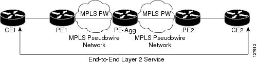
L2VPN Pseudowire Switching allows the user to extend L2VPN pseudowires across an inter-AS boundary or across two separate MPLS networks, as shown in Figure 1 and Figure 2. L2VPN Pseudowire Switching connects two or more contiguous pseudowire segments to form an end-to-end multihop pseudowire. This end-to-end pseudowire functions as a single point-to-point pseudowire.
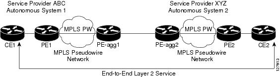
As shown in Figure 2, L2VPN Pseudowire Switching enables you to keep the IP addresses of the edge PE routers private across inter-AS boundaries. You can use the IP address of the autonomous system boundary routers (ASBRs) and treat them as pseudowire aggregation (PE-agg) routers. The ASBRs join the pseudowires of the two domains.
L2VPN Pseudowire Switching also enables you to keep different administrative or provisioning domains to manage the end-to-end service. At the boundaries of these networks, PE-agg routers delineate the management responsibilities.
Figure 1 L2VPN Pseudowire Switching in an Intra-AS Topology
Figure 2 L2VPN Pseudowire Switching in an Inter-AS Topology
How Packets Are Manipulated at the L2VPN Pseudowire Switching Aggregation Point
Switching AToM packets between two AToM pseudowires is the same as switching any MPLS packet. The MPLS switching data path switches AToM packets between two AToM pseudowires. The following list explains exceptions:
•
•
•
•
•
How to Configure L2VPN Pseudowire Switching
Use the following procedure to configure L2VPN Pseudowire Switching on each of the PE-agg routers.
Prerequisites
•
•
Restrictions
In this configuration, you are limited to two neighbor commands after entering the l2 vfi command.
SUMMARY STEPS
1.
2.
3.
4.
5.
6.
7.
8.
9.
DETAILED STEPS
Examples
The following example displays the output of the show mpls l2transport vc command:
Router# show mpls l2transport vcLocal intf Local circuit Dest address VC ID Status------------- -------------------------- --------------- ----- ----MPLS PW 10.0.1.1:100 10.0.1.1 100 UPMPLS PW 10.0.1.1:100 10.0.1.1 100 UPThe following example displays the output of the show vfi command:
Router# show vfiVFI name: test, type: point-to-pointNeighbors connected via pseudowires:Router ID Pseudowire ID10.0.1.1 10010.0.1.1 100Configuration Examples for L2VPN Pseudowire Switching
This section provides the following configuration example:
•
L2VPN Pseudowire Switching in an Inter-AS Configuration: Example
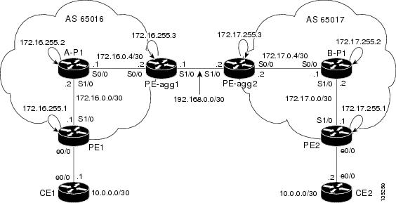
Two separate autonomous systems are able to pass L2VPN packets, because the two PE-agg routers have been configured with L2VPN Pseudowire Switching. This example configuration is shown in Figure 3.
Figure 3 L2VPN Pseudowire Switching in an Inter-Autonomous Sytem
Additional References
The following sections provide references related to L2VPN Pseudowire Switching.
Related Documents
Any Transport over MPLS
Pseudowire redundancy
High availability for AToM
L2VPN interworking
Layer 2 local switching
PWE3 MIB
Pseudowire Emulation Edge-to-Edge MIBs for Ethernet and Frame Relay Services
Packet sequencing
Standards
draft-ietf-pwe3-control-protocol-14.txt
Pseudowire Setup and Maintenance using LDP
draft-martini-pwe3-pw-switching-01.txt
Pseudo Wire Switching
MIBs
RFCs
Technical Assistance
Command Reference
This section documents modified commands only.
•
l2 vfi point-to-point
To establish a point-to-point Layer 2 virtual forwarding interface (VFI) between two separate networks, use the l2 vfi point-to-point command in global configuration mode. To disable the connection, use the no form of this command.
l2 vfi name point-to-point
no l2 vfi name point-to-point
Syntax Description
Command Default
Point-to-point Layer 2 virtual forwarding interfaces are not created.
Command Modes
Global configuration
Command History
Usage Guidelines
If you disable L2VPN Pseudowire Switching with the no l2 vfi point-to-point command, the virtual circuits (VCs) are deleted.
Examples
The following example establishes a point-to-point Layer 2 VFI:
Router(config)# l2 vfi atomvfi point-to-pointRelated Commands
neighbor (L2VPN Pseudowire Switching)
Establishes the two routers with which to form a connection.
neighbor (L2VPN Pseudowire Switching)
To specify the routers that should form a point-to-point Layer 2 virtual forwarding interface (VFI) connection, use the neighbor command in L2 VFI point-to-point configuration mode. To disconnect the routers, use the no form of this command.
neighbor ip-address vc-id {encapsulation mpls |pw-class pw-class-name}
no neighbor ip-address vc-id {encapsulation mpls |pw-class pw-class-name}
Syntax Description
Command Default
Routers do not form a point-to-point Layer 2 VFI connection.
Command Modes
L2 VFI point-to-point configuration
Command History
Usage Guidelines
A maximum of two neighbor commands are allowed when you issue an l2 vfi point-to-point command.
Examples
The following example is a typical configuration of a Layer 2 VFI connection:
Router(config)# l2 vfi atom point-to-point
Router(config-vfi)# neighbor 10.10.10.10 1 encapsulation mpls
Related Commands
l2 vfi point-to-point
Establishes a point-to-point Layer 2 VFI between two separate networks.
show vfi
To display information related to the virtual forwarding instance (VFI), use the show vfi command in privileged EXEC mode.
show vfi vfi-name
Syntax Description
Command Modes
Privileged EXEC
Command History
Examples
This example shows an example of VFI status. The VC ID in the output represents the VPN ID; the VC is identified by the combination of the destination address and the VC ID.
Router# show vfi VPLS-2VFI name: VPLS-2, state: upVPN ID: 100Local attachment circuits:Vlan2Neighbors connected via pseudowires:Peer Address VC ID Split-horizon10.1.1.1 2 Y10.1.1.2 2 Y10.2.2.3 2 NTable 1 explains the fields displayed in the output.
For the VPLS Autodiscovery feature, the command output of the show vfi command includes autodiscovery information.
Router# show vfiLegend: RT= Route-target, S=Split-horizon, Y=Yes, N=NoVFI name: VPLS1, state: up, type: multipointVPN ID: 10, VPLS-ID: 9:10RD: 9:10, RT: 10.10.10.10:150Local attachment circuits:Ethernet0/0.2Neighbors connected via pseudowires:Peer Address VC ID Discovered Router ID S10.7.7.1 10 10.7.7.1 Y10.7.7.2 10 10.1.1.2 Y10.7.7.3 10 10.1.1.3 Y10.7.7.4 10 10.1.1.4 Y10.7.7.5 10 - YVFI name: VPLS2 state: up, type: multipointVPN ID: 11, VPLS-ID: 10.9.9.9:2345RD: 10:11, RT: 10.4.4.4:151Local attachment circuits:Ethernet0/0.3Neighbors connected via pseudowires:Peer Address VC ID Discovered Router ID S10.7.7.1 11 10.7.7.1 Y10.7.7.2 11 10.1.1.5 YTable 2 explains the fields related to VPLS Autodiscovery displayed in the output.
Related Commands
show xconnect
Displays information about xconnect attachment circuits and pseudowires.
CVP, the Cisco Logo, and the Cisco Square Bridge logo are trademarks of Cisco Systems, Inc.; Changing the Way We Work, Live, Play, and Learn is a service mark of Cisco Systems, Inc.; and Access Registrar, Aironet, BPX, Catalyst, CCDA, CCDP, CCIE, CCIP, CCNA, CCNP, CCSP, Cisco, the Cisco Certified Internetwork Expert logo, Cisco IOS, Cisco Press, Cisco Systems, Cisco Systems Capital, the Cisco Systems logo, Cisco Unity, Enterprise/Solver, EtherChannel, EtherFast, EtherSwitch, Fast Step, Follow Me Browsing, FormShare, GigaDrive, GigaStack, HomeLink, Internet Quotient, IOS, iPhone, IP/TV, iQ Expertise, the iQ logo, iQ Net Readiness Scorecard, iQuick Study, LightStream, Linksys, MeetingPlace, MGX, Networking Academy, Network Registrar, Packet, PIX, ProConnect, RateMUX, ScriptShare, SlideCast, SMARTnet, StackWise, The Fastest Way to Increase Your Internet Quotient, and TransPath are registered trademarks of Cisco Systems, Inc. and/or its affiliates in the United States and certain other countries.
All other trademarks mentioned in this document or Website are the property of their respective owners. The use of the word partner does not imply a partnership relationship between Cisco and any other company. (0612R)
Any Internet Protocol (IP) addresses used in this document are not intended to be actual addresses. Any examples, command display output, and figures included in the document are shown for illustrative purposes only. Any use of actual IP addresses in illustrative content is unintentional and coincidental.
© 2005-2007 Cisco Systems, Inc. All rights reserved.