Downloads |
 Feedback Feedback
|
Table Of Contents
MPLS Label Distribution Protocol (LDP)
Related Features and Technologies
Supported Standards, MIBs, and RFCs
Saving Configurations: MPLS/Tag Switching Commands
Label Bindings, Label Spaces, and LDP Identifiers
LDP TCP Connections and Session Establishment
Configuring LDP for Packet Interfaces Example
Configuring LDP for Label-Controlled ATM Interfaces Example
Configuring LDP for Targeted Sessions Example
Transitioning a Network from TDP to LDP
debug mpls ldp peer state-machine
debug mpls ldp session state-machine
debug mpls ldp targeted-neighbors
debug mpls ldp transport connections
debug mpls ldp transport events
mpls ip (global configuration)
mpls ip (interface configuration)
mpls label protocol (global configuration)
mpls label protocol (interface configuration)
mpls ldp advertise-labels old-style
mpls ldp discovery transport-address
mpls ldp neighbor implicit-withdraw
MPLS Label Distribution Protocol (LDP)
Feature History
This document describes the use of the Multiprotocol Label Switching (MPLS) Label Distribution Protocol (LDP), which enables peer label switch routers (LSRs) in an MPLS network to exchange label binding information for supporting hop-by-hop forwarding along normally routed paths. The document includes the following sections:
•
Supported Standards, MIBs, and RFCs
•
•
Feature Overview
The Cisco MPLS LDP, as standardized by the Internet Engineering Task Force (IETF) and as enabled by Cisco IOS software, allows the construction of highly scalable and flexible IP Virtual Private Networks (VPNs) that support multiple levels of services. LDP sessions with those peers for the purpose of exchanging label binding information.
MPLS LDP enables one LSR to inform another LSR of the label bindings it has made. Once a pair of routers communicate the LDP parameters, they establish a label-switched path (LSP). MPLS LDP enables LSRs to distribute labels along normally routed paths to support MPLS forwarding. This method of label distribution is also called hop-by-hop forwarding. With IP forwarding, when a packet arrives at a router the router looks at the destination address in the IP header, performs a route lookup, and forwards the packet to the next hop. With MPLS forwarding, when a packet arrives at a router the router looks at the incoming label, looks up the label in a table, and then forwards the packet to the next hop. MPLS LDP is useful for applications that require hop-by-hop forwarding, such as MPLS VPNs.
LDP provides a standard methodology for hop-by-hop, or dynamic label, distribution in an MPLS network by assigning labels to routes that have been chosen by the underlying Interior Gateway Protocol (IGP) routing protocols. The resulting labeled paths, called label switch paths (LSPs), forward label traffic across an MPLS backbone to particular destinations. These capabilities enable service providers to implement MPLS-based IP VPNs and IP+ATM services across multivendor MPLS networks.
LDP provides the means for LSRs to request, distribute, and release label prefix binding information to peer routers in a network. LDP enables LSRs to discover potential peers and to establish LDP sessions with those peers for the purpose of exchanging label binding information.
From an historical and functional standpoint, LDP is a superset of the Cisco prestandard Tag Distribution Protocol (TDP), which also supports MPLS forwarding along normally routed paths. For those features that LDP and TDP share in common, the pattern of protocol exchanges between network routing platforms is identical. The differences between LDP and TDP for those features supported by both protocols are largely embedded in their respective implementation details, such as the encoding of protocol messages.
This release of LDP, which supports both the LDP and TDP protocols, provides the means for transitioning an existing network from a TDP environment to an LDP environment. Thus, you can run LDP and TDP simultaneously on any router platform. The routing protocol that you select can be configured on a per-interface basis for directly connected neighbors and on a per-session basis for nondirectly connected (targeted) neighbors. In addition, an LSP across an MPLS network can be supported by LDP on some hops and by TDP on other hops.
Benefits
LDP is an IETF standards tracking protocol. The primary benefit of LDP over the prestandard TDP protocol is that the former increases the number of platforms on which MPLS interoperability can be achieved.
Related Features and Technologies
The MPLS Label Distribution Protocol is used in conjunction with the following:
•
•
•
•
•
•
•
Related Documents
For additional information about MPLS functionality running on routers or switches in a network, consult the following documentation:
•
•
•
•
Supported Platforms
LDP is supported on the following platforms:
•
•
•
•
•
•
The MPLS Label Distribution Protocol is also supported on the Cisco MGX 8850 with the Cisco MGX 8850 Route Processor Module (RPM-PR).
Determining Platform Support Through Cisco Feature Navigator
Cisco IOS software is packaged in feature sets that support specific platforms. To get updated information regarding platform support for this feature, access Cisco Feature Navigator. Cisco Feature Navigator dynamically updates the list of supported platforms as new platform support is added for the feature.
Cisco Feature Navigator is a web-based tool that enables you to determine which Cisco IOS software images support a specific set of features and which features are supported in a specific Cisco IOS image. You can search by feature or release. Under the release section, you can compare releases side by side to display both the features unique to each software release and the features in common.
Cisco Feature Navigator is updated regularly when major Cisco IOS software releases and technology releases occur. For the most current information, go to the Cisco Feature Navigator home page at the following URL:
Availability of Cisco IOS Software Images
Platform support for particular Cisco IOS software releases is dependent on the availability of the software images for those platforms. Software images for some platforms may be deferred, delayed, or changed without prior notice. For updated information about platform support and availability of software images for each Cisco IOS software release, refer to the online release notes or, if supported, Cisco Feature Navigator.
Supported Standards, MIBs, and RFCs
Standards
No new or modified standards are supported by this feature.
MIBS
This feature supports the IETF draft document entitled LDP Specification, draft-ietf-mpls-ldp-08.txt.
To obtain lists of supported MIBs by platform and Cisco IOS release, and to download MIB modules, go to the Cisco MIB website on Cisco.com at the following URL:
http://www.cisco.com/public/sw-center/netmgmt/cmtk/mibs.shtml
RFCs
The LDP implementation supporting the MPLS LDP MIB fully complies with the provisions of Section 10 of RFC 2026, which, in effect, states that the implementation of LDP is recommended for network devices that perform MPLS forwarding along normally routed paths, as determined by destination-based routing protocols.
Prerequisites
Label switching on a router requires that Cisco Express Forwarding (CEF) be enabled on that router. Refer to the chapters on CEF in the following documents for configuration information:
•
•
Configuration Tasks
In most situations, the use of LDP is associated with a router or a switch interface. To configure LDP to operate in an MPLS network with such an interface, you must:
•
•
Configuring LDP
To configure use of LDP for an interface or interfaces, use the following commands beginning in user EXEC mode:
Note
Note
Note
Verifying LDP Configuration
To verify LDP configuration for an interface, issue the following commands:
Step 1
Router# show mpls interfacesInterface IP Tunnel OperationalEthernet1/1/1 Yes (tdp) No NoEthernet1/1/2 Yes (tdp) Yes NoEthernet1/1/3 Yes (tdp) Yes YesPOS2/0/0 Yes (tdp) No NoATM0/0.1 Yes (tdp) No No (ATM labels)ATM3/0.1 Yes (ldp) No Yes (ATM labels)ATM0/0.2 Yes (tdp) No YesStep 2
Router# show mpls ldp discoveryLocal LDP Identifier:118.1.1.1:0Discovery Sources:Interfaces:POS2/0 (ldp): xmit/recvLDP Id: 155.0.0.55:0Tunnel1 (ldp): Targeted -> 133.0.0.33Targeted Hellos:118.1.1.1 -> 133.0.0.33 (ldp): active, xmit/recvLDP Id: 133.0.0.33:0118.1.1.1 -> 168.7.0.16 (tdp): passive, xmit/recvTDP Id: 168.7.0.16:0Router#Step 3
Note
Saving Configurations: MPLS/Tag Switching Commands
A number of configuration commands with both MPLS and tag switching forms will be supported during the transition from a tag switching environment to a standards-based MPLS environment. For example, the mpls ip command is equivalent to the tag-switching ip command.
Refer to Table 2 and Table 3 in the "CLI Command Summary" section for a complete list of commands related to LDP that have both MPLS and tag switching forms.
For commands that support both MPLS and tag switching forms, the tag switching form will be written to saved configurations during the transition period from TDP to LDP. Suppose, for example, that you configured an LC-ATM interface on a router by means of the following commands:
Router# configure terminalRouter(config)# interface ATM3/0.1 mplsRouter(config-if)# ip unnumbered Loopback0router(config-if)# mpls ipRouter(config-if)# mpls label protocol ldpIn this example, the interface ATM3/0.1 mpls command and the mpls ip command have tag switching forms. After you enter these commands and save this configuration or display the running configuration with the show running command, the commands saved or displayed would appear as follows:
interface ATM3/0.1 tag-switchingip unnumbered Loopback0tag-switching ipmpls label protocol ldpWriting the tag switching form of commands with both MPLS and tag switching forms to the saved configuration makes it possible for you to use a router software image that supports LDP to:
•
•
For the above example, older software that supports TDP, but not LDP, would be able to interpret all of the interface configuration commands, except for the mpls label protocol command. The older software would generate a warning message about the unrecognized command; nevertheless, the image would bring up the interface configured to run TDP.
Configuration Examples
This section provides the following configuration information:
•
•
•
LDP Configuration Overview
The next three sections describe aspects of MPLS LDP that will help you understand the configuration examples that follow later for packet interfaces, ATM interfaces, and targeted sessions.
Label Bindings, Label Spaces, and LDP Identifiers
An LDP label binding is an association between a destination prefix and a label. The label used in a label binding is allocated from a set of possible labels called a label space.
LDP supports two types of label spaces:
•
•
LDP uses a 6-byte quantity called an LDP Identifier (or LDP ID) to name label spaces. The LDP convention is: a) the first four bytes of the LDP ID identify the LSR that owns the label space; and b) the last two bytes identify the label space within the LSR. For the platform-wide label space, the last two bytes of the LDP ID are always both 0.
The Cisco convention is that the first four bytes of an LDP ID is a platform IP address called the LDP router ID. The last two bytes are called the local label space ID. The display representation for an LDP ID takes the following form:
<LDP router ID> : <local label space ID>
The following are examples of this form:
133.0.0.33:0, 167.3.0.54:3
The LDP router ID is determined as described below. For purposes of this discussion, "S" represents the set of interfaces that are up and have IP addresses, while "I" represents the interface specified by the mpls ldp router-id command, if any.
a.
b.
c.
LDP Discovery
LDP discovery is a mechanism that reduces the amount of per-peer configuration required for LDP by enabling an LSR to discover potential LDP peers.
An LSR engages in discovery by periodically transmitting LDP Hello messages to signal its desire to advertise label bindings. The LSR sends the LDP Hello messages as UDP packets to the well known LDP port (646).
LDP defines two types of discovery:
•
•
The Hello messages carry the LDP ID of the label space that the sending LSR wants to advertise, as well as other information.
When an LSR receives an LDP Hello message from another LSR, it considers that LSR and the specified label space to be "discovered." After two LSRs discover each other in this manner, they attempt to establish an LDP session (as described in the next section).
LDP TCP Connections and Session Establishment
LDP label distribution between two LSRs requires establishment of an LDP session. LSRs that have discovered each other establish an LDP session by:
•
For Cisco platforms, an LSR will use either its LDP router ID or the IP source address of its discovery Hello messages as the IP address for its endpoint of the TCP connection. The address it intends to use is specified to its LSR peer in the Hello messages it sends.
To establish the TCP connection, each LSR must have IP connectivity (that is, a route) to the IP address for the other LSR's endpoint for the connection.
•
Such parameters include the label distribution method (Downstream Unsolicited or Downstream on Demand) and other parameters.
After successfully opening the session TCP connection and agreeing to parameters for the session, LDP label distribution begins.
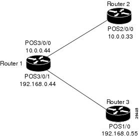
Configuring LDP for Packet Interfaces Example
Figure 1 shows a sample network for configuring the use of LDP for packet interfaces.
Note
The three router configurations that follow accomplish the following:
•
•
•
•
Figure 1 Configuration of LDP for Packet Interfaces
Note
Router 1 Configuration
ip cef distributed !Assumes R1 supports distributed CEFinterface Loopback0 !Loopback interface for LDP ID.ip address 131.25.0.11 255.255.255.255interface POS3/0/0ip address 34.0.0.44 255.0.0.0mpls ip !Enable hop-by-hop MPLS forwardingmpls label protocol ldp !Use LDP for this interfaceinterface POS3/0/1ip address 45.0.0.44 255.0.0.0mpls ip !Enable hop-by-hop MPLS forwarding!Uses TDP (the default)Router 2 Configuration
ip cef distributed !Assumes R2 supports distributed CEFinterface Loopback0 !Loopback interface for LDP ID.ip address 131.25.0.22 255.255.255.255interface POS2/0/0ip address 34.0.0.33 255.0.0.0mpls ip !Enable hop-by-hop MPLS forwardingmpls label protocol ldp !Use LDP for this interfaceRouter 3 Configuration
ip cef !Assumes R3 does not support!distributed CEFinterface Loopback0 !Loopback interface for LDP ID.ip address 131.25.0.33 255.255.255.255interface POS1/0ip address 45.0.0.55 255.0.0.0mpls ip !Enable hop-by-hop MPLS forwarding!Uses TDP (the default)The LDP configuration for Router 1 uses the interface mpls label protocol ldp command because some of its interfaces use LDP and some use TDP. Another way to configure Router 1 is to use the global mpls label protocol ldp command to configure LDP as the default protocol for interfaces and use the interface mpls label protocol tdp command to configure TDP for the POS3/0/1 link to Router 3. This alternative way to configure Router 1 is shown below:
Router 1 Configuration
ip cef distributed !Assumes R1 supports distributed CEFmpls label protocol ldp !Use LDP for the default protocolinterface Loopback0 !Loopback interface for LDP ID.ip address 131.25.0.11 255.255.255.255interface POS3/0/0ip address 34.0.0.44 255.0.0.0mpls ip !Enable hop-by-hop MPLS forwarding!Use LDP (configured i/f default)interface POS3/0/1ip address 45.0.0.44 255.0.0.0mpls ip !Enable hop-by-hop MPLS forwardingmpls label protocol tdp !Use TDP for this interfaceThe configuration of Router 2 also uses the interface mpls label protocol ldp command. If all of its interfaces are to use LDP, then the global mpls label protocol ldp could be used without any interface mpls label protocol commands.
Note
Note
Note
Note
Configuring LDP for Label-Controlled ATM Interfaces Example
The commands required to configure LDP for a LC-ATM interface depend upon the type of interface in use.
There are three different types of LC-ATM interfaces:
•
•
•
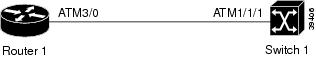
The following example illustrates the configuration of LDP for LC-ATM interfaces of types 1 and 2.
The example is based on the network topology shown in Figure 2, which incorporates a router and an ATM switch connected by means of an ATM link.
Configuring LDP for a router ATM interface is a two-step process:
1.
2.
Configuring LDP for an ATM interface on an ATM switch that is running routing and MPLS control plane software (LC-ATM interface type 2) is similar to configuring LDP for a packet interface.
Figure 2 Configuration of LDP for LC-ATM Interfaces
In the following sample configurations, the use of LDP is configured for the ATM link between Router 1 and Switch 1 (see Figure 2).
Router 1 Configuration:
ip cef distributed !Assumes R1 supports distributed CEFinterface Loopback0ip address 133.0.0.33 255.255.255.255interface ATM3/0.1 mpls !Create the MPLS sub-interfaceip unnumbered Loopback0 !Use IP address of loopback!interface 0 for this interfacempls ip !Enable hop-by-hop MPLS forwardingmpls label protocol ldp !Use LDP for this interfaceSwitch 1 Configuration:
interface Loopback0ip address 121.0.0.21 255.255.255.255interface ATM1/1/1ip unnumbered Loopback0 !Use IP address of loopback!interface 0 for this interfacempls ip !Enable hop-by-hop MPLS forwardingmpls label protocol ldp !Use LDP for this interface
Note
Configuring LDP for Targeted Sessions Example
Some situations require a label distribution session between platforms that are not directly connected. For example, when you issue the mpls ip command on an MPLS traffic engineering tunnel interface, a label distribution session must be established between the tunnel head end and the tail end platforms. Such a session is called a targeted session.
Session establishment for targeted sessions is supported by targeted Hello messages sent between the platforms. Normally the transmission of targeted Hello messages is triggered by some configuration action for the application that requires the targeted session. For example, using the mpls ip command on an MPLS traffic engineering tunnel initiates the transmission of targeted Hello messages from the tunnel head end platform to the tunnel tail end platform.
You can use the mpls ldp neighbor targeted command to improve label convergence time for directly connected neighbor LSRs when the link(s) directly connecting them are down. When the links between the neighbor LSRs are up, both link and targeted Hellos maintain the LDP session. If the links between the neighbor LSRs go down, the targeted Hellos maintain the session allowing the LSRs to retain labels learned from each other. When a link directly connecting the LSRs comes back up, the LSRs can immediately reinstall labels for forwarding use without having to reestablish their LDP session and exchange labels.
Unlike LDP sessions for directly connected peers, targeted sessions are asymmetrical. One peer initiates the session by transmitting targeted Hello messages that carry a "send targeted Hello messages in response" request. This request causes the target peer to respond with targeted Hello messages if its configuration permits it to do so.
The exchange of targeted Hello messages between two nondirectly connected neighbors, N1 and N2, may occur in the following ways:
•
•
The default behavior of an LSR is to ignore requests from other LSRs to send targeted Hello messages. You can configure an LSR to respond to requests for targeted Hello messages by issuing the mpls ldp discovery targeted-hellos accept command.
The protocol used for a targeted session is controlled by the active LSR in the following sense: a passive LSR that is permitted to respond to requests from an active LSR will do so using the protocol of the received targeted Hello messages.
For applications in which targeted sessions are associated with interfaces, you can use the mpls label protocol global and interface configuration commands to specify the protocol for a given interface. For example, the following commands establish an LDP targeted session with the tunnel tail end route:
interface Tunnel1tunnel destination 133.0.0.33mpls ipmpls label protocol ldpTunnel1 is an MPLS traffic engineering tunnel interface.
The output of the show mpls ldp discovery command provides the following information for targeted Hello messages:
•
•
Consider the following output from the show mpls ldp discovery command:
Router# show mpls ldp discoveryLocal LDP Identifier:118.1.1.1:0Discovery Sources:Interfaces:POS2/0 (ldp): xmit/recvLDP Id: 155.0.0.55:0Tunnel1 (ldp): Targeted -> 133.0.0.33Targeted Hellos:118.1.1.1 -> 133.0.0.33 (ldp): active, xmit/recvLDP Id: 133.0.0.33:0118.1.1.1 -> 168.7.0.16 (tdp): passive, xmit/recvTDP Id: 168.7.0.16:0Router#This command output indicates that:
•
•
•
•
•
•
•
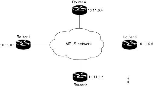
The following examples illustrate the configuration of platforms for targeted sessions using the sample network shown in Figure 3. Note that Routers 1, 4, 5, and 6 in this sample network are not directly connected to each other.
Figure 3 Sample Network for Configuring LDP for Targeted Sessions
The configuration examples presented below accomplish the following:
a.
b.
c.
These examples assume that the active ends of the targeted sessions are associated with tunnel interfaces, such as MPLS traffic engineering tunnels. They show only the commands related to configuring the use of LDP targeted sessions. The examples do not show configuration of the applications that initiate the targeted sessions.
Router 1 Configuration
ip cef distributed !Assumes Router1 supports distributed CEFinterface Loopback0 !Loopback interface for LDP ID.ip address 131.25.0.11 255.255.255.255interface Tunnel14 !Tunnel to Router 4 requiring label distributiontunnel destination 131.11.0.4 !Tunnel endpoint is Router 4mpls label protocol ldp !Use LDP for session with Router 4... !Other configuration for Tunnel14interface Tunnel15 !Tunnel to Router 5 requiring label distributiontunnel destination 131.11.0.5 !Tunnel endpoint is Router 5... !Other configuration for Tunnel15interface Tunnel16 !Tunnel to Router 6 requiring label distributiontunnel destination 131.11.0.6 !Tunnel endpoint is Router 6mpls label protocol ldp !Use LDP for session with Router 6... !Other configuration for Tunnel16For Router 1, the default label protocol for interfaces is TDP because there is no global mpls label protocol ldp command. This requires that the configuration for tunnel interfaces Tunnel14 and Tunnel16 include mpls label protocol ldp commands to specify use of LDP for targeted sessions associated with these interfaces. Since TDP is desired for the targeted session with Router 5, there is no need to include an mpls label protocol tdp command as part of the Tunnel15 configuration because the default protocol for interfaces on Router 1 is TDP.
Router 4 Configuration
ip cef distributed !Assumes Router 4 supports distributed CEFmpls label protocol ldp !Use LDP as default for all interfacesinterface Loopback0 !Loopback interface for LDP ID.ip address 131.25.0.44 255.255.255.255interface Tunnel41 !Tunnel to Router 1 requiring label distributiontunnel destination 131.11.0.1 !Tunnel endpoint is Router 1... !Other configuration for Tunnel41For Router 4, the global mpls label protocol ldp command makes it unnecessary to explicitly specify LDP as part of the configuration for the Tunnel41 targeted session with Router 1.
Router 5 Configuration
ip cef !Assumes Router 5 doesn't support dist. CEFinterface Loopback0 !Loopback interface for LDP ID.ip address 131.25.0.55 255.255.255.255interface Tunnel51 !Tunnel to Router 1 requiring label distributiontunnel destination 131.11.0.1 !Tunnel endpoint is Router 1... !Other configuration for Tunnel51Router 5 must use TDP for all targeted sessions it participates in as an active router because its configuration contains neither the global mpls label protocol ldp command nor the interface mpls label protocol ldp command.
Router 6 Configuration
ip cef distributed !Assumes Router 6 supports distributed CEFinterface Loopback0 !Loopback interface for LDP ID.ip address 131.25.0.66 255.255.255.255mpls ldp discovery targeted-hellos accept from LDP_SOURCES!Respond to requests for targeted hellos!from sources permitted by acl LDP_SOURCESip access-list standard LDP_SOURCES !Define acl for targeted hello sources.permit 131.11.0.1 !Accept targeted hello request from Router 1.deny any !Deny requests from other sources.By default, a router cannot be a passive neighbor in targeted sessions. Therefore, Router 1, Router 4, and Router 5 can only be active neighbors in any targeted sessions they are part of because their configuration does not permit them to be passive. The mpls ldp discovery targeted-hello accept command permits Router 6 to be a passive target in targeted sessions with Router 1. Router 6 can also be an active neighbor in targeted sessions, although the example does not include such a configuration.
Transitioning a Network from TDP to LDP
The software for this release facilitates the orderly transition of a network that uses TDP to one that uses LDP. Key software features supporting this transition to LDP include the following:
•
•
•
•
These software features enable a staged transition from TDP to LDP on a link-by-link or a targeted session-by-session basis.
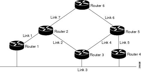
In considering the steps involved in configuring the simple network shown in Figure 4 to use LDP, assume that the following conditions apply:
•
•
•
–
–
Figure 4 Sample Network for Transitioning from TDP to LDP
To accomplish the transition from TDP to LDP for the network topology shown in Figure 4, perform the following steps:
Step 1
Verify proper MPLS operation.
Step 2
The mpls label protocol both command enables Router 1 and Router 3 to use LDP or TDP for label distribution sessions with neighbors directly connected to Link 3 (with a preference for LDP). The resulting configuration establishes:
•
•
•
Verify proper MPLS operation.
Step 3
Verify proper MPLS operation.
Step 4
Verify proper MPLS operation. You can do so in two separate steps, if desired—one for Link 4 and one for Link 5.
Step 5
Verify proper MPLS operation. You can do so in two separate steps, if desired—one for Link 6 and one for Link 7.
Step 6
Verify proper MPLS operation.
Note
Step 7
To do so, add the mpls label protocol ldp command to the configuration of Tunnel15 on Router 1. This assumes that Router 5, which is passive for targeted sessions between Router 1 and Router 5, has previously been configured to accept targeted Hello messages from Router 1 via the mpls ldp discovery targeted-hello accept command.
Verify proper MPLS operation.
Step 8
Verify proper MPLS operation.
This step completes the transition of the network from TDP to LDP.
At this point, you could make the following additional changes to "clean up" each of the configurations:
1.
2.
CLI Command Summary
The CLI commands described in this document fall into three categories:
•
•
•
Command Reference
This section describes the following MPLS debugging, configuration, and display commands:
•
•
•
•
•
•
•
•
•
•
•
•
•
debug mpls atm-ldp api
To display information about the virtual channel identifier (VCI) allocation of label virtual circuits (LVCs), label-free requests, and cross-connect requests, use the debug mpls atm-ldp api command in privileged EXEC mode. To disable this feature, use the no form of this command.
debug mpls atm-ldp api
no debug mpls atm-ldp api
Syntax Description
This command has no arguments or keywords.
Defaults
This command has no default behavior or values.
Command Modes
Privileged EXEC
Command History
Usage Guidelines
Use the debug mpls atm-ldp api command in conjunction with the debug mpls atm-ldp routes and debug mpls atm-ldp states command to display more complete information about an LVC.
Examples
The following shows sample output from the debug mpls atm-ldp api command:
Router# debug mpls atm-ldp apiTailend Router Free label Req 167.50.0.0 on ATM0/0.2 VPI/VCI 1/674TAGATM_API: received label free requestinterface: ATM0/0.2 dir: in vpi: 1 vci: 674TAGATM_API: completed label freeinterface: ATM0/0.2 vpi: 1 vci: 674result: TAGATM_OKTable 4 describes the significant fields shown in the display.
Related Commands
debug mpls atm-ldp failure
To display failure information about the LC-ATM, use the debug mpls atm-ldp failure command in privileged EXEC mode. Use the no form of the command to disable this feature.
debug mpls atm-ldp failure
no debug mpls atm-ldp failure
Syntax Description
This command has no arguments or keywords.
Defaults
This command has no default behavior or values.
Command Modes
Privileged EXEC
Command History
12.2(8)T
This command was introduced.
12.0(21)ST
The command was integrated into Cisco IOS 12.0(21)ST.
12.0(22)S
This command was integrated into Cisco IOS Release 12.0(22)S.
Usage Guidelines
Use the debug mpls atm-ldp failure command to display failure information about the LC-ATM. This command is useful for determining failure cases. This command displays only failure information, unlike the debug mpls atm-ldp api command, which displays all API events.
Examples
This section shows sample output from the debug mpls atm-ldp failure command.
The following failure message displays during a race condition where the LC-ATM attempts to allocate label virtual circuits (LVCs) on an interface where MPLS has been disabled.
Router# debug mpls atm-ldp failureTAGATM_API_FAILURE: allocate_tag_req on ATM1/0/0 tagsw not enabledThe following failure message displays when the LC-ATM fails to deallocate the output leg LVC of a cross connect.
Router# debug mpls atm-ldp failureTAGATM_API_FAILURE: connDeAllocateHalfLeg returned false interface: ATM1/0/0vpi: 1 vci: 48The following failure message displays when a cross connect cannot be installed on the switching fabric. The result code is also provided.Router# debug mpls atm-ldp failureTAGATM_API_FAILURE: setup_xconn_req InstallSvcXconn failed resultThe following message displays when attempts to establish a cross connect fail. The result describes the reason for the failure.
Router# debug mpls atm-ldp failureTCATM-4-XCONNECT_FAILED: 10.254.13.237/32 for ATM0/1/2 ATM1/0/0TAGATM_API: x-conn setup request completedinput interface: ATM0/1/2 vpi: 1 vci: 48output interface: ATM1/0/0 vpi: 2 vci: 2038result = TAGATM_FAILXconnect setup response for 10.254.13.215: failure, 8The following message displays when attempts to remove a cross connect fail. The result describes why the cross connect cannot be removed.
Router# debug mpls atm-ldp failureTCATM-4-XCONNECT_REMOVE_FAILED: Remove XConnect API failed for ATM1/0/12 1/894-> ATM1/0/13 1/528TAGATM_API: x-conn remove request completedinput interface: ATM1/0/12 vpi: 1 vci: 894output interface: ATM1/0/13 vpi: 1 vci: 528result = TAGATM_FAILRelated Commands
debug mpls atm-ldp routes
To display information about the state of the routes for which virtual circuit identifier (VCI) requests are being made, use the debug mpls atm-ldp routes command in privileged EXEC mode. To disable this feature, use the no form of this command.
debug mpls atm-ldp routes
no debug mpls atm-ldp routes
Syntax Description
This command has no arguments or keywords..
Defaults
This command has no default behavior or values.
Command Modes
Privileged EXEC
Command History
Usage Guidelines
When there are many routes and system activities (that is, shutting down interfaces, learning new routes, and so forth), the debug mpls atm-ldp routes command displays extensive information that might interfere with system timing. Most commonly, this interference affects normal label distribution protocol (LDP) operation. To avoid this problem, you can increase the LDP hold time by means of the mpls ldp holdtime command.
Examples
The following shows sample output from the debug mpls atm-ldp routes command:
Router# debug mpls atm-ldp routesCleanupRoutes,not deleting route of idb ATM0/0.2,rdbIndex 0tcatmFindRouteTags,153.7.0.0/16,idb=ATM0/0.2,nh=134.111.102.98,index=0AddNewRoute,153.7.0.0/16,idb=ATM0/0.2CleanupRoutes,153.7.0.0/16CleanupRoutes,not deleting route of idb ATM0/0.2,rdbIndex 0tcatmFindRouteTags,153.8.0.0/16,idb=ATM0/0.2,nh=134.111.102.98,index=0AddNewRoute,153.8.0.0/16,idb=ATM0/0.2CleanupRoutes,153.8.0.0/16CleanupRoutes,not deleting route of idb ATM0/0.2,rdbIndex 0tcatmFindRouteTags,153.9.0.0/16,idb=ATM0/0.2,nh=134.111.102.98,index=0AddNewRoute,153.9.0.0/16,idb=ATM0/0.2CleanupRoutes,153.9.0.0/16CleanupRoutes,not deleting route of idb ATM0/0.2,rdbIndex 0tcatmFindRouteTags,153.10.0.0/16,idb=ATM0/0.2,nh=134.111.102.98,index=0AddNewRoute,153.10.0.0/16,idb=ATM0/0.2CleanupRoutes,153.10.0.0/16CleanupRoutes,not deleting route of idb ATM0/0.2,rdbIndex 0tcatmFindRouteTags,153.11.0.0/16,idb=ATM0/0.2,nh=134.111.102.98,index=0AddNewRoute,153.11.0.0/16,idb=ATM0/0.2CleanupRoutes,153.11.0.0/16Table 5 describes the significant fields in the display.
Related Commands
Changes the time an LDP session is maintained in the absence of LDP messages from the session peer.
debug mpls atm-ldp states
To display information about label virtual circuit (LVC) state transitions as they occur, use the debug mpls atm-ldp states command in privileged EXEC mode. To disable this feature, use the no form of this command.
debug mpls atm-ldp states
no debug mpls atm-ldp states
Syntax Description
This command has no arguments or keywords.
Defaults
This command has no default behavior or values.
Command Modes
Privileged EXEC
Command History
Usage Guidelines
When there are many routes and system activities (such as shutting down interfaces, learning new routes, and so forth), the debug mpls atm-ldp states command outputs extensive information that might interfere with system timing. Most commonly, this interference affects normal label distribution protocol (LDP) operation. To avoid this problem, you should increase the LDP hold time by means of the mpls ldp holdtime command.
Examples
The following shows sample output from the debug mpls atm-ldp states command:
Router# debug mpls atm-ldp statesTransit Output 166.35.0.0 VPI/VCI 1/67 Active -> XmitRelease NoPathTransit Input 166.35.0.0 VPI/VCI 1/466 Active -> ApiWaitParentLoss ParentLossTransit Input 166.35.0.0 VPI/VCI 1/466 ApiWaitParentLoss -> ParentWait ApiSuccessTransit Input 166.35.0.0 VPI/VCI 1/466 ParentWait -> XmitWithdraw NoPathTransit Input 166.35.0.0 VPI/VCI 1/466 XmitWithdraw -> XmitWithdraw TransmitTransit Input 166.35.0.0 VPI/VCI 1/466 XmitWithdraw -> NonExistent ReleaseTransit Input 166.35.0.0 VPI/VCI 1/466 NonExistent -> NonExistent ApiSuccessTable 6 describes the significant fields shown in the display.
Table 6 debug mpls atm-ldp states Field Descriptions
Transit Output
Output side of an LVC.
VPI/VCI
VC value.
Transit Input
Input side of an LVC.
Related Commands
Changes the time an LDP session is maintained in the absence of LDP messages from the session peer.
debug mpls ldp advertisements
To display information about the advertisement of labels and interface addresses to label distribution protocol (LDP) peers, use the debug mpls ldp advertisements command in privileged EXEC mode. To disable this feature, use the no form of this command.
debug mpls ldp advertisements [peer-acl acl] [prefix-acl acl]
no debug mpls ldp advertisements [peer-acl acl] [prefix-acl acl]
Syntax Description
Defaults
Displays information about advertisements to all LDP peers for all prefixes.
Command Modes
Privileged EXEC
Command History
Usage Guidelines
Use this command to monitor the label and address advertisements to LDP peers.
Use the peer-acl or prefix-acl options separately or together to limit the information display to specific LDP peers and/or specific prefixes.
Note
Examples
The following shows sample output from the debug mpls ldp advertisements command:
Router# debug mpls ldp advertisementstagcon: peer 144.0.0.44:0 (pp 0x60E105BC): advertise 130.77.0.33tagcon: peer 144.0.0.44:0 (pp 0x60E105BC): advertise 133.0.0.33tagcon: peer 144.0.0.44:0 (pp 0x60E105BC): advertise 34.0.0.33tagcon: peer 144.0.0.44:0 (pp 0x60E105BC): advertise 103.0.0.33tagcon: peer 144.0.0.44:0 (pp 0x60E105BC): advertise 35.0.0.33tagcon: peer 144.0.0.44:0 (pp 0x60E105BC): advertise 38.0.0.33tagcon: peer 144.0.0.44:0 (pp 0x60E105BC): advertise 34.0.0.0/8, label 3 (#2)tagcon: peer 144.0.0.44:0 (pp 0x60E105BC): advertise 203.0.7.7/32, label 24 (#4)tagcon: peer 144.0.0.44:0 (pp 0x60E105BC): advertise 35.0.0.0/8, label 3 (#8)tagcon: peer 144.0.0.44:0 (pp 0x60E105BC): advertise 103.0.0.0/8, label 3 (#10)tagcon: peer 144.0.0.44:0 (pp 0x60E105BC): advertise 138.1.0.0/16, label 26 (#14)tagcon: peer 144.0.0.44:0 (pp 0x60E105BC): advertise 155.0.0.55/32, label 27 (#16)tagcon: peer 144.0.0.44:0 (pp 0x60E105BC): advertise 38.0.0.0/8, label 3 (#18)tagcon: peer 144.0.0.44:0 (pp 0x60E105BC): advertise 212.10.1.0/24, label 30 (#24)tagcon: peer 144.0.0.44:0 (pp 0x60E105BC): advertise 59.0.0.0/8, label 32 (#28)tagcon: peer 144.0.0.44:0 (pp 0x60E105BC): advertise 144.0.0.44/32, label 33 (#30)tagcon: peer 144.0.0.44:0 (pp 0x60E105BC): advertise 106.0.0.0/8, label 34 (#32)tagcon: peer 144.0.0.44:0 (pp 0x60E105BC): advertise 133.0.0.33/32, label 3 (#34)tagcon: peer 144.0.0.44:0 (pp 0x60E105BC): advertise 45.0.0.0/8, label 39 (#36)Table 7 describes the significant fields shown in the display.
Related Commands
debug mpls ldp backoff
To display information about the label distribution protocol (LDP) backoff mechanism parameters, use the debug mpls ldp backoff command in privileged EXEC mode. To disable this feature, use the no form of this command.
debug mpls ldp backoff
no debug mpls ldp backoff
Syntax Description
This command has no arguments or keywords.
Defaults
This command has no default behavior or values.
Command Modes
Privileged EXEC
Command History
Usage Guidelines
Use this command to monitor backoff parameters configured for LDP sessions.
Examples
The following shows sample output from the debug mpls ldp backoff command:
Router# debug mpls ldp backoffLDP session establishment backoff debugging is onRouter#Jan 6 22:31:13.012: ldp: Backoff peer ok: 12.12.12.12:0; backing off; threshold/count 8/6 Jan 6 22:31:13.824: ldp: Backoff peer ok: 12.12.12.12:1; backing off; threshold/count 8/6 Jan 6 22:31:17.848: ldp: Backoff peer ok: 12.12.12.12:0; backing off; threshold/count 8/6 Jan 6 22:31:18.220: ldp: Backoff peer ok: 12.12.12.12:1; backing off; threshold/count 8/6 Jan 6 22:31:21.908: ldp: Backoff peer ok: 12.12.12.12:0; backing off; threshold/count 8/6 Jan 6 22:31:22.980: ldp: Backoff peer ok: 12.12.12.12:1; backing off; threshold/count 8/6 Jan 6 22:31:25.724: ldp: Backoff peer ok: 12.12.12.12:0; backing off; threshold/count 8/7 Jan 6 22:31:26.944: ldp: Backoff peer ok: 12.12.12.12:1; backing off; threshold/count 8/7 Jan 6 22:31:30.140: ldp: Backoff peer ok: 12.12.12.12:0; backing off; threshold/count 8/7 Jan 6 22:31:31.932: ldp: Backoff peer ok: 12.12.12.12:1; backing off; threshold/count 8/7 Jan 6 22:31:35.028: ldp: Backoff peer ok: 12.12.12.12:0; backing off; threshold/count 8/7 Jan 6 22:31:35.788: ldp: Backoff peer ok: 12.12.12.12:1; backing off; threshold/count 8/7 Jan 6 22:31:39.332: ldp: Update backoff rec: 12.12.12.12:0, threshold = 8, tbl ents 2 Jan 6 22:31:39.640: ldp: Update backoff rec: 12.12.12.12:1, threshold = 8, tbl ents 2Table 8 describes the significant fields shown in the display.
Related Commands
debug mpls ldp bindings
To display information about addresses and label bindings learned from label distribution protocol (LDP) peers by means of LDP downstream unsolicited label distribution, use the debug mpls ldp bindings command in privileged EXEC mode. To disable this feature, use the no form of this command.
debug mpls ldp bindings [peer-acl acl] [prefix-acl acl]
no debug mpls ldp bindings [peer-acl acl] [prefix-acl acl]
Syntax Description
Defaults
Displays information about all bindings learned from all LDP peers.
Command Modes
Privileged EXEC
Command History
Usage Guidelines
Use this command to monitor label bindings and label switch router (LSR) addresses learned from LDP peers.
Note
Examples
The following shows sample output from the debug mpls ldp bindings command:
Router# debug mpls ldp bindingstagcon:tibent(34.0.0.0/8):created; find route tags requesttagcon:tibent(34.0.0.0/8):label 3 (#2) assignedtagcon:tibent(203.0.7.7/32):created; find route tags requesttagcon:tibent(203.0.7.7/32):label 24 (#4) assignedtagcon:tibent(144.0.0.44/32):created; find route tags requesttagcon:tibent(144.0.0.44/32):label 33 (#30) assignedtagcon:tibent(106.0.0.0/8):created; find route tags requesttagcon:tibent(106.0.0.0/8):label 34 (#32) assignedtagcon:tibent(133.0.0.33/32):created; find route tags requesttagcon:tibent(133.0.0.33/32):label 3 (#34) assignedtagcon:tibent(45.0.0.0/8):created; find route tags requesttagcon:tibent(45.0.0.0/8):label 39 (#36) assignedtagcon:Assign peer id; 144.0.0.44:0:id 0tagcon:144.0.0.44:0:144.0.0.44 added to addr<->ldp ident maptagcon:144.0.0.44:0:34.0.0.44 added to addr<->ldp ident maptagcon:144.0.0.44:0:45.0.0.44 added to addr<->ldp ident maptagcon:tibent(144.0.0.44/32):rem label 3 from 144.0.0.44:0 addedtagcon:tibent(34.0.0.0/8):label 3 from 144.0.0.44:0 addedtagcon:tibent(45.0.0.0/8):label 3 from 144.0.0.44:0 addedtagcon:tibent(107.0.0.0/8):created; remote label learnedtagcon:tibent(107.0.0.0/8):label 55 from 144.0.0.44:0 addedtagcon:tibent(203.0.7.7/32):label 209 from 144.0.0.44:0 addedtagcon:tibent(133.0.0.33/32):label 207 from 144.0.0.44:0 addedTable 9 describes the significant fields shown in the display.
Related Commands
debug mpls ldp messages
To display specific information (such as message type, source, and destination) regarding label distribution protocol (LDP) messages sent to and received from LDP peers, use the debug mpls ldp messages command in privileged EXEC mode. To disable this feature, use the no form of this command.
debug mpls ldp messages {sent | received} [all] [peer-acl acl]
no debug mpls ldp messages {sent | received} [all] [peer-acl acl]
Syntax Description
Defaults
All messages sent (for sent keyword) or received (for received keyword) are displayed except for periodic KeepAlive messages.
Command Modes
Privileged EXEC
Command History
Usage Guidelines
LDP requires periodic transmission of KeepAlive messages. If you do not specify the all option, periodic KeepAlive messages are not displayed.
Examples
The following shows sample output from the debug mpls ldp messages received command:
Router# debug mpls ldp messages receivedRouter# debug mpls ldp messages sentldp: Rcvd init msg from 144.0.0.44 (pp 0x0)ldp: Sent init msg to 144.0.0.44:0 (pp 0x0)ldp: Sent keepalive msg to 144.0.0.44:0 (pp 0x0)ldp: Rcvd keepalive msg from 144.0.0.44:0 (pp 0x0)ldp: Sent address msg to 144.0.0.44:0 (pp 0x610F00E0)ldp: Sent label mapping msg to 144.0.0.44:0 (pp 0x610F00E0)ldp: Sent label mapping msg to 144.0.0.44:0 (pp 0x610F00E0)ldp: Sent label mapping msg to 144.0.0.44:0 (pp 0x610F00E0)ldp: Rcvd address msg from 144.0.0.44:0 (pp 0x610F00E0)ldp: Rcvd label mapping msg from 144.0.0.44:0 (pp 0x610F00E0)ldp: Rcvd label mapping msg from 144.0.0.44:0 (pp 0x610F00E0)ldp: Rcvd label mapping msg from 144.0.0.44:0 (pp 0x610F00E0)ldp: Rcvd label mapping msg from 144.0.0.44:0 (pp 0x610F00E0)ldp: Rcvd label mapping msg from 144.0.0.44:0 (pp 0x610F00E0)ldp: Rcvd label mapping msg from 144.0.0.44:0 (pp 0x610F00E0)ldp: Rcvd label mapping msg from 144.0.0.44:0 (pp 0x610F00E0)ldp: Rcvd label mapping msg from 144.0.0.44:0 (pp 0x610F00E0)Table 10 describes the significant fields shown in the display.
Related Commands
debug mpls ldp peer state-machine
To display information about state transitions for label distribution protocol (LDP) sessions, use the debug mpls ldp peer state-machine command in privileged EXEC mode. To disable this feature, use the no form of this command.
debug mpls ldp peer state-machine
no debug mpls ldp peer state-machine
Syntax Description
This command has no arguments or keywords.
Defaults
This command has no default behavior or values.
Command Modes
Privileged EXEC
Command History
Usage Guidelines
LDP manages peer sessions by means of two coupled state machines:
•
•
Use the debug mpls ldp session state-machine command to monitor the lower-level session state machine.
Use the debug mpls ldp peer state-machine command to monitor the higher-level session state machine.
Examples
The following shows sample output from the debug mpls ldp peer state-machine command:
Router# debug mpls ldp peer state-machinetagcon: start session TCP timers for 144.0.0.44:0 (pp 0x610EEC84)tagcon: Enqueue peer up work for 144.0.0.44:0 (pp 0x610EEC84)tagcon: peer 144.0.0.44:0 (pp 0x610EEC84): Event unsol openunsol op pdg -> estabtagcon: Send initial advertisements to peer 144.0.0.44:0tagcon: Initial address advertisement to peer 144.0.0.44:0tagcon: Initial label advertisement to peer 144.0.0.44:0...tagcon: peer 144.0.0.44:0 (pp 0x610EEC84): Event downestab -> destroyedtagcon: peer 144.0.0.44:0 (pp 0x610EEC84): Event cleanup donedestroyed -> non-exTable 11 describes the significant fields shown in the display.
Related Commands
Displays the status of LDP sessions.
Displays information about LDP messages sent to or received from LDP peers.
debug mpls ldp session io
To display the contents of label distribution protocol (LDP) messages sent to and received from LDP peers, use the debug mpls ldp session io command in privileged EXEC mode. To disable this feature, use the no form of this command.
debug mpls ldp session io [all] [peer-acl acl]
no debug mpls ldp session io [all] [peer-acl acl]
Syntax Description
Defaults
Displays the contents of LDP messages sent and received except for periodic KeepAlive messages.
Command Modes
Privileged EXEC
Command History
Usage Guidelines
Displays the contents of all messages sent and received except for periodic KeepAlive messages.
Examples
The following shows sample output from the debug mpls ldp session io command:
Router# debug mpls ldp session io allldp: Rcvd init msg from 144.0.0.44 (pp 0x0)ldp: LDP init msg: PDU hdr: LDP Id: 144.0.0.44:0; Msg Contents:0x00 0x01 0x00 0x20 0x90 0x00 0x00 0x2C 0x00 0x00 0x02 0x00 0x00 0x16 0x00 0x000x10 0x21 0x05 0x00 0x00 0x0E 0x00 0x01 0x00 0xB4 0x00 0x00 0x00 0x00 0x85 0x000x00 0x21 0x00 0x00ldp: Sent init msg to 144.0.0.44:0 (pp 0x0)ldp: LDP init msg: PDU hdr: LDP Id: 133.0.0.33:0; Msg Contents:0x00 0x01 0x00 0x20 0x85 0x00 0x00 0x21 0x00 0x00 0x02 0x00 0x00 0x16 0x00 0x000x06 0x32 0x05 0x00 0x00 0x0E 0x00 0x01 0x00 0xB4 0x00 0x00 0x00 0x00 0x90 0x000x00 0x2C 0x00 0x00ldp: Sent keepalive msg to 144.0.0.44:0 (pp 0x0)ldp: LDP keepalive msg: PDU hdr: LDP Id: 133.0.0.33:0; Msg Contents:0x00 0x01 0x00 0x0E 0x85 0x00 0x00 0x21 0x00 0x00 0x02 0x01 0x00 0x04 0x00 0x000x06 0x33ldp: Rcvd keepalive msg from 144.0.0.44:0 (pp 0x0)ldp: LDP keepalive msg: PDU hdr: LDP Id: 144.0.0.44:0; Msg Contents:0x00 0x01 0x00 0x0E 0x90 0x00 0x00 0x2C 0x00 0x00 0x02 0x01 0x00 0x04 0x00 0x000x10 0x22ldp: Sent address msg to 144.0.0.44:0 (pp 0x610ECDD0)ldp: LDP address msg: PDU hdr: LDP Id: 133.0.0.33:0; Msg Contents:0x00 0x01 0x00 0x34 0x85 0x00 0x00 0x21 0x00 0x00 0x03 0x00 0x00 0x2A 0x00 0x000x06 0x34 0x01 0x01 0x00 0x22 0x00 0x01 0x02 0x00 0x00 0xA3 0x82 0x42 0x00 0x210x82 0x4D 0x00 0x21 0x85 0x00 0x00 0x21 0x22 0x00 0x00 0x21 0x67 0x00 0x00 0x210x23 0x00 0x00 0x21 0x26 0x00 0x00 0x21ldp: Sent label mapping msg to 144.0.0.44:0 (pp 0x610ECDD0)ldp: LDP label mapping msg: PDU hdr: LDP Id: 133.0.0.33:0; Msg Contents:0x00 0x01 0x00 0x22 0x85 0x00 0x00 0x21 0x00 0x00 0x04 0x00 0x00 0x18 0x00 0x000x06 0x36 0x01 0x00 0x00 0x08 0x02 0x00 0x01 0x20 0xCB 0x00 0x07 0x07 0x02 0x000x00 0x04 0x00 0x00 0x00 0x18ldp: Rcvd address msg from 144.0.0.44:0 (pp 0x610ECDD0)ldp: LDP address msg: PDU hdr: LDP Id: 144.0.0.44:0; Msg Contents:0x00 0x01 0x00 0x24 0x90 0x00 0x00 0x2C 0x00 0x00 0x03 0x00 0x00 0x1A 0x00 0x000x10 0x23 0x01 0x01 0x00 0x12 0x00 0x01 0x90 0x00 0x00 0x2C 0x02 0x00 0x00 0xA40x22 0x00 0x00 0x2C 0x2D 0x00 0x00 0x2Cldp: Rcvd label mapping msg from 144.0.0.44:0 (pp 0x610ECDD0)ldp: LDP label mapping msg: PDU hdr: LDP Id: 144.0.0.44:0; Msg Contents:0x00 0x01 0x00 0x22 0x90 0x00 0x00 0x2C 0x00 0x00 0x04 0x00 0x00 0x18 0x00 0x000x10 0x24 0x01 0x00 0x00 0x08 0x02 0x00 0x01 0x20 0x90 0x00 0x00 0x2C 0x02 0x000x00 0x04 0x00 0x00 0x00 0x03Table 12 describes the significant fields shown in the display.
Related Commands
debug mpls ldp session state-machine
To display information about state transitions for label distribution protocol (LDP) sessions, use the debug mpls ldp session state-machine command in privileged EXEC mode. To disable this feature, use the no form of this command.
debug mpls ldp session state-machine [peer-acl acl]
no debug mpls ldp session state-machine [peer-acl acl]
Syntax Description
peer-acl acl
(Optional) Limits the displayed information to that for LDP peers permitted by the access control list (acl).
Defaults
This command has no default behavior or values.
Command Modes
Privileged EXEC
Command History
Usage Guidelines
LDP manages peer sessions by means of two coupled-state machines:
•
•
Use the debug mpls ldp session state-machine command to monitor the lower-level session state machine.
Use the debug mpls ldp peer state-machine command to monitor the higher-level session state machine.
Examples
The following shows sample output from the debug mpls ldp session state-machine command:
Router# debug mpls ldp session state-machineldp: ptcl_adj:144.0.0.44(0x610EED30): Non-existent -> Role pasvldp: create ptcl_adj: tp = 0x610EED30, ipaddr = 144.0.0.44ldp: ptcl_adj:144.0.0.44(0x610EED30): Event: Xport opened;Role pasv -> Role pasvldp: ptcl_adj:34.0.0.44(0x610EED30): Event: Rcv Init;Role pasv -> Init rcvd pasvldp: ptcl_adj:34.0.0.44(0x610EED30): Event: Rcv KA;Init rcvd pasv -> Operldp: ptcl_adj:unknown(0x610EED30): Event: Xport closed;Oper -> Non-existentTable 13 describes the significant fields shown in the display.
Related Commands
debug mpls ldp targeted-neighbors
To display information about the target neighbor mechanism, use the debug mpls ldp targeted-neighbors command in privileged EXEC mode. This mechanism establishes label distribution protocol (LDP) adjacencies to peers that are not directly adjacent, such as peers at either end of a tunnel. To disable this feature, use the no form of this command.
debug mpls ldp targeted-neighbors
no debug mpls ldp targeted-neighbors
Syntax Description
This command has no arguments or keywords.
Defaults
This command has no default behavior or values.
Command Modes
Privileged EXEC
Command History
Usage Guidelines
Platforms that are not directly connected may engage in LDP label distribution (for example, to support two-level labeling across an LSP tunnel).
An LDP session between nondirectly connected label switch routers (LSRs) is called a targeted session and is supported by LDP extended discovery which uses targeted Hello messages sent to specific IP addresses.
An LSR (Router 1) attempting to initiate an LDP targeted session with another LSR (Router 2) sends targeted Hello messages sent to a specific IP address of Router 2. If the configuration of Router 2 permits it to respond to targeted Hello messages from Router 1, it does so, and the LDP session can be established. In this situation, Router 1 is said to be an active LSR for the targeted session because it initiated the targeted Hello messages; Router 2 is said to be a passive LSR for the session because it responded to them.
As with LDP sessions between two directly connected LSRs, it is possible for a targeted session to be the result of multiple discovery activities which are targeted to different IP addresses for the same LSR. In addition, it is possible for both LSRs in a targeted session to be active and for both to be passive.
The debug messages enabled by debug mpls ldp targeted-neighbors report activity relating to targeted sessions.
Examples
The following shows sample output from the debug mpls ldp targeted-neighbors command:
Router# debug mpls ldp targeted-neighborsldp-trgtnbr: 144.0.0.44 Req activeldp-trgtnbr: 144.0.0.44 allocatedldp-trgtnbr: 144.0.0.44 Set peer start; flags 0x0ldp-trgtnbr: 144.0.0.44 Defer peer cleanup; cleancnt 1ldp-trgtnbr: 144.0.0.44 Set peer finished; flags 0xFldp-trgtnbr: 144.0.0.44 ref count incremented to 1ldp-trgtnbr: 144.0.0.44 Release active; ref count decremented to 0ldp-trgtnbr: 144.0.0.44 Clear peer start; flags 0xFldp-trgtnbr: 144.0.0.44 Undefer cleanup start; clearcnt 0, flags 0xCldp-trgtnbr: 144.0.0.44 Undefer cleanup finish; clearcnt 0, flags 0x8ldp-trgtnbr: 144.0.0.44 Clear peer finished; flags 0x8ldp-trgtnbr: 144.0.0.44 freedTable 14 describes the significant fields shown in the display.
Related Commands
debug mpls ldp transport connections
To display information about the Transmission Control Protocol (TCP) connections used to support label distribution protocol (LDP) sessions, use the debug mpls ldp transport connections command in privileged EXEC mode. To disable this feature, use the no form of this command.
debug mpls ldp transport connections [peer-acl acl] [interface interface]
no debug mpls ldp transport connections [peer-acl acl] [interface interface]
Syntax Description
Defaults
Display information about LDP TCP connection activity for all peers and all interfaces.
Command Modes
Privileged EXEC
Command History
Usage Guidelines
Use this command to monitor LDP activity relating to the establishment of the transport (TCP) connection for LDP sessions.
When two devices establish a TCP connection for an LDP session, the device with the larger transport address plays an active role and the other plays a passive role. The active device attempts to establish a TCP connection to the well-known LDP port at the passive device. The passive device waits for the connection to the well-known port to be established.
Examples
The following shows sample output from the debug mpls ldp transport connections command:
Router# debug mpls ldp transport connectionsDebug output at active peer:ldp: Opening listen port 646 for 144.0.0.44, 34.0.0.44ldp: Open LDP listen TCB 0x60E105BC; lport = 646; fhost = 144.0.0.44ldp: Add listen TCB to list; tcb 0x60E105BC; addr 144.0.0.44ldp: Incoming ldp conn 133.0.0.33:646 <-> 144.0.0.44:11042ldp: create ptcl_adj: tp = 0x610ECD64, ipaddr = 144.0.0.44Debug output at passive peer:ldp: Opening ldp conn; adj 0x60BAC33C, 144.0.0.44 <-> 133.0.0.33ldp: ldp conn is up; adj 0x60BAC33C, 144.0.0.44:11042 <-> 133.0.0.33:646Table 15 describes the significant fields shown in the display.
Related Commands
Prints information about the events related to the LDP peer discovery mechanism.
debug mpls ldp transport events
To display information about events related to the label distribution protocol (LDP) peer discovery mechanism, use the debug mpls ldp transport events command in privileged EXEC mode. This mechanism is used to determine the devices with which you wish to establish LDP sessions. To disable this feature, use the no form of this command.
debug mpls ldp transport events [peer-acl acl] [interface]
no debug mpls ldp transport events [peer-acl acl] [interface]
Syntax Description
Defaults
Displays information about LDP discovery activity for all peers and all interfaces.
Command Modes
Privileged EXEC
Command History
Usage Guidelines
Use this command to monitor LDP discovery activity.
This command might generate a great deal of output. Use the peer-acl option or interface option, or both, to limit the output to peers or interfaces of interest.
Note
Examples
The following shows sample output from the debug mpls ldp transport events command:
Router# debug mpls ldp transport eventsldp: enabling ldp on Ethernet1/1/1ldp: Set intf id: intf 0x611D684C, Ethernet1/1/1, not lc-atm, intf_id 0ldp: Set intf id: intf 0x617C5638, ATM0/0.2, not lc-atm, intf_id 0ldp: Send ldp hello; ATM3/0.1, src/dst 8.1.1.1/224.0.0.2, inst_id 1, tcatmldp: Rcvd ldp hello; ATM3/0.1, from 203.0.7.7 (203.0.7.7:2), intf_id 1, opt 0x8, tcatmldp: Send ldp hello; Ethernet1/1/1, src/dst 138.1.0.88/224.0.0.2, inst_id 0ldp: Rcvd ldp hello; Ethernet1/1/1, from 10.105.0.9 (7.1.1.1:0), intf_id 0, opt 0xCldp: ldp Hello from 10.105.0.9 (7.1.1.1:0) to 224.0.0.2, opt 0xCldp: New adj 0x617C5EBC from 10.105.0.9 (7.1.1.1:0), Ethernet1/1/1ldp: Opening ldp conn; adj 0x617C5EBC, 8.1.1.1 <-> 7.1.1.1ldp: ldp conn is up; adj 0x617C5EBC, 8.1.1.1:11013 <-> 7.1.1.1:646ldp: Send ldp hello; ATM3/0.1, src/dst 8.1.1.1/224.0.0.2, inst_id 1, tcatmldp: Rcvd ldp hello; ATM3/0.1, from 203.0.7.7 (203.0.7.7:2), intf_id 1, opt 0x8, tcatmldp: Send ldp hello; Ethernet1/1/1, src/dst 138.1.0.88/224.0.0.2, inst_id 0ldp: Rcvd ldp hello; Ethernet1/1/1, from 10.105.0.9 (7.1.1.1:0), intf_id 0, opt 0xC...ldp: Send ldp hello; Ethernet1/1/1, src/dst 138.1.0.88/224.0.0.2, inst_id 0ldp: Send ldp hello; ATM3/0.1, src/dst 8.1no tag ip.0.2, inst_id 1, tcatmldp: disabling ldp on Ethernet1/1/1ldp: Hold timer expired for adj 0x617C5EBC, will close connldp: Closing ldp conn 8.1.1.1:11013 <-> 7.1.1.1:646, adj 0x617C5EBCldp: Adjacency 0x617C5EBC, 10.105.0.9 timed outldp: Adj 0x617C5EBC; state set to closedldp: Rcvd ldp hello; ATM3/0.1, from 203.0.7.7 (203.0.7.7:2), intf_id 1, opt 0x8, tcatmldp: Ignore Hello from 10.105.0.9, Ethernet1/1/1; no intfTable 16 describes the significant fields shown in the display.
Related Commands
Displays the status of the LDP discovery process.
Displays information about the TCP connections used to support LDP sessions.
mpls ip (global configuration)
To enable MPLS forwarding of IPv4 packets along normally routed paths for the platform, use the mpls ip command in global configuration mode. To disable this feature, use the no form of this command.
mpls ip
no mpls ip
Syntax Description
This command has no arguments or keywords.
Defaults
Label switching of IPv4 packets along normally routed paths is enabled for the platform.
Command Modes
Global configuration
Command History
Usage Guidelines
MPLS forwarding of IPv4 packets along normally routed paths (sometimes called dynamic label switching) is enabled by this command. For a given interface to perform dynamic label switching, this switching function must be enabled for the interface as well as for the platform.
The no form of this command stops dynamic label switching for all platform interfaces regardless of the interface configuration; it also stops distribution of labels for dynamic label switching. However, the no form of this command does not affect the sending of labeled packets through label switch path (LSP) tunnels.
For an LC-ATM interface, the no form of this command prevents the establishment of label virtual circuits (LVCs) originating at, terminating at, or passing through the platform.
Examples
The following example shows that dynamic label switching is disabled for the platform, and all label distribution is terminated for the platform:
Router(config)# no mpls ipRelated Commands
Enables MPLS forwarding of IPv4 packets along normally routed paths for the associated interface.
mpls ip (interface configuration)
To enable MPLS forwarding of IPv4 packets along normally routed paths for a particular interface, use the mpls ip command in interface configuration mode. To disable this feature, use the no form of this command.
mpls ip
no mpls ip
Syntax Description
This command has no arguments or keywords.
Defaults
MPLS forwarding of IPv4 packets along normally routed paths for the interface is disabled.
Command Modes
Interface configuration
Command History
Usage Guidelines
MPLS forwarding of IPv4 packets along normally routed paths is sometimes called dynamic label switching. If dynamic label switching has been enabled for the platform when this command is issued on an interface, label distribution for the interface begins with the periodic transmission of neighbor discovery Hello messages on the interface. When the outgoing label for a destination routed through the interface is known, packets for the destination are labeled with that outgoing label and forwarded through the interface.
The no form of this command causes packets routed out through the interface to be sent unlabeled; this form of the command also terminates label distribution for the interface. However, the no form of the command does not affect the sending of labeled packets through any LSP tunnels that might use the interface.
For an LC-ATM interface, the no form of this command prevents the establishment of label virtual circuits (LVCs) beginning at, terminating at, or passing through the interface.
Examples
The following example shows that label switching is enabled on the specified Ethernet interface:
Router(config)# configure terminalRouter(config-if)# interface e0/2Router(config-if)# mpls ipRelated Commands
mpls label protocol (global configuration)
To specify the default label distribution protocol (LDP) for a platform, use the global mpls label protocol command in global configuration mode. To restore the image default, use the no form of this command.
mpls label protocol { ldp | tdp }
no mpls label protocol
Syntax Description
ldp
Specifies that LDP is the platform default label distribution protocol.
tdp
Specifies that Tag Distribution Protocol (TDP) is the platform default label distribution protocol.
Defaults
If no protocol is explicitly configured by the global mpls label protocol command, TDP is the default label distribution protocol for the platform.
Command Modes
Global configuration
Command History
Usage Guidelines
If neither the global mpls label protocol ldp command nor the interface mpls label protocol ldp command is used, all label distribution sessions will use TDP.
To force all label distribution sessions to use LDP, use the global mpls label protocol ldp command and no interface mpls label protocol commands.
Examples
The following command establishes LDP as the label distribution protocol for the platform:
Router(config)# mpls label protocol ldpRelated Commands
Displays information about one or more or all interfaces that are configured for label switching.
mpls label protocol (interface configuration)
To specify the label distribution protocol to be used on a given interface, use the mpls label protocol command in interface configuration mode. To disable this feature, use the no form of this command.
mpls label protocol {ldp | tdp | both}
no mpls label protocol
Syntax Description
Defaults
If no protocol is explicitly configured for an interface, the default label distribution protocol for the platform is used. To set the platform default protocol, use the global mpls label protocol command.
Command Modes
Interface configuration
Command History
Usage Guidelines
To successfully establish a session for label distribution for a link connecting two label switch routers (LSRs), the link interfaces on the LSRs must be configured to use the same label distribution protocol. If there are multiple links connecting two LSRs, all of the link interfaces connecting the two LSRs must be configured to use the same protocol.
The both option is intended for use with interfaces to multiaccess networks, such as Ethernet and FDDI, where some peers might use LDP and others use TDP. When you specify the both option, the LSR sends both LDP and TDP discovery Hello messages and responds to both types of messages.
Examples
The following command establishes LDP as the label distribution protocol for the interface:
Router(config-if)# mpls label protocol ldpRelated Commands
Displays information about one or more or all interfaces that are configured for label switching.
mpls ldp address-message
To specify advertisement of platform addresses to an LC-ATM label distribution protocol (LDP) peer, use the mpls ldp address-message command in interface configuration mode. To disable this feature, use the no form of this command.
mpls ldp address-message
no mpls ldp address-message
Syntax Description
This command has no arguments or keywords.
Defaults
Do not send LDP Address and Address Withdraw messages to LC-ATM LDP peers.
Command Modes
Interface configuration
Command History
Usage Guidelines
The LDP specification includes Address and Address Withdraw messages used by a label switch router (LSR) to advertise its addresses to its peers.
An LSR uses the addresses it learns from peers when operating in Downstream Unsolicited label advertisement mode to convert between route next hop addresses (found in the LSR routing table) and peer LDP identifiers.
The ability to map between the IP address and the peer LDP identifier is required so that
•
•
In principle, an LSR operating in Downstream On Demand (DoD) mode for an LC-ATM interface does not need this information for two reasons:
•
•
Consequently, Cisco platforms do not normally send Address and Address Withdraw messages to LC-ATM peers.
Some LDP implementations might require the information learned in Address and Address Withdraw messages for LC-ATM. The mpls ldp address-message command is provided to enable interoperability with implementation vendors that require Address messages for LC-ATM.
Note
Examples
The following is an example use of the mpls ldp address-message command:
Router(config-if)# mpls ldp address-messageRelated Commands
Displays information about one or more or all interfaces that are configured for label switching.
mpls ldp advertise-labels
To control the distribution of locally assigned (incoming) labels by means of label distribution protocol (LDP), use the mpls ldp advertise-labels command in global configuration mode. This command is used to control which labels are advertised to which LDP neighbors. To disable this feature, use the no form of this command.
mpls ldp advertise-labels [vrf vpn-name] [interface interface | for prefix-access-list [to peer-access-list]]
no mpls ldp advertise-labels [vrf vpn-name] [interface interface | for prefix-access-list [to peer-access-list]]
Syntax Description
Defaults
The labels of all destinations are advertised to all LDP neighbors.
If the vrf keyword is not specified, this command applies to the default routing domain.
If the interface keyword is not specified, no label is advertised for the interface address.
Command Modes
Global configuration
Command History
Usage Guidelines
To prevent the distribution of any locally assigned labels, use the no mpls ldp advertise-labels command with no optional parameters. To reenable the distribution of all locally assigned labels to all LDP neighbors, use the mpls ldp advertise-labels command with no optional parameters.
You can execute multiple mpls ldp advertise-labels commands. In the aggregate, such commands determine how the LSR advertises local labels. The following rules describe the effects of multiple commands:
1.
2.
a.
b.
3.
a.
b.
c.
d.
e.
Note
Normally, LDP advertises labels only for IP prefixes that are in the routing table. You can use the mpls ldp advertise-labels interface command to force LDP to advertise a label for a prefix constructed from an interface address and a 32-bit mask. Such a prefix is not usually in the routing table.
Examples
In the following example, the router is configured to advertise no locally assigned labels to any LDP neighbors.
Router(config)# no mpls ldp advertise-labelsIn the following example, the router is configured to advertise to all LDP neighbors only the labels for networks 10.101.0.0 and 10.221.0.0.
Router(config)# ip access-list standard pfx-filterRouter(config-std-nacl)# permit 10.101.0.0 0.0.255.255Router(config-std-nacl)# permit 10.221.0.0 0.0.255.255Router(config-std-nacl)# exitRouter(config)# mpls ldp advertise-labels for pfx-filterRouter(config)# no mpls ldp advertise-labelsIn the following example, the router is configured to advertise the label for network 59.0.0.0 only to LSR 155.0.0.55, the label for network 35.0.0.0 only to LSR 133.0.0.33, and the labels for all other prefixes to all LSRs.
Router(config)# ip access-list standard pfx-filter1Router(config-std-nacl)# permit 59.0.0.0Router(config-std-nacl)# exitRouter(config)# ip access-list standard lsr-filter1Router(config-std-nacl)# permit 155.0.0.55Router(config-std-nacl)# exitRouter(config)# ip access-list standard pfx-filter2Router(config-std-nacl)# permit 35.0.0.0Router(config-std-nacl)# exitRouter(config)# ip access-list standard lsr-filter2Router(config-std-nacl)# permit 133.0.0.33Router(config-std-nacl)# exitRouter(config)# mpls ldp advertise-labels for pfx-filter1 to lsr-filter1Router(config)# mpls ldp advertise-labels for pfx-filter2 to lsr-filter2The output of the show mpls ip binding detail command includes the (prefix acl, peer acl) pairs that apply to each prefix. For this example, the applicable pairs are as shown below:
Router# show mpls ip binding detailAdvertisement spec:Prefix acl = pfx-filter1; Peer acl = lsr-filter1Prefix acl = pfx-filter2; Peer acl = lsr-filter235.0.0.0/8, rev 109in label: 16Advertised to:133.0.0.33:0out label: imp-null lsr: 155.0.0.55:0 inuseout label: imp-null lsr: 133.0.0.33:0Advert acl(s): Prefix acl pfx-filter2, Peer acl lsr-filter259.0.0.0/8, rev 108in label: imp-nullAdvertised to:155.0.0.55:0out label: 16 lsr: 155.0.0.55:0out label: 19 lsr: 133.0.0.33:0Advert acl(s): Prefix acl pfx-filter1, Peer acl lsr-filter1113.0.0.33/32, rev 98out label: imp-null lsr: 133.0.0.33:0114.0.0.44/32, rev 99in label: imp-nullAdvertised to:155.0.0.55:0 133.0.0.33:0133.0.0.33/32, rev 101in label: 20Advertised to:155.0.0.55:0 133.0.0.33:0out label: 19 lsr: 155.0.0.55:0out label: imp-null lsr: 133.0.0.33:0 inuse144.0.0.44/32, rev 103in label: imp-nullAdvertised to:155.0.0.55:0 133.0.0.33:0out label: 20 lsr: 155.0.0.55:0out label: 18 lsr: 133.0.0.33:0155.0.0.55/32, rev 104in label: 17Advertised to:155.0.0.55:0 133.0.0.33:0out label: imp-null lsr: 155.0.0.55:0 inuseout label: 17 lsr: 133.0.0.33:0Router#In the following example, the vrf keyword is specified to configure label advertisement in the VPN routing/forwarding instance named vpn1.
Router(config)# mpls ldp advertise-labels vrf vpn1 for pfx-filter1 to lsr-filter1Router(config)# mpls ldp advertise-labels vrf vpn1 for pfx-filter2 to lsr-filter2The following example uses the interface keyword to configure label advertisement for a /32 prefix constructed from the IP address of interface ethernet1/1:
Router(config)# mpls ldp advertise-labels interface ethernet1/1Related Commands
mpls ldp advertise-labels old-style
To cause the interpretation of the for prefix-access-list parameter for mpls ldp advertise-labels commands to be interpreted according to the method used in earlier Cisco IOS software versions, use the mpls ldp advertise-labels old-style command in global configuration mode. To disable this feature, use the no form of this command.
mpls ldp advertise-labels [vrf vpn-name] old-style
no mpls ldp advertise-labels [vrf vpn-name] old-style
Syntax Description
vrf vpn-name
(Optional) Specifies the VPN routing/forwarding instance (vpn-name) for label advertisement.
Defaults
If this command is not specified, the for prefix-access-list parameter in any mpls ldp advertise-labels commands is interpreted according to the rules specified under the "Usage Guidelines" heading for the mpls ldp advertise-labels command.
If the vrf vpn-name parameter is not specified, this command applies to the default routing domain.
Command Modes
Global configuration
Command History
Usage Guidelines
The method for interpreting the for prefix-access-list parameter in mpls ldp advertise-labels commands is defined by Rule 2.a under the "Usage Guidelines" heading described in the mpls ldp advertise-labels command. This Rule 2.a follows normal access list conventions.
However, earlier Cisco IOS software versions used a different method for interpreting the for prefix-access-list parameter in mpls ldp advertise-labels commands. For those earlier software versions, Rule 2.a read as follows:
2. A given prefix can have, at most, one (prefix acl, peer acl) pair that "applies" to it.
a.
This earlier Rule 2.a departed from normal access list conventions in that:
•
•
Use the mpls ldp advertise-labels old-style command to force the use of the old-style method of interpreting the for prefix-access-list parameter used by earlier software versions if the following apply:
•
•
Examples
The following command causes the old-style method of interpreting the for prefix-access-list parameter to be used in executing mpls ldp advertise-labels commands:
Router# mpls ldp advertise-labels old-styleIn the following example, the vrf keyword is specified to configure label advertisement in the VPN routing/forwarding instance named vpn1.
Router(config)# mpls ldp advertise-labels vrf vpn1 old-styleRouter(config)#Related Commands
mpls ldp atm control-mode
To control the mode used for handling label binding requests on LC-ATM interfaces, use the mpls ldp atm control-mode command in global configuration mode. To disable this feature, use the no form of this command.
mpls ldp atm control-mode {ordered | independent}
no mpls ldp atm control-mode {ordered | independent}
Syntax Description
Defaults
The default is ordered control mode.
Command Modes
Global configuration
Command History
Usage Guidelines
Use of ordered control mode by an ATM device acting as a transit LSR in an ATM cloud ensures that the device will receive labeled packets to forward only after it has learned the outgoing labels required by MPLS to forward the packets. Ordered control mode relieves the device of the burden of reassembling cells into packets that must be forwarded by means of the normal (non-MPLS) packet forwarding or discard mechanisms.
Use of independent control mode on ATM transit LSRs might slightly reduce the time an ATM edge router must wait to use an ATM label switched path (LSP) it has initiated. Independent control mode eliminates the need for the edge router to wait for the Label Request/Label Mapping signaling to traverse the ATM cloud from edge router ingress to egress and back before it can send packets into the LSP. However, there is a risk that an ATM transit device might receive labeled packets before it has learned the outgoing labels required for MPLS forwarding, thus forcing the transit device to reassemble the cells into a packet that it is likely to discard.
Examples
In the following example, the mode for handling LDP Label Request messages is set to "independent" for the platform:
Router# mpls ldp atm control-mode independentmpls ldp atm vc-merge
To control whether the vc-merge (multipoint-to-point) capability is supported for unicast label virtual circuits (LVCs), use the mpls ldp atm vc-merge command in global configuration mode. To disable this feature, use the no form of this command.
mpls ldp atm vc-merge
no mpls ldp atm vc-merge
Syntax Description
This command has no arguments or keywords.
Defaults
The ATM-VC merge capability is enabled by default if the hardware supports this feature; otherwise, the feature is disabled.
Command Modes
Global configuration
Command History
Usage Guidelines
Use of VC merge helps conserve ATM labels by allowing incoming LSPs from different sources for the same destination to be merged onto a single outgoing VC.
Examples
In the following example, the ATM-VC merge capability is disabled:
Router# no mpls ldp atm vc-mergeRelated Commands
Displays the ATM MPLS capabilities negotiated with LDP neighbors for LC-ATM interfaces.
mpls ldp backoff
To configure parameters for the label distribution protocol (LDP) backoff mechanism, use the mpls ldp backoff command in global configuration mode. To disable this feature, use the no form of this command.
mpls ldp backoff initial-backoff maximum-backoff
no mpls ldp backoff initial-backoff maximum-backoff
Syntax Description
Defaults
The initial backoff value is 15 seconds and grows to a maximum value of 120 seconds.
Command Modes
Global configuration
Command History
Usage Guidelines
The LDP backoff mechanism prevents two incompatibly configured label switch routers (LSRs) from engaging in an unthrottled sequence of session setup failures. For example, an incompatibility arises when two neighboring routers attempt to perform LC-ATM (label-controlled ATM) but the two are using different ranges of VPI/VCI values for labels.
If a session setup attempt fails due to an incompatibility, each LSR delays its next attempt (that is, backs off), increasing the delay exponentially with each successive failure until the maximum backoff delay is reached.
The default settings correspond to the lowest settings for initial and maximum backoff values defined by the LDP protocol specification. You should change the settings from the default values only if such settings result in undesirable behavior.
Examples
The following command shows how to set the initial backoff delay to 30 seconds and the maximum backoff delay to 240 seconds:
Router(config)# mpls ldp backoff 30 240Related Commands
mpls ldp discovery
To configure the interval between transmission of consecutive label distribution protocol (LDP) Discovery Hello messages, or the hold time for a discovered LDP neighbor, or the neighbors from which requests for targeted Hello messages may be honored, use the mpls ldp discovery command in global configuration mode. To disable this feature, use the no form of this command.
mpls ldp discovery {hello {holdtime | interval} seconds | targeted-hello
{holdtime | interval} seconds | accept [from acl]}no mpls ldp discovery {hello {holdtime | interval} | targeted-hello
{holdtime | interval} | accept [from acl]}Syntax Description
Defaults
The default value for the holdtime keyword is 15 seconds for link Hello messages and 45 seconds for targeted Hello messages.
The default value for the interval keyword is 5 seconds.
Requests for targeted Hello messages are not accepted from any neighbor.
Command Modes
Global configuration
Command History
Usage Guidelines
When the discovery hold time elapses for a neighbor discovered on an interface or for a neighbor discovered by means of a targeted Hello message, the record associating the neighbor with that interface or that targeted Hello message source is discarded. If an LDP session exists with a neighbor, but a discovery record no longer exists for that neighbor, the LDP session is terminated.
Setting the hold time too high causes LDP to be slow in detecting link outages; setting the hold time too low might cause LDP to terminate sessions when a Hello message is dropped during traffic bursts on a link.
The exchange of targeted Hello messages between two nondirectly connected neighbors (N1 and N2) may occur in the following ways:
•
N1's targeted Hello messages carry a request that N2 send targeted Hello messages in response. To respond, N2's configuration must permit it to respond to N1. The mpls ldp discovery targeted-hello accept command is used to configure whether N1 may respond to requests for targeted Hello messages.
•
Both, one, or neither of N1 and N2 may be passive, depending on whether they have been configured to respond to requests for targeted Hello messages from the other.
Note
Examples
In the following example, the period of time for which a neighbor discovered on an interface is remembered if no Hello messages are received is set to 30 seconds:
Router# configure terminalRouter(config)# mpls ldp discovery hello holdtime 30The following example configures the router to respond to requests for targeted Hello messages from neighbors 157.13.0.23 and 168.73.0.18:
Router(config)# ip access standard TRGT_ACCEPTRouter(config-nacl)# permit 157.13.0.23Router(config-nacl)# permit 168.73.0.18Router(config-nacl)# exitRouter(config)# mpls ldp discovery targeted-hello accept from TRGT_ACCEPTRelated Commands
mpls ldp discovery transport-address
To specify the transport address advertised in label distribution protocol (LDP) Discovery Hello messages sent on an interface, use the mpls ldp discovery transport-address command in interface configuration mode. To disable this feature, use the no form of this command.
mpls ldp discovery transport-address {interface | IP address}
no mpls ldp discovery transport-address
Syntax Description
interface
Specifies that the interface IP address should be advertised as the transport address.
IP address
Specifies that the IP address should be advertised as the transport address.
Defaults
The default behavior when this command has not been issued for an interface depends on the interface type.
Unless the interface is a label-controlled ATM (LC-ATM) interface, LDP advertises its LDP Router ID as the transport address in LDP Discovery Hello messages sent from the interface.
If the interface is an LC-ATM interface, no transport address is explicitly advertised in LDP Discovery Hello messages sent from the interface.
Command Modes
Interface configuration
Command History
Usage Guidelines
The establishment of an LDP session between two routers requires a session TCP connection by which label advertisements can be exchanged between the routers. To establish the session TCP connection, each router must know the transport address (IP address) of the other router.
The LDP discovery mechanism provides the means for a router to advertise the transport address for its end of a session TCP connection. The transport address advertisement itself may be explicit, in which case it appears as part of the contents of Discovery Hello messages sent to the peer, or implicit, in which case it does not, and the peer uses the source IP address of received Hello messages for the peer's transport address.
The mpls ldp discovery transport-address command provides the means to modify the default behavior described above. When the interface keyword is specified, LDP advertises the IP address of the interface in LDP Discovery Hello messages sent from the interface. When the IP address argument is specified, LDP advertises the specified IP address in LDP Discovery Hello messages sent from the interface.
Note
Examples
The following example specifies that the LDP transport address for interface pos2/0 should be the interface IP address; it also specifies that the IP address 145.22.0.56 of interface pos3/1 should be the LDP transport address.
Router(config#) interface pos2/0Router(config-if)# mpls ldp discovery transport-address interfaceRouter(config#) interface pos3/1Router(config-if)# mpls ldp discovery transport-address 145.22.0.56Related Commands
Displays the status of the LDP discovery process.
Displays the status of LDP sessions.
mpls ldp explicit-null
To cause a router to advertise an Explicit Null label in situations where it would normally advertise an Implicit Null label, use the mpls ldp explicit-null command in global configuration mode. To disable this feature, use the no form of this command.
mpls ldp explicit-null [for prefix-acl | to peer-acl | for prefix-acl to peer-acl]
no mpls ldp explicit-null
Syntax Description
Defaults
The default behavior is to advertise Implicit Null for directly connected routes unless the command mpls ldp explicit-null has been executed.
Command Modes
Global configuration
Command History
Usage Guidelines
Normally, label distribution protocol (LDP) advertises an Implicit Null label for directly connected routes. The Implicit Null label causes the previous hop (penultimate) router to do penultimate hop popping. Situations exist where it might be desirable to prevent the penultimate router from performing penultimate hop popping and to force it to replace the incoming label with the Explicit Null label.
When you issue the mpls ldp explicit-null command, Explicit Null is advertised in place of Implicit Null for directly connected prefixes permitted by prefix-acl to peers permitted by peer-acl.
If you do not specify the prefix-acl argument in the command, Explicit Null is advertised in place of Implicit Null for all directly connected prefixes.
If you do not specify the peer-acl argument in the command, Explicit Null is advertised in place of Implicit Null to all peers.
Examples
The following command shows how to cause Explicit Null to be advertised for all directly connected routes to all LDP peers:
Router(config)# mpls ldp explicit-nullThe following command sequence shows how to cause Explicit Null to be advertised for directly connected route 137.5.0.0 to all LDP peers and Implicit Null to be advertised for all other directly connected routes:
Router(config)# mpls ldp explicit-nullRouter(config)# ip access-list standard adv-exp-nullRouter(config-std-nacl)# permit 137.5.0.0Router(config-std-nacl)# deny anyRouter(config-std-nacl)#Related Commands
mpls ldp holdtime
To change the time for which an label distribution protocol (LDP) session is maintained in the absence of LDP messages from the session peer, use the mpls ldp holdtime command in global configuration mode. To disable this feature, use the no form of this command.
mpls ldp holdtime seconds
no mpls ldp holdtime seconds
Syntax Description
seconds
Number from 15 to 2147483, that defines the time, in seconds, an LDP session is maintained in the absence of LDP messages from the session peer. The default is 180.
Defaults
The default value for the seconds argument is 180.
Command Modes
Global configuration
Command History
Usage Guidelines
When an LDP session is established between two LSRs, the hold time used for the session is the lower of the values configured on the two LSRs.
Examples
The following example shows how to configure the hold time of LDP sessions for 30 seconds:
Router# mpls ldp holdtime 30Related Commands
Displays current LDP parameter.
Displays specified entries from the ATM label binding database.
mpls ldp loop-detection
To enable the label distribution protocol (LDP) optional loop detection mechanism, use the mpls ldp loop-detection command in global configuration mode. To disable this feature, use the no form of this command.
mpls ldp loop-detection
no mpls ldp loop-detection
Syntax Description
This command has no optional keywords or arguments.
Defaults
LDP loop detection is disabled.
Command Modes
Global configuration
Command History
Usage Guidelines
The LDP loop detection mechanism is intended for use in networks of non-TTL (time-to-live) decrementing devices (for example, ATM switches) that are incapable of fairly allocating device resources among traffic flows.
When configured, the LDP loop detection mechanism is used with the Downstream on Demand method of label distribution, supplementing the Downstream on Demand hop count mechanism to detect looping LSPs that might occur during routing transients. When looping LSPs are detected, the loop is not set up.
Examples
The following command sets the LDP loop detection mechanism on:
Router(config)# mpls ldp loop-detectionRelated Commands
Limits the number of hops permitted in an LSP established by the Downstream on Demand method of label distribution.
mpls ldp maxhops
To limit the number of hops permitted in a label switched path (LSP) established by the Downstream on Demand method of label distribution, use the mpls ldp maxhops command in global configuration mode. To disable this feature, use the no form of this command.
mpls ldp maxhops number
no mpls ldp maxhops
Syntax Description
Defaults
The default is 254 hops.
Command Modes
Global configuration
Command History
Usage Guidelines
When an ATM label switch router (LSR) initiates a request for a label binding, it sets the hop count value in the Label Request message to 1. Subsequent ATM-LSRs along the path to the edge of the ATM label switching region increment the hop count before forwarding the Label Request message to the next hop.
When an ATM LSR receives a Label Request message, it does not send a Label Mapping message in response, nor does it propagate the request to the destination next hop if the hop count value in the request equals or exceeds the maxhops value. Instead, the ATM LSR returns an error message that specifies that the maximum allowable hop count has been reached. This threshold is used to prevent forwarding loops in the setting up of label switch paths across an ATM region.
Examples
The following example shows how to set the hop count limit to 10:
Router(config)# mpls ldp maxhops 10Related Commands
mpls ldp neighbor implicit-withdraw
To configure the advertisement of a new label for a Forwarding Equivalence Class (FEC) without the withdrawal of the previously advertised label, use the mpls ldp neighbor implicit-withdraw command in global configuration mode. To disable this option for the specified neighbor, use the no form of this command.
mpls ldp neighbor [vrf vpn-name] ip-addr implicit-withdraw
no mpls ldp neighbor [vrf vpn-name] ip-addr [implicit-withdraw]
Syntax Description
vrf vpn-name
(Optional) VPN routing/forwarding instance for the specified neighbor.
ip-addr
Router ID (IP address) that identifies a neighbor.
Defaults
When the vrf keyword is not specified in this command, the label distribution protocol (LDP) neighbor is configured in the default routing domain.
If this command is not configured, when it is necessary for LDP to change the label it has advertised to a neighbor for some prefix, it will withdraw the previously advertised label before advertising the new label to the neighbor.
For the no form of the command, if the implicit-withdraw keyword is not specified, all configuration information for the specified neighbor reverts to the defaults and the neighbor record is deleted.
Command Modes
Global configuration
Command History
12.0(21)ST
This command was modified to add the implicit-withdraw keyword.
12.0(22)S
This command was integrated into Cisco IOS Release 12.0(22)S.
Usage Guidelines
By default, in Cisco IOS Release 12.0(21)ST and later, LDP withdraws the previously advertised label using a withdraw message before advertising a new label for a FEC. In Cisco IOS releases prior to 12.0(21)ST, LDP did not withdraw a previously advertised label before advertising a new label for a FEC. In these older releases, the new label advertisement served as an implied withdraw and LDP did not send a withdraw message. To cause LDP to operate as it did in releases before Cisco IOS 12.0(21)ST, that is, LDP will advertise a new label for a FEC without first withdrawing the previously advertised label, use the implicit-withdraw keyword with this command.
Router(config)# mpls ldp neighbor 10.10.10.10 implicit-withdrawUsing the implicit-withdraw keyword avoids the overhead of label withdraw and label release message exchanges.
To disable the implicit-withdraw option, use the no form of the command with the implicit-withdraw keyword. This returns the router to the default, which requires that LDP withdraw the previously advertised label for a FEC before advertising a new label.
Router(config)# no mpls ldp neighbor 10.10.10.10 implicit-withdrawExamples
In the following example, LDP does not send a label-withdraw message to the neighbor whose router ID is 10.10.10.10 when a need exists to change the previously advertised label for a FEC:
Router(config)# mpls ldp neighbor 10.10.10.10 implicit-withdrawRelated Commands
mpls ldp neighbor password
To configure a password key for computing MD5 checksums for the session Transmission Control Protocol (TCP) connection with the specified neighbor, use the mpls ldp neighbor password command in global configuration mode. To disable this option for the specified neighbor, use the no form of this command.
mpls ldp neighbor [vrf vpn-name] ip-addr password [0-7] pswd-string
no mpls ldp neighbor [vrf vpn-name] ip-addr [password [0-7] pswd-string]
Syntax Description
Defaults
Unless the TCP MD5 Signature Option is explicitly configured with the password pswd-string keyword and argument for session TCP connections, the option is not used.
When the vrf keyword is not specified in this command, the label distribution protocol (LDP) neighbor is configured in the default routing domain.
For the no form of the command, if the password keyword is not specified, all configuration information for the specified neighbor reverts to the defaults and the neighbor record is deleted.
Command Modes
Global configuration
Command History
Usage Guidelines
You can invoke authentication between two LDP peers, verifying each segment sent on the TCP connection between the peers. To do so, you must configure authentication on both LDP peers using the same password; otherwise, the peer session is not established.
The authentication capability uses the MD5 (Message Digest 5) algorithm. MD5, an algorithm used in conjunction with SNMP, verifies the integrity of the communication, authenticates the origin of the message, and checks for timeliness.
Invoking the mpls ldp neighbor password command causes the generation and checking of the MD5 digest for every segment sent on the TCP connection.
Configuring a password for an LDP neighbor causes an existing LDP session to be torn down and a new session to be established.
If a router has a password configured for a neighbor, but the neighbor router does not have a password configured, a message such as the following appears on the console while the two routers attempt to establish an LDP session:
%TCP-6-BADAUTH: No MD5 digest from [peer's IP address]:11003 to [local router's
IP address]:179
Similarly, if the two routers have different passwords configured, a message such as the following appears on the console:
%TCP-6-BADAUTH: Invalid MD5 digest from [peer's IP address]:11004 to [local router's
IP address]:179
Examples
In the following example, the string onethirty9 is configured as the password key for use with MD5 for the neighbor whose router ID is 139.27.0.15:
Router(config)# mpls ldp neighbor 139.27.0.15 password onethirty9In the following example, the string cisco is configured as the password for use with MD5 for the LDP neighbor having router ID 4.4.4.4 in the VPN routing/forwarding instance named vpn1:
Router(config)# mpls ldp neighbor vrf vpn1 4.4.4.4 password ciscoRelated Commands
mpls ldp neighbor targeted
To set up a targeted session with the specified neighbor, use the mpls ldp neighbor targeted command in global configuration mode. To disable this option for the specified neighbor, use the no form of this command.
mpls ldp neighbor [vrf vpn-name] ip-addr targeted [ldp | tdp]
no mpls ldp neighbor [vrf vpn-name] ip-addr [targeted [ldp | tdp]]
Syntax Description
Defaults
When the targeted keyword is not specified, a targeted session is not set up with the neighbor.
For the no form of the command if the targeted keyword is not specified all configuration information for the specified neighbor reverts to the defaults and the neighbor record is deleted.
Command Modes
Global configuration
Command History
Usage Guidelines
If you do not specify the label protocol for the targeted session, the label protocol specified with the mpls label protocol command is used. If the mpls label protocol command is not configured, then TDP is used for the targeted session.
Use the mpls ldp neighbor targeted command when you need to set up a targeted session and other means of establishing targeted sessions do not apply, such as configuring mpls ip on a traffic engineering (TE) tunnel or configuring Any Transport over MPLS (AToM) virtual circuits (VCs). For example, you would use this command to set up a targeted session between directly connected MPLS LSRs when MPLS label forwarding convergence time is an issue.
The mpls ldp neighbor targeted command can improve label convergence time for directly connected neighbor LSRs when the link(s) directly connecting them are down. When the links between the neighbor LSRs are up, both the link and targeted Hellos maintain the LDP session. If the links between the neighbor LSRs go down, the targeted Hellos maintain the session, allowing the label switch routers (LSRs) to retain labels learned from each other. When a link directly connecting the LSRs comes back up, the LSRs can immediately reinstall labels for forwarding use without having to reestablish their LDP session and exchange labels.
Examples
In the following example, the router sets up a targeted session with the neighbor 10.10.10.10 using TDP as the label protocol:
Router(config)# mpls ldp neighbor 10.10.10.10 targetedIn the following example, the router sets up a targeted session with the neighbor 10.10.10.10 using LDP as the label protocol:
Router(config)# mpls label protocol ldpRouter(config)# mpls ldp neighbor 10.10.10.10 targetedAnother way to set up a targeted session using LDP without changing the default label protocol is as follows:
Router(config)# mpls ldp neighbor 10.10.10.10 targeted ldpRelated Commands
mpls ldp router-id
To specify a preferred interface for determining the label distribution protocol (LDP) router ID, use the mpls ldp router-id command in global configuration mode. To disable this feature, use the no form of this command.
mpls ldp router-id interface [force]
no mpls ldp router-id
Syntax Description
Defaults
If the mpls ldp router-id command is not executed, the LDP router ID is determined as follows:
a.
b.
c.
Command Modes
Global configuration
Command History
Usage Guidelines
The normal (default) method for determining the LDP router ID may result in a router ID that is not usable in certain situations. For example, an IP address selected as the LDP router ID might not be advertisable by the routing protocol to a neighboring router. The mpls ldp router-id command provides a means for specifying an interface whose IP address is to be used as the LDP router ID. The specified interface must be operational in order for its IP address to be used as the LDP router ID.
When executed without the force argument, the mpls ldp router-id command modifies the method for determining the LDP router ID by causing selection of the IP address of the specified interface (provided that the interface is operational) the next time it is necessary to select an LDP router ID. The effect of the command is delayed until the next time it is necessary to select an LDP router ID, which is typically the next time the interface whose address is the current LDP router ID is shut down or the address itself is deconfigured.
When executed with the force argument, the effect of the mpls ldp router-id command depends on the current state of the specified interface:
a.
b.
Examples
The following example shows that the pos2/0/0 interface has been specified as the preferred interface for use in determining the LDP router ID. The IP address of such a specified interface is used as the LDP router ID.
Router(config)# mpls ldp router-id pos2/0/0Related Commands
show mpls atm-ldp bindings
To display specified entries from the ATM label binding database, use the show mpls atm-ldp bindings command in privileged EXEC mode. The ATM label binding database contains entries for label VCs on LC-ATM interfaces.
show mpls atm-ldp bindings [network {mask | length}] [local-label vpi vci] [remote-label vpi vci] [neighbor interface]
Syntax Description
Defaults
The entire ATM label binding database is displayed if no optional arguments or keywords are specified.
Note
Command Modes
Privileged EXEC
Command History
Usage Guidelines
Command output can show a summary of entries from the entire database, or the output can be limited to a subset of entries based on the following:
•
•
•
Note
Note
Examples
The following shows sample output from the show mpls atm-ldp bindings command:
Router# show mpls atm-ldp bindingsDestination: 10.24.0.0/24Tailend Router ATM1/0.1 1/39 Active, VCD=3Destination: 10.15.0.15/32Tailend Router ATM1/0.1 1/33 Active, VCD=4Destination: 203.0.7.7/32Headend Router ATM1/0.1 (2 hops) 1/34 Active, VCD=810The following is sample output from the show mpls atm-ldp bindings command on an ATM switch:
Router# show mpls atm-ldp bindingsDestination: 150.0.0.0/16Tailend Switch ATM0/0/3 1/35 Active -> Terminating ActiveDestination: 4.4.4.4/32Transit ATM0/0/3 1/33 Active -> ATM0/1/1 1/33 ActiveTable 17 describes the significant fields shown in the display.
show mpls atm-ldp bindwait
To display the number of bindings waiting for label assignments from a remote MPLS ATM switch, use the show mpls atm-ldp bindwait command in privileged EXEC mode.
show mpls atm-ldp bindwait
Syntax Description
This command has no arguments or keywords.
Defaults
This command has no default behavior or values.
Command Modes
Privileged EXEC
Command History
Usage Guidelines
Use this command to display information about virtual circuits (VCs) in the bindwait state.
Examples
The following shows sample output from the show mpls atm-ldp bindwait command:
Router# show mpls atm-ldp bindwaitWaiting for bind on ATM1/0.23.3.3.1/32 3.3.3.1/32 3.3.3.2/323.3.3.2/32 3.3.3.3/32 3.3.3.3/323.3.3.4/32 3.3.3.4/32 3.3.3.5/323.3.3.5/32 3.3.3.6/32 3.3.3.6/323.3.3.7/32 3.3.3.7/32 3.3.3.8/323.3.3.8/32 3.3.3.9/32 3.3.3.9/32 ...endIf everything is working properly, this command does not display any output.
Related Commands
show mpls atm-ldp capability
To display the MPLS ATM capabilities negotiated with label distribution protocol (LDP) neighbors for LC-ATM interfaces, use the show mpls atm-ldp capability command in privileged EXEC mode.
show mpls atm-ldp capability
Syntax Description
This command has no arguments or keywords.
Defaults
This command always displays all the MPLS ATM capabilities negotiated with all the LDP neighbors.
Command Modes
Privileged EXEC
Command History
Usage Guidelines
When two label switch routers (LSRs) establish an LDP session, they negotiate parameters for the session, such as the range of virtual path identifiers (VPIs) and virtual channel identifiers (VCIs) that will be used as labels.
This command displays the MPLS ATM capabilities negotiated by LDP or the Tag Distribution Protocol (TDP).
Examples
The following shows sample output from the show mpls atm-ldp capability command:
Router# show mpls atm-ldp capabilityVPI VCI Alloc Odd/Even VC MergeATM0/1/0 Range Range Scheme Scheme IN OUTNegotiated [100 - 101] [33 - 1023] UNIDIR - -Local [100 - 101] [33 - 16383] UNIDIR EN ENPeer [100 - 101] [33 - 1023] UNIDIR - -VPI VCI Alloc Odd/Even VC MergeATM0/1/1 Range Range Scheme Scheme IN OUTNegotiated [201 - 202] [33 - 1023] BIDIR - -Local [201 - 202] [33 - 16383] UNIDIR ODD NO NOPeer [201 - 202] [33 - 1023] BIDIR EVEN - -Table 18 describes the significant fields shown in the display.
Related Commands
Controls whether the vc-merge (multipoint-to-point) is supported for unicast label VCs.
show mpls atm-ldp summary
To display summary information about all the entries in the ATM label binding database, use the show mpls atm-ldp summary command in privileged EXEC mode.
show mpls atm-ldp summary
Syntax Description
This command has no arguments or keywords.
Defaults
This command has no default behavior or values.
Command Modes
Privileged EXEC
Command History
Usage Guidelines
Use this command to display dynamic ATM accounting information.
Examples
The following shows sample output from the show mpls atm-ldp summary command:
Router# show mpls atm-ldp summaryTotal number of destinations: 406ATM label bindings summaryinterface total active local remote Bwait Rwait IFwaitATM0/0/0 406 406 404 2 0 0 0ATM0/0/1 406 406 3 403 0 0 0Table 19 describes the significant fields shown in the display.
Related Commands
show isis database verbose
Displays the requested entries from the ATM LDP label binding database.
show mpls interfaces
To display information about one or more or all interfaces that are configured for label switching, use the show mpls interfaces command in privileged EXEC mode.
show mpls interfaces [vrf vpn-name] [interface] [detail]
show mpls interfaces [all]
Syntax Description
Defaults
If no optional keyword or argument is specified in this command, summary information is displayed for each interface that has been configured for label switching in the default routing domain.
Command Modes
Privileged EXEC
Command History
Usage Guidelines
This command shows MPLS information about the specified interface, or about all the interfaces for which MPLS has been configured.
Examples
The following shows sample output generated by the show mpls interfaces command:
Router# show mpls interfacesInterface IP Tunnel OperationalEthernet1/1/1 Yes (tdp) No NoEthernet1/1/2 Yes (tdp) Yes NoEthernet1/1/3 Yes (tdp) Yes YesPOS2/0/0 Yes (tdp) No NoATM0/0.1 Yes (tdp) No No (ATM labels)ATM3/0.1 Yes (ldp) No Yes (ATM labels)ATM0/0.2 Yes (tdp) No Yes
Note
Table 20 describes the significant fields shown in the display.
The following is sample output from the show mpls interfaces command when you specify the detail keyword:
Router# show mpls interfaces detailInterface Ethernet1/1/1:IP labeling enabled (tdp)LSP Tunnel labeling not enabledMPLS operationalMPLS turbo vectorMTU = 1500Interface POS2/0/0:IP labeling enabled (ldp)LSP Tunnel labeling not enabledMPLS not operationalMPLS turbo vectorMTU = 4470Interface ATM3/0.1:IP labeling enabled (ldp)LSP Tunnel labeling not enabledMPLS operationalMPLS turbo vectorMTU = 4470ATM labels: Label VPI = 1Label VCI range = 33 - 65535Control VC = 0/32The following is sample output from the show mpls interfaces command when you specify the all keyword:
Router# show mpls interfaces allInterface IP Tunnel OperationalATM1/1/0.1 Yes (tdp) No YesVRF vpn1:ATM3/0/0.1 Yes (ldp) No YesVRF vpn2:ATM3/0/0.2 Yes (ldp) No YesVRF vpn3:ATM3/0/0.3 Yes (ldp) No YesVRF vpn4:ATM3/0/0.4 Yes (ldp) No YesVRF vpn5:ATM3/0/0.5 Yes (ldp) No YesVRF vpn6:Interface IP Tunnel OperationalATM3/0/0.6 Yes (ldp) No YesVRF vpn7:ATM3/0/0.7 Yes (ldp) No YesVRF vpn8:ATM3/0/0.8 Yes (ldp) No YesVRF vpn9:ATM3/0/0.9 Yes (ldp) No YesVRF vpn10:ATM3/0/0.10 Yes (ldp) No YesVRF vpn11:ATM3/0/0.11 Yes (ldp) No YesVRF vpn12:ATM3/0/0.12 Yes (ldp) No Yes...Related Commands
show mpls ip binding
To display specified information about label bindings learned by the label distribution protocol (LDP), use the show mpls ip binding command in user EXEC or privileged EXEC mode. To summarize information about label bindings learned by LDP, use the show mpls ip binding summary command in privileged EXEC mode.
show mpls ip binding [vrf vpn-name] [network {mask | length} [longer-prefixes]]
[local-label {atm vpi vci | label [- label]}]
[remote-label {atm vpi vci | label [- label]}]
[neighbor address] [local]
[interface interface] [generic | atm]show mpls ip binding summary
Syntax Description
Defaults
All label bindings are displayed when no optional arguments or keywords are specified.
Command Modes
User EXEC
Privileged EXECCommand History
Usage Guidelines
The show mpls ip binding command displays label bindings learned by LDP or the Tag Distribution Protocol (TDP).
A request can specify that the entire database be displayed, that a summary of entries from the database be displayed, or that the display be limited to a subset of entries. The subset can be limited according to any of the following:
•
•
•
•
•
•
Examples
The following shows sample output from the show mpls ip binding command. The output shows all the label bindings in the database.
Router# show mpls ip binding34.0.0.0/8in label: 20out label: 26 lsr: 155.0.0.55:0out vc label: 1/80 lsr: 203.0.7.7:2 ATM1/0.8Active ingress 3 hops (vcd 49)45.0.0.0/8in label: 25in vc label: 1/36 lsr: 203.0.7.7:2 ATM1/0.8Active egress (vcd 55)out label: imp-null lsr: 155.0.0.55:0 inuse66.66.0.66/32in label: 26in vc label: 1/39 lsr: 203.0.7.7:2 ATM1/0.8Active egress (vcd 58)out label: 16 lsr: 155.0.0.55:0 inuse133.0.0.33/32in label: 23out label: 22 lsr: 155.0.0.55:0out vc label: 1/83 lsr: 203.0.7.7:2 ATM1/0.8Active ingress 3 hops (vcd 52)144.0.0.44/32in label: 61out label: 27 lsr: 155.0.0.55:0 inuse150.88.0.0/16in label: 28in vc label: 1/40 lsr: 203.0.7.7:2 ATM1/0.8Active egress (vcd 59)out label: imp-null lsr: 155.0.0.55:0 inuse166.47.0.0/16in label: 33in vc label: 1/46 lsr: 203.0.7.7:2 ATM1/0.8Active egress (vcd 65)out label: imp-null lsr: 155.0.0.55:0 inuse194.44.44.0/24in label: 24in vc label: 1/37 lsr: 203.0.7.7:2 ATM1/0.8Active egress (vcd 56)out label: imp-null lsr: 155.0.0.55:0 inuseRouter#In the following example, a request is made for the display of the label binding information for prefix 194.44.44.0/24:
Router# show mpls ip binding 194.44.44.0 24194.44.44.0/24in label: 24in vc label: 1/37 lsr: 203.0.7.7:2 ATM1/0.8Active egress (vcd 56)out label: imp-null lsr: 155.0.0.55:0 inuseRouter#In the following example, the local-label keyword is used to request that label binding information be displayed for the prefix(es) with local label 58:
Router# show mpls ip binding local-label 58166.253.0.0/16in label: 58out label: imp-null lsr: 155.0.0.55:0 inuseRouter#The following example shows the label bindings for the VPN routing/forwarding instance named vpn1:
Router# show mpls ip binding vrf vpn13.3.0.0/16in label: 117out label: imp-null lsr:14.14.14.14:013.13.13.13/32in label: 1372out label: 268 lsr:14.14.14.14:014.14.14.14/32in label: 118out label: imp-null lsr:14.14.14.14:015.15.15.15/32in label: 1370out label: 266 lsr:14.14.14.14:016.16.16.16/32in label: 8370out label: 319 lsr:14.14.14.14:018.18.18.18/32in label: 21817out label: 571 lsr:14.14.14.14:030.2.0.0/16in label: 6943out label: 267 lsr:14.14.14.14:030.3.0.0/16in label: 2383out label: imp-null lsr:14.14.14.14:030.4.0.0/16in label: 77out label: imp-null lsr:14.14.14.14:030.5.0.0/16in label: 20715out label: 504 lsr:14.14.14.14:030.7.0.0/16in label: 17out label: imp-null lsr:14.14.14.14:030.10.0.0/16in label: 5016out label: 269 lsr:14.14.14.14:030.13.0.0/16in label: 76out label: imp-null lsr:14.14.14.14:0Table 21 describes the significant fields shown in the display.
The following example shows summary information about the label bindings learned by LDP:
Router# show mpls ip binding summaryTotal number of prefixes: 53Generic label bindingsassigned learnedprefixes in labels out labels53 53 51ATM label bindings summaryinterface total active local remote Bwait Rwait IFwaitATM1/0.8 47 47 40 7 0 0 0Router#Table 22 describes the significant fields shown in the display.
Related Commands
Displays specified entries from the ATM label binding database.
Displays the contents of the LIB.
show mpls ldp backoff
To display information about the configured session setup backoff parameters and any potential label distribution protocol (LDP) peers with which session setup attempts are being throttled, use the show mpls ldp backoff command in user EXEC or privileged EXEC mode.
show mpls ldp backoff
Syntax Description
This command has no arguments or keywords.
Defaults
This command has no default behavior or values.
Command Modes
User EXEC
Privileged EXECCommand History
Examples
The following shows sample output from the show mpls ldp backoff command:
Router# show mpls ldp backoffLDP initial/maximum backoff: 30/240 secBackoff table: 2 entriesLDP Id Backoff(sec) Waiting(sec)144.0.0.44:0 60 30155.0.0.55:0 120 90Table 23 describes the significant fields shown in the display.
Related Commands
show mpls ldp bindings
To display the contents of the label information base (LIB), use the show mpls ldp bindings command in user EXEC or privileged EXEC mode:
show mpls ldp bindings [vrf vpn-name] [network {mask | length} [longer-prefixes]]
[local-label label [- label]] [remote-label label [- label]] [neighbor address] [local]Syntax Description
Defaults
If no optional keywords or arguments are supplied, the command displays the LIB for the default routing domain only.
Command Modes
User EXEC
Privileged EXECCommand History
Usage Guidelines
The show mpls ldp bindings command displays label bindings learned by the label distribution protocol (LDP) or Tag Distribution Protocol (TDP).
A request can specify that the entire database be displayed, or that the display be limited to a subset of entries according to the following:
•
•
•
Note
Examples
The following shows sample output from the show mpls ldp bindings command. This form of the command displays the contents of the LIB for the default routing domain.
Router# show mpls ldp bindings34.0.0.0/8, rev 9local binding: label: imp-nullremote binding: lsr: 155.0.0.55:0, label: 17remote binding: lsr: 66.66.0.66:0, label: 18remote binding: lsr: 144.0.0.44:0, label: imp-null45.0.0.0/8, rev 17local binding: label: 19remote binding: lsr: 155.0.0.55:0, label: imp-nullremote binding: lsr: 66.66.0.66:0, label: 16remote binding: lsr: 144.0.0.44:0, label: imp-null66.66.0.66/32, rev 19local binding: label: 20remote binding: lsr: 155.0.0.55:0, label: 19remote binding: lsr: 66.66.0.66:0, label: imp-nullremote binding: lsr: 144.0.0.44:0, label: 18103.0.0.0/8, rev 11local binding: label: imp-null130.77.0.0/16, rev 23local binding: label: 22remote binding: lsr: 155.0.0.55:0, label: 22remote binding: lsr: 144.0.0.44:0, label: 21remote binding: lsr: 66.66.0.66:0, label: 20140.66.0.0/16, rev 96remote binding: lsr: 66.66.0.66:0, label: imp-null155.0.0.55/32, rev 29local binding: label: 25remote binding: lsr: 155.0.0.55:0, label: imp-nullremote binding: lsr: 144.0.0.44:0, label: 24remote binding: lsr: 66.66.0.66:0, label: 24166.45.0.0/16, rev 33local binding: label: 27remote binding: lsr: 155.0.0.55:0, label: imp-nullremote binding: lsr: 66.66.0.66:0, label: 26remote binding: lsr: 144.0.0.44:0, label: 26166.46.0.0/16, rev 35local binding: label: 28remote binding: lsr: 155.0.0.55:0, label: imp-nullremote binding: lsr: 66.66.0.66:0, label: 27remote binding: lsr: 144.0.0.44:0, label: 27...The following is sample output from the show mpls ldp bindings network length longer-prefixes neighbor address variant of the command; it displays labels learned from label switch router (LSR) 144.0.0.44 for network 166.0.0.0 and any of its subnets. The use of the neighbor keyword suppresses the output of local labels and labels learned from other neighbors.
Router# show mpls ldp bindings 166.0.0.0 8 longer-prefixes neighbor 144.0.0.44166.44.0.0/16, rev 31remote binding: lsr: 144.0.0.44:0, label: 25166.45.0.0/16, rev 33remote binding: lsr: 144.0.0.44:0, label: 26166.245.0.0/16, rev 71remote binding: lsr: 144.0.0.44:0, label: 45166.246.0.0/16, rev 73remote binding: lsr: 144.0.0.44:0, label: 46...The following shows sample output from the show mpls ldp bindings vrf vpn1 command, which displays the label bindings for the specified VPN routing/forwarding instance named vpn1.
Router# show mpls ldp bindings vrf vpn13.3.0.0/16, rev 164local binding: label:117remote binding:lsr:14.14.14.14:0, label:imp-null13.13.13.13/32, rev 1650local binding: label:1372remote binding:lsr:14.14.14.14:0, label:26814.14.14.14/32, rev 165local binding: label:118remote binding:lsr:14.14.14.14:0, label:imp-null15.15.15.15/32, rev 1683local binding: label:1370remote binding:lsr:14.14.14.14:0, label:26616.16.16.16/32, rev 775local binding: label:8370remote binding:lsr:14.14.14.14:0, label:31918.18.18.18/32, rev 1655local binding: label:21817remote binding:lsr:14.14.14.14:0, label:57130.2.0.0/16, rev 1653local binding: label:6943remote binding:lsr:14.14.14.14:0, label:26730.3.0.0/16, rev 413local binding: label:2383remote binding:lsr:14.14.14.14:0, label:imp-null30.4.0.0/16, rev 166local binding: label:77remote binding:lsr:14.14.14.14:0, label:imp-null30.5.0.0/16, rev 1429local binding: label:20715remote binding:lsr:14.14.14.14:0, label:50430.7.0.0/16, rev 4local binding: label:17remote binding:lsr:14.14.14.14:0, label:imp-null30.10.0.0/16, rev 422local binding: label:5016remote binding:lsr:14.14.14.14:0, label:269...Table 24 describes the significant fields shown in the display.
Related Commands
show mpls ldp discovery
To display the status of the label distribution protocol (LDP) discovery process, use the show mpls ldp discovery command in user EXEC or privileged EXEC mode. This command generates a list of interfaces over which the LDP discovery process is running.
show mpls ldp discovery [vrf vpn-name]
show mpls ldp discovery [all]
Syntax Description
Defaults
This command displays neighbor discovery information for the default routing domain if an optional argument is not specified.
Command Modes
User EXEC
Privileged EXECCommand History
Usage Guidelines
This command displays neighbor discovery information for LDP or Tag Distribution Protocol (TDP).
Examples
The following shows sample output from the show mpls ldp discovery command:
Router# show mpls ldp discoveryLocal LDP Identifier:8.1.1.1:0Discovery Sources:Interfaces:Ethernet1/1/3 (ldp): xmit/recvLDP Id: 177.73.0.77:0LDP Id: 144.0.0.44:0LDP Id: 155.0.0.55:0ATM3/0.1 (ldp): xmit/recvLDP Id: 203.0.7.7:2ATM0/0.2 (tdp): xmit/recvTDP Id: 119.1.0.1:1Targeted Hellos:8.1.1.1 -> 133.0.0.33 (ldp): active, xmit/recvLDP Id: 133.0.0.33:08.1.1.1 -> 168.7.0.16 (tdp): passive, xmit/recvTDP Id: 133.0.0.33:0Router#The following shows sample output from the show mpls ldp discovery all command, which shows the interfaces engaged in LDP discovery activity for all the VPN routing/forwarding instances, including those in the default routing domain. In this example, note that the same neighbor LDP ID (14.14.14.14) appears in all the listed VRF interfaces, highlighting the fact that the same IP address can coexist in different VPN routing/forwarding instances.
Router# show mpls ldp discovery allLocal LDP Identifier:12.12.12.12:0Discovery Sources:Interfaces:ATM1/1/0.1 (tdp):xmit/recvTDP Id:11.11.11.11:0VRF vpn1:Local LDP Identifier:30.7.0.2:0Discovery Sources:Interfaces:ATM3/0/0.1 (ldp):xmit/recvLDP Id:14.14.14.14:0VRF vpn2:Local LDP Identifier:30.13.0.2:0Discovery Sources:Interfaces:ATM3/0/0.2 (ldp):xmit/recvLDP Id:14.14.14.14:0VRF vpn3:Local LDP Identifier:30.15.0.2:0Discovery Sources:Interfaces:ATM3/0/0.3 (ldp):xmit/recvLDP Id:14.14.14.14:0VRF vpn4:Local LDP Identifier:30.17.0.2:0Discovery Sources:Interfaces:ATM3/0/0.4 (ldp):xmit/recvLDP Id:14.14.14.14:0VRF vpn5:Local LDP Identifier:30.19.0.2:0Discovery Sources:Interfaces:ATM3/0/0.5 (ldp):xmit/recvLDP Id:14.14.14.14:0VRF vpn6:Local LDP Identifier:30.21.0.2:0Discovery Sources:Interfaces:ATM3/0/0.6 (ldp):xmit/recvLDP Id:14.14.14.14:0VRF vpn7:Local LDP Identifier:30.23.0.2:0Discovery Sources:Interfaces:ATM3/0/0.7 (ldp):xmit/recvLDP Id:14.14.14.14:0VRF vpn8:Local LDP Identifier:30.25.0.2:0Discovery Sources:Interfaces:ATM3/0/0.8 (ldp):xmit/recvLDP Id:14.14.14.14:0VRF vpn9:Local LDP Identifier:30.27.0.2:0Discovery Sources:Interfaces:ATM3/0/0.9 (ldp):xmit/recvLDP Id:14.14.14.14:0VRF vpn10:Local LDP Identifier:30.29.0.2:0Discovery Sources:Interfaces:ATM3/0/0.10 (ldp):xmit/recvLDP Id:14.14.14.14:0VRF vpn11:Local LDP Identifier:30.31.0.2:0Discovery Sources:Interfaces:ATM3/0/0.11 (ldp):xmit/recvLDP Id:14.14.14.14:0VRF vpn12:Local LDP Identifier:30.33.0.2:0Discovery Sources:Interfaces:ATM3/0/0.12 (ldp):xmit/recvLDP Id:14.14.14.14:0VRF vpn13:Local LDP Identifier:Router#Table 25 describes the significant fields shown in the display.
Related Commands
show mpls ldp neighbor
To display the status of label distribution protocol (LDP) sessions, issue the show mpls ldp neighbor command in user EXEC or privileged EXEC mode.
show mpls ldp neighbor [vrf vpn-name] [address | interface] [detail] [all]
Syntax Description
Defaults
This command displays information about LDP neighbors for the default routing domain if the optional vrf keyword is not specified.
Command Modes
User EXEC
Privileged EXECCommand History
Usage Guidelines
The show mpls ldp neighbor command can provide information about all LDP neighbors, or the information can be limited to the following:
•
•
Note
Examples
The following shows sample output from the show mpls ldp neighbor command:
Router# show mpls ldp neighborPeer LDP Ident: 203.0.7.7:2; Local LDP Ident 8.1.1.1:1TCP connection: 203.0.7.7.11032 - 8.1.1.1.646State: Oper; Msgs sent/rcvd: 5855/6371; Downstream on demandUp time: 13:15:09LDP discovery sources:ATM3/0.1Peer LDP Ident: 7.1.1.1:0; Local LDP Ident 8.1.1.1:0TCP connection: 7.1.1.1.646 - 8.1.1.1.11006State: Oper; Msgs sent/rcvd: 4/411; DownstreamUp time: 00:00:52LDP discovery sources:Ethernet1/0/0Addresses bound to peer LDP Ident:2.0.0.29 7.1.1.1 59.0.0.199 212.10.1.110.205.0.9Router#The following shows sample output from the show mpls ldp neighbor vrf vpn10 command, which displays the LDP neighbor information for the specified VPN routing/forwarding instance named vpn10:
Router# show mpls ldp neighbor vrf vpn10Peer LDP Ident:14.14.14.14:0; Local LDP Ident 30.29.0.2:0TCP connection:14.14.14.14.646 - 30.29.0.2.11384State:Oper; Msgs sent/rcvd:1423/800; DownstreamUp time:02:38:11LDP discovery sources:ATM3/0/0.10Addresses bound to peer LDP Ident:3.3.36.9 30.7.0.1 14.14.14.14 30.13.0.130.15.0.1 30.17.0.1 30.19.0.1 30.21.0.130.23.0.1 30.25.0.1 30.27.0.1 30.29.0.130.31.0.1 30.33.0.1 30.35.0.1 30.37.0.130.39.0.1 30.41.0.1 30.43.0.1 30.45.0.130.47.0.1 30.49.0.1 30.51.0.1 30.53.0.130.55.0.1 30.57.0.1 30.59.0.1 30.61.0.130.63.0.1 30.65.0.1 30.67.0.1 30.69.0.130.71.0.1 30.73.0.1 30.75.0.1 30.77.0.130.79.0.1 30.81.0.1 30.83.0.1 30.85.0.130.87.0.1 30.89.0.1 30.91.0.1 30.93.0.130.95.0.1 30.97.0.1 30.99.0.1 30.101.0.130.103.0.1 30.105.0.1 30.107.0.1 30.109.0.130.4.0.2 30.3.0.2Router#The following shows sample output from the show mpls ldp neighbor all command, which displays the LDP neighbor information for all VPN routing/forwarding instances, including those in the default routing domain. In this example, note that the same neighbor LDP ID (14.14.14.14) appears in all the listed VRF interfaces, highlighting the fact that the same IP address can coexist in different VPN routing/forwarding instances.
Router# show mpls ldp neighbor allPeer TDP Ident:11.11.11.11:0; Local TDP Ident 12.12.12.12:0TCP connection:11.11.11.11.711 - 12.12.12.12.11003State:Oper; PIEs sent/rcvd:185/187; DownstreamUp time:02:40:02TDP discovery sources:ATM1/1/0.1Addresses bound to peer TDP Ident:3.3.38.3 30.1.0.2 11.11.11.11VRF vpn1:Peer LDP Ident:14.14.14.14:0; Local LDP Ident 30.7.0.2:0TCP connection:14.14.14.14.646 - 30.7.0.2.11359State:Oper; Msgs sent/rcvd:952/801; DownstreamUp time:02:38:49LDP discovery sources:ATM3/0/0.1Addresses bound to peer LDP Ident:3.3.36.9 30.7.0.1 14.14.14.14 30.13.0.130.15.0.1 30.17.0.1 30.19.0.1 30.21.0.130.23.0.1 30.25.0.1 30.27.0.1 30.29.0.130.31.0.1 30.33.0.1 30.35.0.1 30.37.0.130.39.0.1 30.41.0.1 30.43.0.1 30.45.0.130.47.0.1 30.49.0.1 30.51.0.1 30.53.0.130.55.0.1 30.57.0.1 30.59.0.1 30.61.0.130.63.0.1 30.65.0.1 30.67.0.1 30.69.0.130.71.0.1 30.73.0.1 30.75.0.1 30.77.0.130.79.0.1 30.81.0.1 30.83.0.1 30.85.0.130.87.0.1 30.89.0.1 30.91.0.1 30.93.0.130.95.0.1 30.97.0.1 30.99.0.1 30.101.0.130.103.0.1 30.105.0.1 30.107.0.1 30.109.0.130.4.0.2 30.3.0.2VRF vpn2:Peer LDP Ident:14.14.14.14:0; Local LDP Ident 30.13.0.2:0TCP connection:14.14.14.14.646 - 30.13.0.2.11361State:Oper; Msgs sent/rcvd:964/803; DownstreamUp time:02:38:50LDP discovery sources:ATM3/0/0.2Addresses bound to peer LDP Ident:3.3.36.9 30.7.0.1 14.14.14.14 30.13.0.130.15.0.1 30.17.0.1 30.19.0.1 30.21.0.130.23.0.1 30.25.0.1 30.27.0.1 30.29.0.130.31.0.1 30.33.0.1 30.35.0.1 30.37.0.130.39.0.1 30.41.0.1 30.43.0.1 30.45.0.130.47.0.1 30.49.0.1 30.51.0.1 30.53.0.130.55.0.1 30.57.0.1 30.59.0.1 30.61.0.130.63.0.1 30.65.0.1 30.67.0.1 30.69.0.130.71.0.1 30.73.0.1 30.75.0.1 30.77.0.130.79.0.1 30.81.0.1 30.83.0.1 30.85.0.130.87.0.1 30.89.0.1 30.91.0.1 30.93.0.130.95.0.1 30.97.0.1 30.99.0.1 30.101.0.130.103.0.1 30.105.0.1 30.107.0.1 30.109.0.130.4.0.2 30.3.0.2VRF vpn3:Peer LDP Ident:14.14.14.14:0; Local LDP Ident 30.15.0.2:0TCP connection:14.14.14.14.646 - 30.15.0.2.11364State:Oper; Msgs sent/rcvd:1069/800; DownstreamUp time:02:38:52LDP discovery sources:ATM3/0/0.3Addresses bound to peer LDP Ident:3.3.36.9 30.7.0.1 14.14.14.14 30.13.0.130.15.0.1 30.17.0.1 30.19.0.1 30.21.0.130.23.0.1 30.25.0.1 30.27.0.1 30.29.0.130.31.0.1 30.33.0.1 30.35.0.1 30.37.0.130.39.0.1 30.41.0.1 30.43.0.1 30.45.0.130.47.0.1 30.49.0.1 30.51.0.1 30.53.0.130.55.0.1 30.57.0.1 30.59.0.1 30.61.0.130.63.0.1 30.65.0.1 30.67.0.1 30.69.0.130.71.0.1 30.73.0.1 30.75.0.1 30.77.0.130.79.0.1 30.81.0.1 30.83.0.1 30.85.0.130.87.0.1 30.89.0.1 30.91.0.1 30.93.0.130.95.0.1 30.97.0.1 30.99.0.1 30.101.0.130.103.0.1 30.105.0.1 30.107.0.1 30.109.0.130.4.0.2 30.3.0.2VRF vpn4:Peer LDP Ident:14.14.14.14:0; Local LDP Ident 30.17.0.2:0TCP connection:14.14.14.14.646 - 30.17.0.2.11366State:Oper; Msgs sent/rcvd:1199/802; DownstreamRouter#Table 26 describes the significant fields shown in the display.
Related Commands
show mpls ldp parameters
To display current label distribution protocol (LDP) parameters, use the show mpls ldp parameters command in user EXEC or privileged EXEC mode.
show mpls ldp parameters
Syntax Description
This command has no arguments or keywords.
Defaults
This command has no default behavior or values.
Command Modes
User EXEC
Privileged EXECCommand History
Examples
The following shows sample output from the show mpls ldp parameters command:
Router# show mpls ldp parametersProtocol version: 1Downstream label pool: min label 16; max label 100000Session hold time: 180 sec; keep alive interval: 60 secDiscovery hello: holdtime: 15 sec; interval: 5 secDiscovery targeted hello: holdtime: 180 sec; interval: 5 secLDP for targeted sessions; peer acl: 1LDP initial/maximum backoff: 30/240 secRouter#Table 27 describes the significant fields shown in the display.
Table 27 show mpls ldp parameters Field Descriptions
Protocol version
Indicates the version of LDP running on the platform.
Downstream label pool
Describes the range of labels available for the platform to assign for label switching purposes. The available labels range from the smallest label value (min label) to the largest label value (max label), with a modest number of labels at the low end of the range (reserved labels) reserved for diagnostic purposes.
Session hold time
Indicates the time that an LDP session is to be maintained with an LDP peer without receiving LDP traffic or an LDP keepalive message from the peer.
keep alive interval
Indicates the interval of time between consecutive transmissions of LDP keepalive messages to an LDP peer.
Discovery hello
Indicates the amount of time to remember that a neighbor platform wants an LDP session without receiving an LDP Hello message from the neighbor (hold time), and the time interval between the transmission of consecutive LDP Hello messages to neighbors (interval).
Discovery targeted hello
Indicates the amount of time to remember that a neighbor platform wants an LDP session when:
1.
2.
Also indicates the time interval between the transmission of consecutive Hello messages to a neighbor not directly connected to the router.
LDP for targeted sessions
Reports the parameters that have been set by the show mpls atm-ldp bindings command.
LDP initial/maximum backoff
Reports the parameters that have been set by the mpls ldp backoff command.
Related Commands
Changes the time for which an LDP session is maintained in the absence of LDP messages from the session peer.
Glossary
ATM-LSR—A label switch router with a number of LC-ATM interfaces. The router forwards the cells among these interfaces using labels carried in the VPI/VCI field of the ATM cell header.
ATM edge LSR—A router that is connected to the ATM-LSR cloud through LC-ATM interfaces. The ATM edge LSR adds labels to unlabeled packets and strips labels from labeled packets.
CoS—class of service. A feature that provides scalable, differentiated types of service across an MPLS network.
label—A short fixed-length label that tells switching nodes how to forward data (packets or cells).
label-controlled ATM interface (LC-ATM interface)—An interface on a router or switch that uses label distribution procedures to negotiate label VCs.
label edge router (LER)—A router that performs label imposition.
label imposition—The action of putting the first label on a packet.
label switch—A node that forwards units of data (packets or cells) on the basis of labels.
label-switched path (LSP)—A sequence of hops (Router 0...Router n) in which a packet travels from R0 to Rn by means of label switching mechanisms. A label-switched path can be chosen dynamically, based on normal routing mechanisms, or it can be configured manually.
label-switched path (LSP) tunnel—A configured connection between two routers, in which label switching techniques are used for packet forwarding.
label switch router (LSR)—A Layer 3 router that forwards a packet based on the value of a label encapsulated in the packet.
label VC (LVC)—An ATM virtual circuit that is set up through ATM LSR label distribution procedures.
LDP—Label Distribution Protocol. The protocol used to distribute label bindings to LSRs.
LFIB—label forwarding information base. The data structure used by switching functions to switch labeled packets.
LIB—label information base. A database used by an LSR to store labels learned from other LSRs, as well as labels assigned by the local LSR.
MPLS—Multiprotocol Label Switching. An emerging industry standard that defines support for MPLS forwarding of packets along normally routed paths (sometimes called MPLS hop-by-hop forwarding).
tail-end—The downstream, received end of a tunnel.
traffic engineering—The techniques and processes used to cause routed traffic to travel through the network on a path other than the one that would have been chosen if standard routing methods had been applied.
traffic engineering tunnel—A label-switched tunnel that is used for traffic engineering. Such a tunnel is set up through means other than normal Layer 3 routing; it is used to direct traffic over a path different from the one that Layer 3 routing would cause the tunnel to take.
virtual channel identifier (VCI)—A 16-bit field in the header of an ATM cell. The VCI, together with the VPI, is used to identify the next destination of a cell as it passes through a series of ATM switches on its way to its destination. ATM switches use the VPI/VCI fields to identify the next network VCL that a cell needs to transit on its way to its final destination.
virtual channel link (VCL)—Connection between two ATM devices.
virtual path identifier (VPI)—An 8-bit field in the header of an ATM cell. The VPI, together with the VCI, identifies the next destination of a cell as it passes through a series of ATM switches on its way to its destination. ATM switches use the VPI/VCI fields to identify the next VCL that a cell needs to transit on its way to its final destination.