Downloads |
 Feedback Feedback
|
Table Of Contents
MPLS VPN—Interautonomous System Support
Prerequisites for MPLS VPN—Interautonomous System Support
Restrictions for MPLS VPN—Interautonomous System Support
Information About MPLS VPN—Interautonomous System Support
MPLS VPN Interautonomous System Benefits
Interautonomous System Communication with ASBRs Exchanging VPN-IPv4 Addresses
Interautonomous System Configurations Supported in an MPLS VPN
How Information Is Exchanged in an MPLS VPN Inter-AS with ASBRs Exchanging VPN-IPv4 Addresses
Information Sent in an MPLS VPN Inter-AS with ASBRs Exchanging VPN-IPv4 Addresses
VPN Routing Information Exchange in an MPLS VPN Inter-AS with ASBRs Exchanging VPN-IPv4 Addresses
Packet Forwarding Between MPLS VPN Interautonomous Systems with ASBRs Exchanging VPN-IPv4 Addresses
Confederation Configuration for MPLS VPN Inter-AS with ASBRs Exchanging VPN-IPv4 Addresses
Load Sharing with MPLS VPN Inter-AS ASBRs Exchanging VPN-IPv4 Addresses
How to Configure MPLS VPN—Interautonomous System Support
Configuring an eBGP ASBR to Exchange MPLS VPN-IPv4 Addresses
Configuring Peering with Directly Connected Interfaces Between ASBRs
Configuring Peering of the Loopback Interface of Directly Connected ASBRs
Verifying Inter-AS for ASBRs Exchanging MPLS VPN-IPv4 Addresses
Configuring eBGP Multipath Load Sharing for MPLS VPN Inter-AS ASBRs Exchanging VPN-IPv4 Routes
Restrictions for eBGP Multipath Load Sharing for MPLS VPN Inter-AS ASBRs Exchanging VPN-IPv4 Routes
Verifying eBGP Multipath Load Sharing for MPLS VPN Inter-AS ASBRs
Configuration Examples for MPLS VPN—Interautonomous System Support
Configuring Inter-AS with ASBRs Exchanging VPN-IPv4 Addresses: Example
Configuration for Autonomous System 1, CE1 Example for Two Autonomous Systems
Configuration for Autonomous System 1, PE1 Example for Two Autonomous Systems
Configuration for Autonomous System 1, P1 Example for Two Autonomous Systems
Configuration for Autonomous System 1, ASBR1 Example for Two Autonomous Systems
Configuration for Autonomous System 2, ASBR2 Example for Two Autonomous Systems
Configuration for Autonomous System 2, P2 Example for Two Autonomous Systems
Configuration for Autonomous System 2, PE2 Example for Two Autonomous Systems
Configuration for Autonomous System 2, CE2 Example for Two Autonomous Systems
Configuring Inter-AS with ASBRs Exchanging VPN-IPv4 Addresses in a Confederation: Example
Inter-AS Confederation Configuration for Autonomous System 1, CE1 Example
Inter-AS Confederation Configuration for Autonomous System 1, PE1 Example
Inter-AS Confederation Configuration for Autonomous System 1, P1 Example
Inter-AS Confederation Configuration for Autonomous System 1, ASBR1 Example
Inter-AS Confederation Configuration for Autonomous System 2, ASBR2 Example
Inter-AS Confederation Configuration for Autonomous System 2, P2 Example
Inter-AS Confederation Configuration for Autonomous System 2, PE2 Example
Inter-AS Confederation Configuration for Autonomous System 2, CE2 Example
Multipath Support for Inter-AS VPNs Configuration for Autonomous System 1, CE1 Example
Multipath Support for Inter-AS VPNs Configuration for Autonomous System 1, PE1 Example
Multipath Support for Inter-AS VPNs Configuration for Autonomous System 1, P1 Example
Multipath Support for Inter-AS VPNs Configuration for Autonomous System 1, ASBR1 Example
Multipath Support for Inter-AS VPNs Configuration for Autonomous System 2, ASBR2 Example
Multipath Support for Inter-AS VPNs Configuration for Autonomous System 2, ASBR3 Example
Multipath Support for Inter-AS VPNs Configuration for Autonomous System 2, P2 Example
Multipath Support for Inter-AS VPNs Configuration for Autonomous System 2, PE2 Example
Multipath Support for Inter-AS VPNs Configuration for Autonomous System 2, CE2 Example
bgp default route-target filter
Feature Information for MPLS VPN—Interautonomous System Support
MPLS VPN—Interautonomous System Support
First Published: October 3, 2000Last Updated: June 29, 2007An autonomous system is a single network or group of networks that is controlled by a common system administration group and that uses a single, clearly defined routing protocol. The MPLS VPN—Interautonomous System Support feature allows an Multiprotocol Label Switching (MPLS) Virtual Private Network (VPN) to span service providers and autonomous systems.
This document explains how to enable Autonomous System Boundary Routers (ASBRs) to use exterior Border Gateway Protocol (eBGP) to exchange IPv4 Network Layer Reachability Information (NLRI) in the form of VPN-IPv4 addresses.
As VPNs grow, their requirements expand. In some cases, VPNs need to reside on different autonomous systems in different geographic areas. Also, some VPNs need to extend across multiple service providers (overlapping VPNs). Regardless of the complexity and location of the VPNs, the connection between autonomous systems must be seamless to the customer. The MPLS VPN—Interautonomous System Support feature provides this functionality.
Finding Feature Information in This Module
Your Cisco IOS software release may not support all of the features documented in this module. To reach links to specific feature documentation in this module and to see a list of the releases in which each feature is supported, use the "Feature Information for MPLS VPN—Interautonomous System Support" section.
Finding Support Information for Platforms and Cisco IOS and Catalyst OS Software Images
Use Cisco Feature Navigator to find information about platform support and Cisco IOS and Catalyst OS software image support. To access Cisco Feature Navigator, go to http://www.cisco.com/go/cfn. An account on Cisco.com is not required.
Contents
•
Prerequisites for MPLS VPN—Interautonomous System Support
•
•
•
•
•
Prerequisites for MPLS VPN—Interautonomous System Support
Before you configure eBGP routing between autonomous systems or subautonomous systems in an MPLS VPN, ensure that you have properly configured all MPLS VPN routing instances and sessions. The configuration tasks outlined in the "How to Configure MPLS VPN—Interautonomous System Support" section build from those configuration tasks.
Perform (as appropriate to the existing network configuration) the following tasks as described in the section "Configuring MPLS Virtual Private Networks"of the Cisco IOS Multiprotocol Label Switching Configuration Guide, Release 12.4.
•
•
•
•
A VPN-IPv4 eBGP session must be configured between directly connected ASBRs.
This feature is supported on the Cisco IOS 12000 series line cards listed in Table 1.
Restrictions for MPLS VPN—Interautonomous System Support
Note the following restrictions to the MPLS VPN—Interautonomous System Support feature:
•
•
•
Information About MPLS VPN—Interautonomous System Support
Before configuring this feature, you should understand the following concepts:
•
•
•
•
•
MPLS VPN Interautonomous System Benefits
An MPLS VPN Inter-AS provides the following benefits:
•
Service providers running separate autonomous systems can jointly offer MPLS VPN services to the same end customer. A VPN can begin at one customer site and traverse different VPN service provider backbones before arriving at another site of the same customer. Before the release of this feature, MPLS VPN could only traverse a single BGP autonomous system service provider backbone. The MPLS VPN—Interautonomous System Support feature allows multiple autonomous systems to form a continuous (and seamless) network between customer sites of a service provider.
•
A service provider can create a VPN in different geographic areas. Having all VPN traffic flow through one point (between the areas) allows for better rate control of network traffic between the areas.
•
iBGP meshing in an autonomous system is more organized and manageable. You can divide an autonomous system into multiple, separate subautonomous systems and then classify them into a single confederation (even though the entire VPN backbone appears as a single autonomous system). This capability allows a service provider to offer MPLS VPNs across the confederation because it supports the exchange of labeled VPN-IPv4 NLRI between the subautonomous systems that form the confederation.
Interautonomous System Communication with ASBRs Exchanging VPN-IPv4 Addresses
Separate autonomous systems from different service providers can communicate by exchanging IPv4 NLRI in the form of VPN-IPv4 addresses. The ASBRs use eBGP to exchange that information. Then an Interior Gateway Protocol (IGP) distributes the network layer information for VPN-IPv4 prefixes throughout each VPN and each autonomous system. Routing information uses the following protocols:
•
•
The primary function of an eBGP is to exchange network reachability information between autonomous systems, including information about the list of autonomous system routes. The autonomous systems use EGBP border edge routers to distribute the routes, which include label switching information. Each border edge router rewrites the next hop and MPLS labels. See the "How Information Is Exchanged in an MPLS VPN Inter-AS with ASBRs Exchanging VPN-IPv4 Addresses" section for more information.
Interautonomous System Configurations Supported in an MPLS VPN
Interautonomous system configurations supported in an MPLS VPN can include:
•
•
How Information Is Exchanged in an MPLS VPN Inter-AS with ASBRs Exchanging VPN-IPv4 Addresses
This section contains the following topics:
•
•
•
•
Information Sent in an MPLS VPN Inter-AS with ASBRs Exchanging VPN-IPv4 Addresses
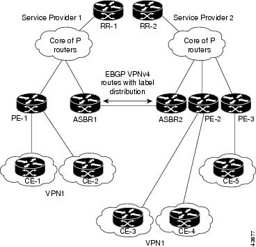
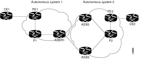
Figure 1 illustrates one MPLS VPN consisting of two separate autonomous systems. Each autonomous system operates under different administrative control and runs a different IGP. Service providers exchange routing information through eBGP border edge routers (ASBR1, ASBR2).
Figure 1 eBGP Connection Between Two MPLS VPN Interautonomous Systems with ASBRs Exchanging VPN-IPv4 Addresses
Table 2 describes the process to transmit information in an Inter-As configuration with ASBRs exchanging VPN-IPv4 addresses.
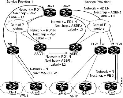
VPN Routing Information Exchange in an MPLS VPN Inter-AS with ASBRs Exchanging VPN-IPv4 Addresses
Autonomous systems exchange VPN routing information (routes and labels) to establish connections. To control connections between autonomous systems, the PE routers and eBGP border edge routers maintain a Label Forwarding Information Base (LFIB).
The LFIB manages the labels and routes that the PE routers and eBGP border edge routers receive during the exchange of VPN information.
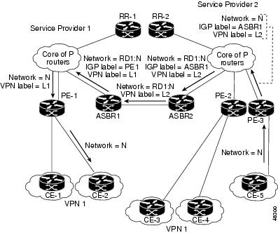
Figure 2 illustrates the exchange of VPN route and label information between autonomous systems. The autonomous systems use the following guidelines to exchange VPN routing information:
•
–
–
–
•
•
Figure 2 Exchanging Routes and Labels Between MPLS VPN Inter-AS Systems with ASBRs Exchanging VPN-IPv4 Addresses
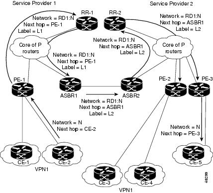
Figure 3 illustrates the exchange of VPN route and label information between autonomous systems. The only difference is that ASBR2 is configured with the redistribute connected command, which propagates the host routes to all PEs. The redistribute connected command is necessary because ASBR2 is not configured to change the next-hop address.
Figure 3 Exchanging Routes and Labels with the redistributed connected Command in an MPLS VPN Inter-AS with ASBRs Exchanging VPN-IPv4 Addresses
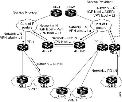
Packet Forwarding Between MPLS VPN Interautonomous Systems with ASBRs Exchanging VPN-IPv4 Addresses
Figure 4 illustrates how packets are forwarded between autonomous systems in an interprovider network using the following packet forwarding method.
Packets are forwarded to their destination by means of MPLS. Packets use the routing information stored in the LFIB of each PE router and eBGP border edge router.
The service provider VPN backbone uses dynamic label switching to forward labels.
Each autonomous system uses standard multilevel labeling to forward packets between the edges of the autonomous system routers (for example, from CE-5 to PE-3). Between autonomous systems, only a single level of labeling is used, corresponding to the advertised route.
A data packet carries two levels of labels when traversing the VPN backbone:
•
•
Figure 4 Packet Forwarding Between MPLS VPN Interautonomous Systems with ASBRs Exchanging VPN-IPv4 Addresses
Figure 5 shows the same packet forwarding method, except the eBGP router (ASBR1) forwards the packet without reassigning it a new label.
Figure 5 Forwarding Packets Without a New Label Assignment Between MPLS VPN Interautonomous Systems with ASBRs Exchanging VPN-IPv4 Addresses
Confederation Configuration for MPLS VPN Inter-AS with ASBRs Exchanging VPN-IPv4 Addresses
A confederation is multiple subautonomous systems grouped together. A confederation reduces the total number of peer devices in an autonomous system. A confederation divides an autonomous system into subautonomous systems and assigns a confederation identifier to the autonomous systems. A VPN can span service providers running in separate autonomous systems or in multiple subautonomous systems that form a confederation.
In a confederation, each subautonomous system is fully meshed with other subautonomous systems. The subautonomous systems communicate using an IGP, such as Open Shortest Path First (OSPF) or Intermediate System-to-Intermediate System (IS-IS). Each subautonomous system also has an eBGP connection to the other subautonomous systems. The confederation eBGP (CeBGP) border edge routers forward next-hop-self addresses between the specified subautonomous systems. The next-hop-self address forces the BGP to use a specified address as the next hop rather than letting the protocol choose the next hop.
You can configure a confederation with separate subautonomous systems in either of two ways:
•
•
Note
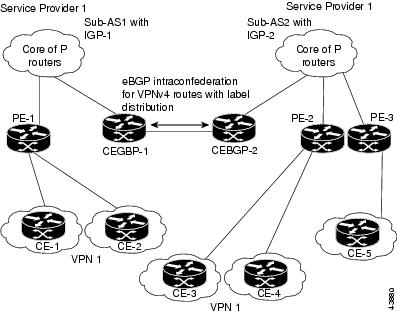
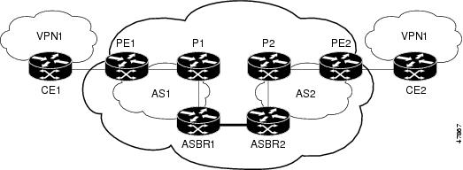
Figure 6 illustrates a typical MPLS VPN confederation configuration. In this confederation configuration:
•
•
IGP-1 and IGP-2 know the addresses of CeBGP-1 and CeBGP-2.
Figure 6 eBGP Connection Between Two Subautonomous Systems in a Confederation
In this confederation configuration:
•
•
•
Load Sharing with MPLS VPN Inter-AS ASBRs Exchanging VPN-IPv4 Addresses
Before the MPLS VPN—Multipath Support for Inter-AS VPNs feature, if multiple paths existed across ASBRs, BGP executed the best path algorithm and marked only one of the paths as the best path. This path was added to the routing table and became the only path that was used for forwarding traffic between ASBRs.
The MPLS VPN—Multipath Support for Inter-AS VPNs feature extends the functionality of BGP so that it can pick one path as the best path and mark the other legitimate paths between ASBRs as multipath. This allows the load sharing of traffic among the different multipaths and the best path to reach the destination. No Routing Information Base (RIB) or Cisco Express Forwarding entries are associated with the VPN-IPv4 prefixes.
The MPLS VPN—Multipath Support for Inter-AS VPNs feature applies to ASBRs that do not have a VPN routing and forwarding (VRF) instance configuration. BGP installs a number of learned VPN-IPv4 prefixes into the MPLS forwarding table (LFIB). VPN-IPv4 entries in the LFIB consist of the Route Distinguisher (RD) and the IPv4 prefix and are called VPNv4 entries.
The maximum-paths command is used to set the number of parallel (equal-cost) routes that BGP installs in the routing table to configure multipath load sharing. The number of paths that can be configured is determined by the version of Cisco IOS software. The following list shows the limits:
•
•
•
The MPLS VPN—Multipath Support for Inter-AS VPNs feature requires that you configure the maximum-paths number-of-paths command in address family configuration mode.
Note
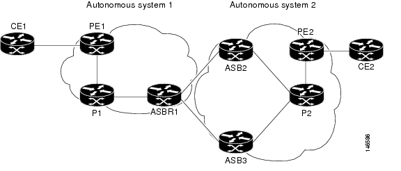
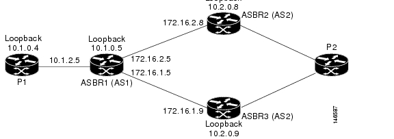
Figure 7 shows an example of VPNv4 load balancing for ASBRs in an Inter-AS network. In this example, ASBR1 load balances the traffic from the CE router CE1 to CE2 using the two available links—ASBR2 and ASBR3.
Figure 7 Example of VPNv4 Load Balancing for ASBRs in an Inter-AS Network
When you configure an ASBR for VPNv4 load balancing, you must configure the next-hop-self command for the iBGP peers. Without this command, the next hop that is propagated to the iBGP peer is the ASBR2 address or the ASBR3 address, depending on which one BGP selects as the best path. Configuring the next-hop-self command provides direct VPNv4 forwarding entries in the MPLS forwarding table for the VPNv4 prefixes learned from the remote ASBRs. VPNv4 forwarding entries are not created if you do not configure the next-hop-self command.
Note
How to Configure MPLS VPN—Interautonomous System Support
Perform the following tasks to configure MPLS VPN Inter-AS with ASBRs exchanging VPN-IPv4 addresses:
•
•
•
•
•
Configuring an eBGP ASBR to Exchange MPLS VPN-IPv4 Addresses
Perform one of the following tasks to configure an eBGP ASBR to exchange MPLS VPN-IPv4 routes with another autonomous system:
•
•
Configuring Peering with Directly Connected Interfaces Between ASBRs
Perform this task to configure peering with directly connected interfaces between ASBRs so that the ASBRs can distribute BGP routes with MPLS labels.
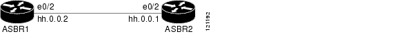
Figure 8 shows the configuration for the peering with directly connected interfaces between ASBRs. This configuration is used as the example in the tasks that follow.
Figure 8 Configuration for Peering with Directly Connected Interfaces Between ASBRs
Note
Note
SUMMARY STEPS
1.
2.
3.
4.
5.
6.
7.
8.
9.
DETAILED STEPS
Configuring Peering of the Loopback Interface of Directly Connected ASBRs
This functionality is provided with the release of the MPLS VPN—Interautonomous System Support feature on Cisco IOS Release 12.0(29)S and later releases. An eBGP session configured between loopbacks of directly connected ASBRs allows load sharing between loopback addresses.
Perform the following tasks in this section to configure peering of loopback interfaces of directly connected ASBRs:
•
•
•
•
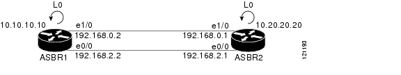
Figure 9 shows the loopback configuration for directly connected ASBR1 and ASBR2 routers. This configuration is used as the example in the tasks that follow.
Figure 9 Loopback Interface Configuration for Directly Connected ASBR1 and ASBR2 Routers
Configuring Loopback Interface Addresses for Directly Connected ASBRs
Perform the following task to configure loopback interface addresses for directly connected ASBRs.
Note
SUMMARY STEPS
1.
2.
3.
4.
5.
DETAILED STEPS
Examples
The following example shows the configuration of a loopback address for ASBR1:
configure terminalinterface loopback 0ip address 10.10.10.10 255.255.255.255The following example shows the configuration of a loopback address for ASBR2:
configure terminalinterface loopback 0ip address 10.20.20.20 255.255.255.255Configuring /32 Static Routes to the eBGP Neighbor Loopback
Perform the following task to configure /32 static routes to the eBGP neighbor loopback.
A /32 static route is established with the following commands:
Router(config)# ip route X.X.X.X 255.255.255.255 Ethernet 1/0 Y.Y.Y.YRouter(config)# ip route X.X.X.X 255.255.255.255 Ethernet 0/0 Z.Z.Z.ZWhere X.X.X.X is the neighboring loopback address and Ethernet 1/0 and Ethernet 0/0 are the links connecting the peering routers. Y.Y.Y.Y and Z.Z.Z.Z are the respective next-hop addresses on the interfaces.
Note
SUMMARY STEPS
1.
2.
3.
[distance] [name] [permanent] [tag tag]4.
DETAILED STEPS
Examples
The following example shows the configuration of a /32 static route from the ASBR1 router to the loopback address of the ASBR2 router:
configure terminalip route 10.20.20.20 255.255.255.255 e1/0 192.168.0.1ip route 10.20.20.20 255.255.255.255 e0/0 192.168.2.1The following example shows the configuration of a /32 static route from the ASBR2 router to the loopback address of the ASBR1 router:
configure terminalip route vrf vpn1 10.10.10.10 255.255.255.255 Ethernet 1/0 192.168.0.2ip route vrf vpn1 10.10.10.10 255.255.255.255 Ethernet 0/0 192.168.2.2Configuring Forwarding on the Directly Connected Interfaces
Perform this task to configure forwarding on the directly connected interfaces.
This task is required for sessions between loopbacks. In the "Configuring /32 Static Routes to the eBGP Neighbor Loopback" task, Ethernet 1/0 and Ethernet 0/0 are the connecting interfaces.
SUMMARY STEPS
1.
2.
3.
4.
5.
6.
7.
8.
DETAILED STEPS
Examples
The following example shows the configuration of BGP MPLS forwarding on the interfaces connecting the ASBR1 router with the ASBR2 router:
configure terminalinterface ethernet 1/0ip address 192.168.0.2 255.255.255.0mpls bgp forwardingexit!interface ethernet 0/0ip address 192.168.2.2 255.255.255.0mpls bgp forwardingexitThe following example shows the configuration of BGP MPLS forwarding on the interfaces connecting the ASBR2 router with the ASBR1 router:
configure terminalinterface ethernet 1/0ip address 192.168.0.1 255.255.255.0mpls bgp forwardingexit!interface ethernet 0/0ip address 192.168.2.1 255.255.255.0mpls bgp forwardingexitConfiguring an eBGP Session Between the Loopbacks
Perform the following tasks to configure an eBGP session between the loopbacks.
Note
SUMMARY STEPS
1.
2.
3.
4.
5.
6.
7.
interface-type interface-number8.
9.
10.
11.
12.
| interface interface | next-hop address | lsp-tunnel [tunnel-id]] [vrf vrf-name] [detail]DETAILED STEPS
Examples
The following example shows the configuration for VPNv4 sessions on the ASBR1 router:
configure terminalrouter bgp 200bgp log-neighbor-changesneighbor 10.20.20.20 remote-as 100neighbor 10.20.20.20 disable-connected-checkneighbor 10.20.20.20 update-source loopback 0!address-family vpnv4neighbor 10.20.20.20 activateneighbor 10.20.20.20 send-community extendedendThe following example shows the configuration for VPNv4 sessions on the ASBR2:
configure terminalrouter bgp 100bgp log-neighbor-changesneighbor 10.10.10.10 remote-as 200neighbor 10.10.10.10 disable-connected-checkneighbor 10.10.10.10 update-source Loopback 0!address-family vpnv4neighbor 10.10.10.10 activateneighbor 10.10.10.10 send-community extendedendConfiguring eBGP Routing to Exchange MPLS VPN Routes Between Subautonomous Systems in a Confederation
Perform this task to configure eBGP routing to exchange MPLS VPN routes between subautonomous systems in a confederation.
Note
Note
SUMMARY STEPS
1.
2.
3.
4.
5.
6.
7.
8.
9.
10.
11.
12.
DETAILED STEPS
Verifying Inter-AS for ASBRs Exchanging MPLS VPN-IPv4 Addresses
Perform this task to verify that Inter-AS for ASBRs Exchanging MPLS VPN-IPv4 addresses operates as you expected.
SUMMARY STEPS
1.
2.
3.
4.
5.
DETAILED STEPS
Step 1
Use this command to enable privileged EXEC mode. Enter your password if required. For example:
Router> enableRouter#Step 2
Use this command to verify that all VPNv4 information in the BGP table on the ASBR is as you expected. For example:
Router# show ip bgp vpnv4 allBGP table version is 99, local router ID is 172.16.10.3Status codes: s suppressed, d damped, h history, * valid, > best, i - internalOrigin coeds: i - IGP, e - EGP, ? incompleteNetwork Next Hop Metric LocPrf Weight PathRoute Distinguisher 100:1*> 10.1.1.0/24 10.1.1.1 50 100 0 200 ?* i 10.1.1.5 100 100 0 200 ?Route Distinguisher 100:2* 192.168.1.0/24 10.1.1.1 100 100 0 200 ?*>i 10.1.1.5 50 100 0 200 ?* 172.16.1.0/24 10.1.1.1 100 100 0 200 ?+>i 10.1.1.5 50 100 0 200 ?Route Distinguisher 200:1*>i172.16.1.0/24 10.1.1.2 50 100 0 200 ?*> 10.2.1.0/24 0.0.0.0. 0 32768 ?Route Distinguisher 200:2*>i172.16.1.0/24 10.1.1.5 50 100 0 200 ?*>i172.16.1.0/24 10.1.1.5 50 100 0 200 ?*> 10.2.1.0/24 0.0.0.0 0 32768 ?Step 3
Use this command to display information about all VPNv4 labels. For example:
Router# show ip bgp vpnv4 all labelsNetwork Next Hop In label/Out labelRoute Distinguisher 100:110.1.1.0/24 172.16.10.3 20/29Route Distinguisher 100:210.1.1.0/24 172.16.10.3 21/3510.2.1.0/24 172.16.10.3 24/36Route Distinguisher 200:110.30.1.0/24 10.1.1.2 23/164Route Distinguisher 200:210.31.1.0/24 10.1.1.2 27/165Step 4
Use this command to display the contents of the MPLS LFIB (such as VPNv4 prefix/length and BGP next-hop destination for the route) and see how the VPN-IPv4 LFIB entries appear. For example:
Router# show mpls forwarding-tableLocal Outgoing Prefix Bytes tag Outgoing Next Hoptag tag or VC or Tunnel Id switched interface33 33 10.120.4.0/24 0 Hs0/0 point2point35 27 100:12:10.200.0.1/32 \0 Hs0/0 point2pointIn this example, the Prefix field appears as a VPN-IPv4 RD, plus the prefix. If the value is longer than the width of the Prefix column (as illustrated in the last line of the example), the output automatically wraps onto the next line in the forwarding table, preserving column alignment.
Step 5
Use this command to exit to user EXEC mode. For example:
Router# exitRouter>
Configuring eBGP Multipath Load Sharing for MPLS VPN Inter-AS ASBRs Exchanging VPN-IPv4 Routes
Perform this task to configure eBGP multipath load sharing for MPLS VPN Inter-AS ASBRs exchanging VPN-IPv4 routes. This allows for more efficient use of the LSPs in an interautonomous system network because you can set up the load sharing of traffic among the different multipaths and the best path to reach the destination.
Restrictions for eBGP Multipath Load Sharing for MPLS VPN Inter-AS ASBRs Exchanging VPN-IPv4 Routes
The following restrictions apply to configuring multipath load sharing for MPLS VPN Inter-AS ASBRS exchanging VPN-IPv4 routes:
•
•
Figure 10 shows an eBGP multipath configuration for three VPN-IPv4 ASBRs. The links from ASBR1 to ASBR2 and ASBR3 have an eBGP VPN-IPv4 session configured. In Figure 10, eBGP multipath load sharing is configured on ASBR1. You configure the number of sessions from ASBR1 to ASBR2 and ASBR3 with the maximum-paths command in address family configuration mode.
Figure 10 eBGP Multipath Configuration for Three VPN-IPv4 ASBRs
The configurations in Figure 10 is used as an example for this task and for the task in the "Verifying eBGP Multipath Load Sharing for MPLS VPN Inter-AS ASBRs" section.
SUMMARY STEPS
1.
2.
3.
4.
5.
6.
7.
8.
9.
10.
11.
12.
13.
14.
15.
16.
17.
18.
19.
DETAILED STEPS
Step 1
enable
Example:Router> enable
Enables privileged EXEC mode.
•
Step 2
configure terminal
Example:Router# configure terminal
Enters global configuration mode.
Step 3
router bgp as-number
Example:Router(config)# router bgp 1
Configures an eBGP routing process and places the router in router configuration mode.
•
Step 4
no bgp default route-target filter
Example:Router(config-router)# no bgp default route-target filter
Disables BGP route-target community filtering.
All received VPN-IPv4 routes are accepted by the configured router. Accepting VPN-IPv4 routes is the desired behavior for a router configured as an ASBR.
Step 5
neighbor {ip-address | peer-group-name} remote-as as-number
Example:Router(config-router)# neighbor 10.1.0.4 remote-as 1
Adds an entry to the BGP or multiprotocol BGP neighbor table.
•
•
•
Step 6
neighbor {ip-address | peer-group-name} update-source interface-type interface-number
Example:Router(config-router)# neighbor 10.1.0.4 update-source loopback 0
Allows BGP sessions to use any operational interface for TCP connections.
•
•
•
This example shows how to set up BGP TCP connections for the specified neighbor with the IP address of the loopback interface rather than the best local address.
Step 7
neighbor {ip-address | peer-group-name} next-hop-self
Example:Router(config-router)# neighbor 10.1.0.4 next-hop-self
Configures the router as the next hop for a BGP neighbor or peer group.
•
•
Step 8
neighbor {ip-address | peer-group-name} remote-as as-number
Example:Router(config-router)# neighbor 172.16.1.9 remote-as 2
Adds an entry to the BGP or multiprotocol BGP neighbor table.
•
•
•
Step 9
Repeat Step 8 for each BGP neighbor.
—
Step 10
address-family vpnv4 [unicast]
Example:Router(config-router)# address-family vpnv4
Enters address family configuration mode.
•
This command configures a routing session to carry VPN-IPv4 addresses across the VPN backbone. Each address is globally unique by the addition of an 8-byte RD.
Step 11
neighbor {ip-address | peer-group-name} activate
Example:Router(config-router-af)# neighbor 10.1.0.4 activate
Enables the exchange of information with a neighboring router.
•
•
Step 12
neighbor {ip-address | peer-group-name} next-hop-self
Example:Router(config-router-af)# neighbor 10.1.0.4 next-hop-self
Configures the router as the next hop for a BGP neighbor or peer group.
•
•
Step 13
neighbor {ip-address | peer-group-name} send-community [both | standard | extended]
Example:Router(config-router-af)# neighbor 10.1.0.4 send-community extended
Specifies that a communities attribute should be sent to a BGP neighbor.
•
•
•
•
•
Step 14
neighbor {ip-address | peer-group-name | ipv6-address} activate
Example:Router(config-router-af)# neighbor 172.16.1.9 activate
Enables the exchange of information with a BGP neighbor.
•
•
•
This argument must be in the form documented in RFC 2373, where the address is specified in hexadecimal using 16-bit values between colons.
Step 15
neighbor {ip-address | peer-group-name} send-community [both | standard | extended]
Example:Router(config-router-af)# neighbor 172.16.1.9 send-community extended
Specifies that a communities attribute should be sent to a BGP neighbor.
•
•
•
•
•
Step 16
Repeat Steps 14 and 15 for each BGP neighbor.
—
Step 17
maximum-paths number-paths
Example:Router(config-router-af)# maximum-paths 2
Configures the maximum number of parallel routes that an IP routing protocol will install into the routing table.
•
•
Step 18
exit-address-family
Example:Router(config-router-af)# exit-address-family
Exits from address family configuration mode.
Step 19
end
Example:Router(config-router)# end
(Optional) Exits to privileged EXEC mode.
Examples
The following example shows the configuration for eBGP multipath for VPNv4 sessions on the ASBR1 router:
configure terminalrouter bgp 1no bgp default route-target filterneighbor 10.1.0.4 remote-as 1neighbor 10.1.0.4 update-source Loopback 0neighbor 10.1.0.4 next-hop-selfneighbor 172.16.1.9 remote-as 2neighbor 172.16.2.8 remote-as 2!address-family vpnv4neighbor 10.1.0.4 activateneighbor 10.1.0.4 next-hop-selfneighbor 10.1.0.4 send-community extendedneighbor 172.16.1.9 activateneighbor 172.16.1.9 send-community extendedneighbor 172.16.2.8 activateneighbor 172.16.2.8 send-community extendedmaximum-paths 2exit-address-familyendVerifying eBGP Multipath Load Sharing for MPLS VPN Inter-AS ASBRs
Perform the following task to verify that eBGP multipath load sharing for MPLS VPN Inter-AS ASBRs is operating as you expect.
The configurations in Figure 10 are used as an example for the task that follows.
SUMMARY STEPS
1.
2.
3.
4.
5.
6.
DETAILED STEPS
Step 1
Use this command to enable privileged EXEC mode. Enter your password if required. For example:
Router> enableRouter#Step 2
Use this command to verify that all peers are up. for example:
Router# show ip bgp vpnv4 all summaryNeighbor V AS MsgRcvd MsgSent TblVer InQ OutQ Up/Down State/PfxRcd10.1.0.4 4 1 87 86 5 0 0 01:24:56 2172.16.1.9 4 2 88 88 5 0 0 01:25:49 2172.16.2.8 4 2 88 88 5 0 0 01:25:49 2The output shows that all peers expected to be up are up and sending and receiving messages.
Step 3
Use this command to verify that BGP has paths from both remote ASBRs. For example:
Router# show ip bgp vpnv4 allNetwork Next Hop Metric LocPrf Weight Path..Route Distinguisher: 1:105*>i192.168.0.1/32 10.1.0.3 11 100 0 ?*> 192.168.0.2/32 172.16.2.8 0 2 ?* 172.16.1.9 0 2 ?*>i192.168.1.0 10.1.0.3 0 100 0 ?*> 192.168.2.0 172.16.2.8 0 2 ?* 172.16.1.9 0 2 ?The bold entries in the output confirm that BGP has a path to ASBR2 (172.16.2.8) and to ASBR3 (172.16.1.9).
Step 4
Use this command to verify that paths are marked as multipath. For example:
Router# show ip bgp vpnv4 192.168.2.0BGP routing table entry for 1:105:192.168.2.0/24, version 3Paths: (2 available, best #1, no table)Advertised to update-groups:2 32172.16.2.8 from 172.16.2.8 (10.2.0.8)Origin incomplete, localpref 100, valid, external, multipath, bestExtended Community: RT:1:100 OSPF DOMAIN ID:0x0005:0x0000000A0200OSPF RT:0.0.0.0:2:0 OSPF ROUTER ID:192.168.2.2:512,mpls labels in/out 21/252172.16.1.9 from 172.16.1.9 (10.2.0.9)Origin incomplete, localpref 100, valid, external, multipathExtended Community: RT:1:100 OSPF DOMAIN ID:0x0005:0x0000000A0200OSPF RT:0.0.0.0:2:0 OSPF ROUTER ID:192.168.2.2:512,mpls labels in/out 21/25In the output, the "multipath" and "mpls labels in/out 21/25" are in bold text for example purposes only.
Step 5
Use this command to verify that MPLS forwarding is properly set up and counters are increasing when traffic is present. For example:
Router# show mpls forwarding-tableLocal Outgoing Prefix Bytes Label Outgoing Next HopLabel Label or VC or Tunnel Id Switched interface..16 Pop Label 172.16.1.9/32 0 Et1/0 172.16.1.917 Pop Label 172.16.2.8/32 0 Et2/0 172.16.2.818 Pop Label 10.1.1.0/24 0 Et0/0 10.1.2.419 16 10.1.0.3/32 0 Et0/0 10.1.2.420 Pop Label 10.1.0.4/32 0 Et0/0 10.1.2.421 25 1:105:192.168.2.0/24 \26658 Et1/0 172.16.1.925 1:105:192.168.2.0/24 \1180 Et2/0 172.16.2.822 24 1:105:192.168.0.2/32 \15740 Et1/0 172.16.1.924 1:105:192.168.0.2/32 \0 Et2/0 172.16.2.823 19 1:105:192.168.0.1/32 \15638 Et0/0 10.1.2.424 20 1:105:192.168.1.0/24 \32740 Et0/0 10.1.2.4Step 6
Use this command to exit to user EXEC mode. For example:
Router# exitRouter>
Configuration Examples for MPLS VPN—Interautonomous System Support
This section provides the following configuration examples:
•
•
Configuring Inter-AS with ASBRs Exchanging VPN-IPv4 Addresses: Example
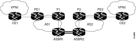
The network topology in Figure 11 shows two autonomous systems, which are configured as follows:
•
•
•
•
•
•
Figure 11 Configuring Two Autonomous Systems
Configuration for Autonomous System 1, CE1 Example for Two Autonomous Systems
The following example shows how to configure the CE1 router in VPN1 in a topology with two autonomous systems (see Figure 11):
!hostname CE1!interface Loopback 1ip address 192.168.0.1 255.255.255.255!interface Ethernet 1/0description Link to PE1ip address 192.168.1.1 255.255.255.0!router ospf 1log-adjacency-changesnetwork 192.168.0.0 0.0.255.255 area 0!endConfiguration for Autonomous System 1, PE1 Example for Two Autonomous Systems
The following example shows how to configure the PE1 router in autonomous system 1 in a topology with two autonomous systems (see Figure 11):
!hostname PE1!ip cef!ip vrf VPN1rd 1:105route-target export 1:100route-target import 1:100!interface Loopback 0ip address 10.1.0.3 255.255.255.255!interface Ethernet 0/0description Link to CE1ip vrf forwarding VPN1ip address 192.168.1.2 255.255.255.0!interface Ethernet 1/0description Link to P1ip address 10.1.1.3 255.255.255.0mpls ip!router ospf 10 vrf VPN1log-adjacency-changesredistribute bgp 1 metric 100 subnetsnetwork 192.168.0.0 0.0.255.255 area 0!router ospf 1log-adjacency-changesnetwork 10.0.0.0 0.255.255.255 area 0!router bgp 1no synchronizationbgp log-neighbor-changesneighbor R peer-groupneighbor R remote-as 1no neighbor R transport path-mtu-discoveryneighbor R update-source Loopback 0neighbor 10.1.0.4 peer-group Rno auto-summary!address-family vpnv4neighbor R send-community extendedneighbor 10.1.0.4 activateexit-address-family!address-family ipv4 vrf VPN1redistribute ospf 10 vrf VPN1no auto-summaryno synchronizationexit-address-family!endConfiguration for Autonomous System 1, P1 Example for Two Autonomous Systems
The following example shows how to configure the P1 router in autonomous system 1 in a topology with two autonomous systems (see Figure 11):
!hostname P1!ip cef!interface Loopback 0ip address 10.1.0.4 255.255.255.255!interface Ethernet 0/0description Link to PE1ip address 10.1.1.4 255.255.255.0mpls ip!interface Ethernet 1/0description Link to ASBR1ip address 10.1.2.4 255.255.255.0mpls ip!router ospf 1log-adjacency-changesnetwork 10.0.0.0 0.255.255.255 area 0!router bgp 1no synchronizationbgp log-neighbor-changesneighbor R peer-groupneighbor R remote-as 1no neighbor R transport path-mtu-discoveryneighbor R update-source Loopback 0neighbor R route-reflector-clientneighbor 10.1.0.3 peer-group Rneighbor 10.1.0.5 peer-group Rno auto-summary!address-family vpnv4neighbor R send-community extendedneighbor R route-reflector-clientneighbor 10.1.0.3 activateneighbor 10.1.0.5 activateexit-address-family!endConfiguration for Autonomous System 1, ASBR1 Example for Two Autonomous Systems
The following example shows how to configure ASBR1 in autonomous system 1 in a topology with two autonomous systems (see Figure 11):
hostname ASBR1!ip cef!interface Loopback 0ip address 10.1.0.5 255.255.255.255!interface Ethernet 0/0description Link to P1ip address 10.1.2.5 255.255.255.0mpls ip!interface Ethernet 1/0description Link to ASBR2ip address 172.16.0.1 255.255.255.255mpls bgp forwarding!router ospf 1log-adjacency-changesredistribute connected subnetsnetwork 10.0.0.0 0.255.255.255 area 0!router bgp 1no synchronizationno bgp default route-target filterbgp log-neighbor-changesneighbor R peer-groupneighbor R remote-as 1no neighbor R transport path-mtu-discoveryneighbor R update-source Loopback 0neighbor 10.1.0.4 peer-group Rneighbor 172.16.0.2 remote-as 2no auto-summary!address-family vpnv4neighbor R send-community extendedneighbor R next-hop-selfneighbor 10.1.0.4 activateneighbor 172.16.0.2 activateneighbor 172.16.0.2 send-community extendedexit-address-family!endConfiguration for Autonomous System 2, ASBR2 Example for Two Autonomous Systems
The following example shows how to configure ASBR2 in autonomous system 2 in a topology with two autonomous systems (see Figure 11):
!hostname ASBR2!ip cef!interface Loopback 0ip address 10.2.0.8 255.255.255.255ip router isis!interface Ethernet 0/0description Link to ASBR1ip address 172.16.0.2 255.255.255.255mpls bgp forwarding!interface Serial 2/0description Link to P2ip address 10.2.2.8 255.255.255.0ip router isismpls ipno fair-queueserial restart-delay 0!router isisnet 49.0002.0000.0000.0003.00!router bgp 2no synchronizationno bgp default route-target filterbgp log-neighbor-changesneighbor 10.2.0.7 remote-as 2neighbor 10.2.0.7 update-source Loopback 0neighbor 10.2.0.7 next-hop-selfneighbor 172.16.0.1 remote-as 1no auto-summary!address-family vpnv4neighbor 10.2.0.7 activateneighbor 10.2.0.7 send-community extendedneighbor 10.2.0.7 next-hop-selfneighbor 172.16.0.1 activateneighbor 172.16.0.1 send-community extendedexit-address-family!endConfiguration for Autonomous System 2, P2 Example for Two Autonomous Systems
The following example shows how to configure the P2 router in autonomous system 2 in a topology with two autonomous systems (see Figure 11):
!hostname P2!ip cef!interface Loopback 0ip address 10.2.0.7 255.255.255.255ip router isis!interface Ethernet 1/0description Link to PE2ip address 10.2.1.7 255.255.255.0ip router isismpls ip!interface Serial 2/0description Link to ASBR2ip address 10.2.2.7 255.255.255.0ip router isismpls ipno fair-queueserial restart-delay 0!router isisnet 49.0002.0000.0000.0008.00!router bgp 2no synchronizationbgp log-neighbor-changesneighbor R peer-groupneighbor R remote-as 2no neighbor R transport path-mtu-discoveryneighbor R update-source Loopback 0neighbor R route-reflector-clientneighbor 10.2.0.6 peer-group Rneighbor 10.2.0.8 peer-group Rno auto-summary!address-family vpnv4neighbor R send-community extendedneighbor R route-reflector-clientneighbor 10.2.0.6 activateneighbor 10.2.0.8 activateexit-address-family!endConfiguration for Autonomous System 2, PE2 Example for Two Autonomous Systems
The following example shows how to configure the PE2 router in autonomous system 2 in a topology with two autonomous systems (see Figure 11):
!hostname PE2!ip cef!ip vrf VPN1rd 1:105route-target export 1:100route-target import 1:100!interface Loopback 0ip address 10.2.0.6 255.255.255.255ip router isis!interface Ethernet 0/0description Link to P2ip address 10.2.1.6 255.255.255.0ip router isismpls ip!interface Serial 2/0description Link to CE2ip vrf forwarding VPN1ip address 192.168.2.2 255.255.255.0no fair-queueserial restart-delay 0!router ospf 10 vrf VPN1log-adjacency-changesredistribute bgp 2 subnetsnetwork 192.168.0.0 0.0.255.255 area 0!router isisnet 49.0002.0000.0000.0009.00!router bgp 2no synchronizationbgp log-neighbor-changesneighbor 10.2.0.7 remote-as 2neighbor 10.2.0.7 update-source Loopback 0no auto-summary!address-family vpnv4neighbor 10.2.0.7 activateneighbor 10.2.0.7 send-community extendedexit-address-family!address-family ipv4 vrf VPN1redistribute connectedredistribute ospf 10 vrf VPN1no auto-summaryno synchronizationexit-address-family!endConfiguration for Autonomous System 2, CE2 Example for Two Autonomous Systems
The following example shows how to configure the CE2 router in autonomous system 2 in a topology with two autonomous systems (see Figure 11):
!hostname CE2!interface Loopback 0ip address 192.168.0.2 255.255.255.255!interface Serial 2/0description Link to PE2ip address 192.168.2.1 255.255.255.0no fair-queueserial restart-delay 0!router ospf 1log-adjacency-changesnetwork 192.168.0.0 0.0.255.255 area 0!endConfiguring Inter-AS with ASBRs Exchanging VPN-IPv4 Addresses in a Confederation: Example
The network topology in Figure 12 shows a single Internet service provider (ISP), which is partitioning the backbone with confederations. The autonomous system number of the provider is 100. The two autonomous systems run their own IGPs and are configured as follows:
•
•
•
•
•
•
Figure 12 Configuring Two Autonomous Systems in a Confederation
Inter-AS Confederation Configuration for Autonomous System 1, CE1 Example
The following example shows how to configure CE1 in VPN1 in an Inter-AS confederation (see Figure 12):
!hostname CE1!interface Loopback 1ip address 192.168.0.1 255.255.255.255!interface Ethernet 1/0description Link to PE1ip address 192.168.1.1 255.255.255.0!router ospf 1log-adjacency-changesnetwork 192.168.0.0 0.0.255.255 area 0!endInter-AS Confederation Configuration for Autonomous System 1, PE1 Example
The following example shows how to configure PE1 in autonomous system 1 in an Inter-AS confederation (see Figure 12):
hostname PE1!ip cef!ip vrf VPN1rd 1:105route-target export 1:100route-target import 1:100!interface Loopback 0ip address 10.1.0.3 255.255.255.255!interface Ethernet 0/0description Link to CE1ip vrf forwarding VPN1ip address 192.168.1.2 255.255.255.0!interface Ethernet 1/0description Link to P1ip address 10.1.1.3 255.255.255.0mpls ip!router ospf 10 vrf VPN1log-adjacency-changesredistribute bgp 1 metric 100 subnetsnetwork 192.168.0.0 0.0.255.255 area 0!router ospf 1log-adjacency-changesnetwork 10.0.0.0 0.255.255.255 area 0!router bgp 1no synchronizationbgp log-neighbor-changesbgp confederation identifier 100neighbor R peer-groupneighbor R remote-as 1no neighbor R transport path-mtu-discoveryneighbor R update-source Loopback 0neighbor 10.1.0.4 peer-group Rno auto-summary!address-family vpnv4neighbor R send-community extendedneighbor 10.1.0.4 activateexit-address-family!address-family ipv4 vrf VPN1redistribute ospf 10 vrf VPN1no auto-summaryno synchronizationexit-address-family!endInter-AS Confederation Configuration for Autonomous System 1, P1 Example
The following example shows how to configure P1 in autonomous system 1 in a confederation topology (see Figure 12):
!hostname P1!ip cef!interface Loopback 0ip address 10.1.0.4 255.255.255.255!interface Ethernet 0/0description Link to PE1ip address 10.1.1.4 255.255.255.0mpls ip!interface Ethernet 1/0description Link to ASBR1ip address 10.1.2.4 255.255.255.0mpls ip!router ospf 1log-adjacency-changesnetwork 10.0.0.0 0.255.255.255 area 0!router bgp 1no synchronizationbgp log-neighbor-changesbgp confederation identifier 100neighbor R peer-groupneighbor R remote-as 1no neighbor R transport path-mtu-discoveryneighbor R update-source Loopback 0neighbor R route-reflector-clientneighbor 10.1.0.3 peer-group Rneighbor 10.1.0.5 peer-group Rno auto-summary!address-family vpnv4neighbor R send-community extendedneighbor R route-reflector-clientneighbor 10.1.0.3 activateneighbor 10.1.0.5 activateexit-address-family!endInter-AS Confederation Configuration for Autonomous System 1, ASBR1 Example
The following example shows how to configure ASBR1 in autonomous system 1 in a confederation topology (see Figure 12):
!hostname ASBR1!ip cef!interface Loopback 0ip address 10.1.0.5 255.255.255.255!interface Ethernet 0/0description Link to P1ip address 10.1.2.5 255.255.255.0mpls ip!interface Ethernet 1/0description Link to ASBR2ip address 172.16.0.1 255.255.255.255mpls bgp forwarding!router ospf 1log-adjacency-changesredistribute connected subnetsnetwork 10.0.0.0 0.255.255.255 area 0!router bgp 1no synchronizationno bgp default route-target filterbgp log-neighbor-changesbgp confederation identifier 100bgp confederation peers 2neighbor R peer-groupneighbor R remote-as 1no neighbor R transport path-mtu-discoveryneighbor R update-source Loopback 0neighbor 10.1.0.4 peer-group Rneighbor 172.16.0.2 remote-as 2neighbor 172.16.0.2 next-hop-selfno auto-summary!address-family vpnv4neighbor R send-community extendedneighbor R next-hop-selfneighbor 10.1.0.4 activateneighbor 172.16.0.2 activateneighbor 172.16.0.2 send-community extendedneighbor 172.16.0.2 next-hop-selfexit-address-family!endInter-AS Confederation Configuration for Autonomous System 2, ASBR2 Example
The following example shows how to configure ASBR2 in autonomous system 2 in a confederation topology (see Figure 12):
!hostname ASBR2!ip cef!interface Loopback 0ip address 10.2.0.8 255.255.255.255ip router isis!interface Ethernet 0/0description Link to ASBR1ip address 172.16.0.2 255.255.255.255mpls bgp forwarding!interface Serial 2/0description Link to P2ip address 10.2.2.8 255.255.255.0ip router isismpls ipno fair-queueserial restart-delay 0!router isisnet 49.0002.0000.0000.0003.00!router bgp 2no synchronizationno bgp default route-target filterbgp log-neighbor-changesbgp confederation identifier 100bgp confederation peers 1neighbor 10.2.0.7 remote-as 2neighbor 10.2.0.7 update-source Loopback 0neighbor 10.2.0.7 next-hop-selfneighbor 172.16.0.1 remote-as 1neighbor 172.16.0.1 next-hop-selfno auto-summary!address-family vpnv4neighbor 10.2.0.7 activateneighbor 10.2.0.7 send-community extendedneighbor 10.2.0.7 next-hop-selfneighbor 172.16.0.1 activateneighbor 172.16.0.1 send-community extendedneighbor 172.16.0.1 next-hop-selfexit-address-family!endInter-AS Confederation Configuration for Autonomous System 2, P2 Example
The following example shows how to configure P2 in autonomous system 2 in a confederation topology (see Figure 12):
!hostname P2!ip cef!interface Loopback 0ip address 10.2.0.7 255.255.255.255ip router isis!interface Ethernet 1/0description Link to PE2ip address 10.2.1.7 255.255.255.0ip router isismpls ip!interface Serial 2/0description Link to ASBR2ip address 10.2.2.7 255.255.255.0ip router isismpls ipno fair-queueserial restart-delay 0!router isisnet 49.0002.0000.0000.0008.00!router bgp 2no synchronizationbgp log-neighbor-changesbgp confederation identifier 100neighbor R peer-groupneighbor R remote-as 2no neighbor R transport path-mtu-discoveryneighbor R update-source Loopback 0neighbor R route-reflector-clientneighbor 10.2.0.6 peer-group Rneighbor 10.2.0.8 peer-group Rno auto-summary!address-family vpnv4neighbor R send-community extendedneighbor R route-reflector-clientneighbor 10.2.0.6 activateneighbor 10.2.0.8 activateexit-address-family!endInter-AS Confederation Configuration for Autonomous System 2, PE2 Example
The following example shows how to configure PE2 in autonomous system 2 in a confederation topology (see Figure 12):
!hostname PE2!ip cef!ip vrf VPN1rd 1:105route-target export 1:100route-target import 1:100!interface Loopback 0ip address 10.2.0.6 255.255.255.255ip router isis!interface Ethernet 0/0description Link to P2ip address 10.2.1.6 255.255.255.0ip router isismpls ip!interface Serial 2/0description Link to CE2ip vrf forwarding VPN1ip address 192.168.2.2 255.255.255.0no fair-queueserial restart-delay 0!router ospf 10 vrf VPN1log-adjacency-changesredistribute bgp 2 subnetsnetwork 192.168.0.0 0.0.255.255 area 0!router isisnet 49.0002.0000.0000.0009.00!router bgp 2no synchronizationbgp log-neighbor-changesbgp confederation identifier 100neighbor 10.2.0.7 remote-as 2neighbor 10.2.0.7 update-source Loopback 0no auto-summary!address-family vpnv4neighbor 10.2.0.7 activateneighbor 10.2.0.7 send-community extendedexit-address-family!address-family ipv4 vrf VPN1redistribute connectedredistribute ospf 10 vrf VPN1no auto-summaryno synchronizationexit-address-family!endInter-AS Confederation Configuration for Autonomous System 2, CE2 Example
The following example shows how to configure CE2 in VPN1 in a confederation topology (see Figure 12):
!hostname CE2!interface Loopback 0ip address 192.168.0.2 255.255.255.255!interface Serial 2/0description Link to PE2ip address 192.168.2.1 255.255.255.0no fair-queueserial restart-delay 0!router ospf 1log-adjacency-changesnetwork 192.168.0.0 0.0.255.255 area 0!endConfiguring eBGP Multipath Load Sharing for MPLS VPN Inter-AS ASBRs Exchanging VPN-IPv4 Routes: Example
This section includes examples that show how to configure eBGP multipath load sharing for MPLS VPN Inter-AS ASBRS that exchange VPN-IPv4 routes. These configurations support the MPLS VPN—Multipath Support for Inter-AS VPNs feature.
The network topology in Figure 13 shows two autonomous systems, which are configured as follows:
•
•
•
•
•
•
Figure 13 Configuring eBGP Multipath Load Sharing Between MPLS Inter-AS ASBRs Exchanging VPN-IPv4 Routes
The following examples shows how to configure eBGP multipath load sharing for MPLS VPN Inter-AS ASBRs that exchange VPN-IPv4 routes. This section includes sample configurations for P1, ASBR1, ASBR2, and P2 routers.
Multipath Support for Inter-AS VPNs Configuration for Autonomous System 1, CE1 Example
The following example shows how to configure CE1 in VPN1 for the MPLS VPN—Multipath Support for Inter-AS VPNs feature (see Figure 13):
!hostname CE1!interface Loopback 1ip address 192.168.0.1 255.255.255.255!interface Ethernet 1/0description Link to PE1ip address 192.168.1.1 255.255.255.0!router ospf 1log-adjacency-changesnetwork 192.168.0.0 0.0.255.255 area 0!endMultipath Support for Inter-AS VPNs Configuration for Autonomous System 1, PE1 Example
The following example shows how to configure PE1 in autonomous system 1 for the MPLS VPN—Multipath Support for Inter-AS VPNs feature (see Figure 13):
!hostname PE1!ip cef!ip vrf V1rd 1:105route-target export 1:100route-target import 1:100!interface Loopback 0ip address 10.1.0.3 255.255.255.255!interface Ethernet 0/0description Link to CE1ip vrf forwarding V1ip address 192.168.1.2 255.255.255.0!interface Ethernet 1/0description Link to P1ip address 10.1.1.3 255.255.255.0mpls ip!router ospf 10 vrf V1log-adjacency-changesredistribute bgp 1 metric 100 subnetsnetwork 192.168.0.0 0.0.255.255 area 0!router ospf 1log-adjacency-changesnetwork 10.0.0.0 0.255.255.255 area 0!router bgp 1no synchronizationbgp log-neighbor-changesneighbor 10.1.0.4 remote-as 1no neighbor 10.1.0.4 transport path-mtu-discoveryneighbor 10.1.0.4 update-source Loopback 0no auto-summary!address-family vpnv4neighbor 10.1.0.4 activateneighbor 10.1.0.4 send-community extendedexit-address-family!address-family ipv4 vrf V1redistribute ospf 10 vrf V1no auto-summaryno synchronizationexit-address-family!endMultipath Support for Inter-AS VPNs Configuration for Autonomous System 1, P1 Example
The following example shows how to configure P1 in autonomous system 1 for the MPLS VPN—Multipath Support for Inter-AS VPNs feature (see Figure 13):
!hostname P1!ip cef!interface Loopback 0ip address 10.1.0.4 255.255.255.255!interface Ethernet 0/0description Link to PE1ip address 10.1.1.4 255.255.255.0mpls ip!interface Ethernet 1/0description Link to ASBR1ip address 10.1.2.4 255.255.255.0mpls ip!router ospf 1log-adjacency-changesnetwork 10.0.0.0 0.255.255.255 area 0!router bgp 1no synchronizationbgp log-neighbor-changesneighbor R peer-groupneighbor R remote-as 1no neighbor R transport path-mtu-discoveryneighbor R update-source Loopback 0neighbor R route-reflector-clientneighbor 10.1.0.3 peer-group Rneighbor 10.1.0.5 peer-group Rno auto-summary!address-family vpnv4neighbor R send-community extendedneighbor R route-reflector-clientneighbor 10.1.0.3 activateneighbor 10.1.0.5 activateexit-address-family!endMultipath Support for Inter-AS VPNs Configuration for Autonomous System 1, ASBR1 Example
The following example shows how to configure ASBR1 in autonomous system 1 for the MPLS VPN—Multipath Support for Inter-AS VPNs feature (see Figure 13):
hostname ASBR1!ip cef!interface Loopback 0ip address 10.1.0.5 255.255.255.255!interface Ethernet 0/0description Core link to P1ip address 10.1.2.5 255.255.255.0mpls ip!interface Ethernet 1/0description Link to ASBR2ip address 172.16.2.5 255.255.255.0mpls bgp forwarding!interface Serial 3/0description Link to ASBR3ip address 172.16.1.5 255.255.255.0mpls bgp forwardingserial restart-delay 0!!router ospf 1log-adjacency-changesnetwork 10.0.0.0 0.255.255.255 area 0!router bgp 1no synchronizationno bgp default route-target filterbgp log-neighbor-changesneighbor 10.1.0.4 remote-as 1neighbor 172.16.1.9 remote-as 2neighbor 172.16.2.8 remote-as 2no auto-summary!address-family vpnv4neighbor 10.1.0.4 activateneighbor 10.1.0.4 send-community extendedneighbor 10.1.0.4 next-hop-selfneighbor 172.16.1.9 activateneighbor 172.16.1.9 send-community extendedneighbor 172.16.2.8 activateneighbor 172.16.2.8 send-community extendedmaximum-paths 2exit-address-family!endMultipath Support for Inter-AS VPNs Configuration for Autonomous System 2, ASBR2 Example
The following example shows how to configure ASBR2 in autonomous system 2 for the MPLS VPN—Multipath Support for Inter-AS VPNs feature (see Figure 13):
!hostname ASBR2!ip cef!interface Loopback 0ip address 10.2.0.8 255.255.255.255!interface Loopback 1no ip addressshutdown!interface Ethernet 0/0description Link to ASBR1ip address 172.16.2.8 255.255.255.0mpls bgp forwarding!interface Serial 2/0description Link to P2ip address 10.2.2.8 255.255.255.0mpls ipno fair-queueserial restart-delay 0!router ospf 1log-adjacency-changesredistribute connected subnetsnetwork 10.0.0.0 0.255.255.255 area 0!router bgp 2no synchronizationno bgp default route-target filterbgp log-neighbor-changesneighbor 10.2.0.7 remote-as 2neighbor 10.2.0.7 update-source Loopback 0neighbor 10.2.0.7 next-hop-selfneighbor 172.16.2.5 remote-as 1no auto-summary!address-family vpnv4neighbor 10.2.0.7 activateneighbor 10.2.0.7 send-community extendedneighbor 10.2.0.7 next-hop-selfneighbor 172.16.2.5 activateneighbor 172.16.2.5 send-community extendedexit-address-family!endMultipath Support for Inter-AS VPNs Configuration for Autonomous System 2, ASBR3 Example
The following example shows how to configure ASBR3 in autonomous system 2 for the MPLS VPN—Multipath Support for Inter-AS VPNs feature (see Figure 13):
!hostname ASBR3!ip cef!interface Loopback 0ip address 10.2.0.9 255.255.255.255!interface Ethernet 0/0description Link to ASBR1ip address 172.16.1.9 255.255.255.0mpls bgp forwarding!interface Serial 3/0description Link to P2ip address 10.2.3.9 255.255.255.0mpls ipno fair-queueserial restart-delay 0!router ospf 1log-adjacency-changesredistribute connected subnetsnetwork 10.0.0.0 0.255.255.255 area 0!router bgp 2no synchronizationno bgp default route-target filterbgp log-neighbor-changesneighbor 10.2.0.7 remote-as 2neighbor 10.2.0.7 update-source Loopback 0neighbor 10.2.0.7 next-hop-selfneighbor 172.16.1.5 remote-as 1no auto-summary!address-family vpnv4neighbor 10.2.0.7 activateneighbor 10.2.0.7 send-community extendedneighbor 10.2.0.7 next-hop-selfneighbor 172.16.1.5 activateneighbor 172.16.1.5 send-community extendedexit-address-family!endMultipath Support for Inter-AS VPNs Configuration for Autonomous System 2, P2 Example
The following example shows how to configure P2 in autonomous system 2 for the MPLS VPN—Multipath Support for Inter-AS VPNs feature (see Figure 13):
!hostname P2!ip cef!interface Loopback 0ip address 10.2.0.7 255.255.255.255!interface Ethernet 1/0description Link to PE2ip address 10.2.1.7 255.255.255.0mpls ip!interface Serial 2/0description Link to ASBR2ip address 10.2.2.7 255.255.255.0mpls ipno fair-queueserial restart-delay 0!interface Serial 3/0description Link to ASBR3ip address 10.2.3.7 255.255.255.0mpls ipserial restart-delay 0!router ospf 1log-adjacency-changesnetwork 10.0.0.0 0.255.255.255 area 0!router bgp 2no synchronizationbgp log-neighbor-changesneighbor R peer-groupneighbor R remote-as 2no neighbor R transport path-mtu-discoveryneighbor R update-source Loopback 0neighbor R route-reflector-clientneighbor 10.2.0.6 peer-group Rneighbor 10.2.0.8 peer-group Rneighbor 10.2.0.9 peer-group Rno auto-summary!address-family vpnv4neighbor R send-community extendedneighbor R route-reflector-clientneighbor 10.2.0.6 activateneighbor 10.2.0.8 activateneighbor 10.2.0.9 activateexit-address-family!end!Multipath Support for Inter-AS VPNs Configuration for Autonomous System 2, PE2 Example
The following example shows how to configure PE2 in autonomous system 2 for the MPLS VPN—Multipath Support for Inter-AS VPNs feature (see Figure 13):
hostname PE2!ip cef!ip vrf V1rd 1:105route-target export 1:100route-target import 1:100!interface Loopback 0ip address 10.2.0.6 255.255.255.255!interface Ethernet 0/0description Link to P2ip address 10.2.1.6 255.255.255.0mpls ip!interface Serial 2/0description Link to CE2ip vrf forwarding V1ip address 192.168.2.2 255.255.255.0no fair-queueserial restart-delay 0!router ospf 10 vrf V1log-adjacency-changesredistribute bgp 2 subnetsnetwork 192.168.0.0 0.0.255.255 area 0!router ospf 1log-adjacency-changesnetwork 10.0.0.0 0.255.255.255 area 0!router bgp 2no synchronizationbgp log-neighbor-changesneighbor 10.2.0.7 remote-as 2neighbor 10.2.0.7 update-source Loopback 0no auto-summary!address-family vpnv4neighbor 10.2.0.7 activateneighbor 10.2.0.7 send-community extendedexit-address-family!address-family ipv4 vrf V1redistribute connectedredistribute ospf 10 vrf V1no auto-summaryno synchronizationexit-address-family!endMultipath Support for Inter-AS VPNs Configuration for Autonomous System 2, CE2 Example
The following example shows how to configure CE2 in VPN1 for the MPLS VPN—Multipath Support for Inter-AS VPNs feature (see Figure 13):
hostname CE2!interface Loopback 0ip address 192.168.0.2 255.255.255.255!interface Serial 2/0description Link to PE2ip address 192.168.2.1 255.255.255.0no fair-queueserial restart-delay 0!router ospf 1log-adjacency-changesnetwork 192.168.0.0 0.0.255.255 area 0endAdditional References
The following sections provide references related to configuring MPLS VPN—Inter-AS support.
Related Documents
Configuration tasks for basic MPLS VPNs
Configuration tasks for enhanced VPN traffic management including BGP commands
Configuration tasks for MPLS VPN Inter-AS system exchanging IPv4 routes and MPLS labels
Configuration tasks for MPLS VPN Carrier Supporting Carrier
Information about monitoring MPLS VPNs with MIBs
Configuration tasks for assigning an ID number to a VPN
Configuration tasks for MPLS and MPLS applications
Cisco IOS Multiprotocol Label Switching Configuration Guide, Release 12.4
Standards
No new or modified standards are supported by this feature, and support for existing standards has not been modified by this feature.
—
MIBs
RFCs
Technical Assistance
Command Reference
This section documents only commands that are new or modified.
•
bgp default route-target filter
To enable automatic Border Gateway Protocol (BGP) default route-target community filtering, use the bgp default route-target filter command in router configuration mode. To disable automatic BGP route-target community filtering, use the no form of this command.
bgp default route-target filter
no bgp default route-target filter
Syntax Description
This command has no arguments or keywords.
Command Default
Automatic BGP default route-target community filtering is enabled.
Command Modes
Router configuration (config-router)
Command History
Usage Guidelines
Use the bgp default route-target filter command to control the distribution of Virtual Private Network (VPN) routing information through the list of VPN route-target communities.
When you use the no form of this command, all received VPN-IPv4 routes are accepted by the configured router. Accepting VPN-IPv4 routes is the desired behavior for a router configured as an autonomous system border edge router or as a customer edge (CE) BGP border edge router.
If you configure the router for BGP route-target community filtering, all received exterior BGP (eBGP) VPN-IPv4 routes are discarded when those routes do not contain a route-target community value that matches the import list of any configured VPN routing and forwarding (VRFs) instances. This is the desired behavior for a router configured as a provider edge (PE) router.
Note
Examples
In the following example, BGP route-target filtering is disabled for autonomous system 120:
Router(config)# router bgp 120Router(config-router)# no bgp default route-target filterRelated Commands
mpls bgp forwarding
To enable an interface to receive Multiprotocol Label Switching (MPLS) packets when the signaling of MPLS labels is through the use of the Border Gateway Protocol (BGP), use the mpls bgp forwarding command in interface configuration mode. To disable an interface from receiving MPLS packets when the signaling of MPLS labels is through the use of the BGP, use the no form of this command.
mpls bgp forwarding
no mpls bgp forwarding
Syntax Description
This command has no arguments or keywords.
Command Default
MPLS forwarding by BGP is not enabled.
Command Modes
Interface configuration (config-if)
Command History
Usage Guidelines
Use the mpls bgp forwarding command when you want to enable MPLS forwarding on directly connected loopback interfaces. This command is automatically generated by BGP for directly connected nonloopback neighbors.
Examples
The following example shows how to configure BGP to enable MPLS forwarding on a directly connected loopback interface, Ethernet 0/0:
Router(config)# interface ethernet 0/0Router(config-if)# mpls forwardingRelated Commands
Feature Information for MPLS VPN—Interautonomous System Support
Table 3 lists the release history for this feature.
Not all commands may be available in your Cisco IOS software release. For release information about a specific command, see the command reference documentation.
For information on a feature in this technology that is not documented here, see the "MPLS Layer 3 VPN Features Roadmap" module.
Cisco IOS software images are specific to a Cisco IOS software release, a feature set, and a platform. Use Cisco Feature Navigator to find information about platform support and Cisco IOS software image support. To access Cisco Feature Navigator, go to http://www.cisco.com/go/cfn. An account on Cisco.com is not required.
Note
Table 3 Feature Information for MPLS VPN—Interautonomous System Support
MPLS VPN—Interautonomous System Support
12.1(5)T, 12.0(16)ST, 12.0(17)ST,
12.0(22)S, 12.0(23)S, 12.2(13)T, 12.0(24)S, 12.2(14)S, 12.0(29)S, 12.2(33)SRA,
12.2(33)SXHThe MPLS VPN—Interautonomous System Support feature allows an MPLS VPN to span service providers and autonomous systems. This feature module explains how to configure the Inter-AS using the ASBRs to exchange VPNv4 Addresses.
In 12.1(5)T, this feature was introduced.
In 12.0(16)ST, support for the Cisco 12000 series 4-Port OC-3c/STM-1c ATM line card (4-Port OC-3 ATM) and the Cisco 12000 series 4-Port OC-3c/STM-1c POS/SDH line card (4-port OC-3 POS) was added.
In 12.0(17)ST, support for the Cisco 12000 series was added (See Table 1 for the Cisco 12000 series line cards supported.)
In 12.0(22)S, support for the Cisco 12000 series, the Cisco 10000 series edge services routers (ESRs), and the Cisco 10720 Internet routers was added. (See Table 1 for the Cisco 12000 series line cards supported.)
In 12.0(23)S, support was added for the Cisco 12000 series 8-port OC-3c/STM-1c ATM line card (8-Port OC-3 ATM) and the Cisco 12000 series 3-port Gigabit Ethernet line card (3-Port GbE).
This feature was integrated into Cisco IOS Release 12.2(13)T.
In 12.0(24)S, support was added for the Cisco 12000 series 1-port 10-Gigabit Ethernet line card (1-Port 10-GbE) and the Cisco 12000 series modular Gigabit Ethernet/Fast Ethernet line card (modular GbE/FE) and this feature was implemented on Cisco IOS 12.0(24)S.
This feature was integrated into Cisco IOS Release 12.2(14)S and implemented on Cisco 7200 and Cisco 7500 series routers.
In 12.0(29)S, support was added for eBGP sessions between loopbacks of directly connected MPLS-enabled routers to provide for load sharing between neighbors.
This feature was integrated into Cisco IOS Release 12.2(33)SRA. Support was added for load balancing of Virtual Private Network (VPN) traffic for VPNv4 peering.
This feature was integrated into Cisco IOS Release 12.2(33)SXH.
MPLS VPN - Loadbalancing support for Inter-AS and CSC VPNs
12.0(29)S, 12.2(33)SRA
This feature allows MPLS VPN Inter-AS and MPLS VPN Carrier Supporting Carrier (CSC) networks to load share traffic between adjacent LSRs that are connected by multiple links. The LSRs can be a pair of ASBRs or a CSC-PE and a CSC-CE. Using directly connected loopback peering allows load sharing at the IGP level, so more than one BGP session is not needed between the LSRs. No other label distribution mechanism is needed between the adjacent LSRs than BGP.
MPLS VPN—Multipath Support for Inter-AS VPNs
12.2(33)SRA
12.2(33)SXHThis feature supports Virtual Private Network (VPN)v4 multipath for Autonomous System Border Routers (ASBRs) in the interautonomous system (Inter-AS) Multiprotocol Label Switching (MPLS) VPN environment. It allows load balancing of VPN traffic when you use the VPNv4 peering model for Inter-AS VPNs.
Glossary
autonomous system—A collection of networks under a common administration sharing a common routing strategy.
BGP—Border Gateway Protocol. An interdomain routing protocol that exchanges network reachability information with other BGP systems (which may be within the same autonomous system or between multiple autonomous systems).
CeBGP—confederation exterior Border Gateway Protocol. A BGP between routers located within different subautonomous systems of a confederation. See eBGP and iBGP.
CE router—customer edge router. A router that is part of a customer network and that interfaces to a provider edge (PE) router. CE routers do not recognize associated MPLS VPNs.
confederation—An autonomous system divided into multiple, separate subautonomous systems and classified as a single unit.
eBGP—exterior Border Gateway Protocol. A BGP between routers located within different autonomous systems. When two routers, located in different autonomous systems, are more than one hop away from one another, the eBGP session between the two routers is considered a multihop BGP.
iBGP—interior Border Gateway Protocol. A BGP between routers within the same autonomous system.
IGP—Interior Gateway Protocol. Internet protocol used to exchange routing information within a single autonomous system. Examples of common Internet IGP protocols include IGRP, OSPF, IS-IS, and RIP.
LFIB—Label Forwarding Information Base. Data structure used in MPLS to hold information about incoming and outgoing labels and associated Forwarding Equivalence Class (FEC) packets.
MPLS—Multiprotocol Label Switching. The name of the IETF working group responsible for label switching, and the name of the label switching approach it has standardized.
NLRI—Network Layer Reachability Information. The BGP sends routing update messages containing NLRI to describe a route and how to get there. In this context, an NLRI is a prefix. A BGP update message carries one or more NLRI prefixes and the attributes of a route for the NLRI prefixes; the route attributes include a BGP next hop gateway address and extended community values.
PE router—provider edge router. A router that is part of a service provider's network. It is connected to a customer edge (CE) router and all MPLS VPN processing occurs in the PE router.
RD—route distinguisher. An 8-byte value that is concatenated with an IPv4 prefix to create a unique VPN-IPv4 prefix.
VPN—Virtual Private Network. A secure MPLS-based network that shares resources on one or more physical networks (typically implemented by one or more service providers). A VPN contains geographically dispersed sites that can communicate securely over a shared backbone network.
VRF—VPN routing and forwarding instance. Routing information that defines a Virtual Private Network (VPN) site that is attached to a provider edge (PE) router. A VRF consists of an IP routing table, a derived forwarding table, a set of interfaces that use the forwarding table, and a set of rules and routing protocols that determine what goes into the forwarding table.
CCVP, the Cisco logo, and the Cisco Square Bridge logo are trademarks of Cisco Systems, Inc.; Changing the Way We Work, Live, Play, and Learn is a service mark of Cisco Systems, Inc.; and Access Registrar, Aironet, BPX, Catalyst, CCDA, CCDP, CCIE, CCIP, CCNA, CCNP, CCSP, Cisco, the Cisco Certified Internetwork Expert logo, Cisco IOS, Cisco Press, Cisco Systems, Cisco Systems Capital, the Cisco Systems logo, Cisco Unity, Enterprise/Solver, EtherChannel, EtherFast, EtherSwitch, Fast Step, Follow Me Browsing, FormShare, GigaDrive, HomeLink, Internet Quotient, IOS, iPhone, IP/TV, iQ Expertise, the iQ logo, iQ Net Readiness Scorecard, iQuick Study, LightStream, Linksys, MeetingPlace, MGX, Networking Academy, Network Registrar, Packet, PIX, ProConnect, ScriptShare, SMARTnet, StackWise, The Fastest Way to Increase Your Internet Quotient, and TransPath are registered trademarks of Cisco Systems, Inc. and/or its affiliates in the United States and certain other countries.
All other trademarks mentioned in this document or Website are the property of their respective owners. The use of the word partner does not imply a partnership relationship between Cisco and any other company. (0705R)
Any Internet Protocol (IP) addresses used in this document are not intended to be actual addresses. Any examples, command display output, and figures included in the document are shown for illustrative purposes only. Any use of actual IP addresses in illustrative content is unintentional and coincidental.
© 2000-2004, 2006-2007 Cisco Systems, Inc. All rights reserved.