Downloads |
 Feedback Feedback
|
Table Of Contents
MPLS VPN—Interautonomous System Support
Routing Between Autonomous Systems
Exchanging VPN Routing Information
Routing Between Subautonomous Systems in a Confederation
Related Features and Technologies
Supported Standards, MIBs, and RFCs
Configuring EBGP Routing for the Exchange of VPN Routes Between Autonomous Systems
Displaying VPN-IPv4 LFIB Entries
Configuring EBGP Routing to Exchange VPN Routes Between Autonomous Systems Examples
Configuration for Autonomous System 1, CE1 Example
Configuration for Autonomous System 1, PE1 Example
Configuration for Autonomous System 1, P1 Example
Configuration for Autonomous System 1, EBGP1 Example
Configuration for Autonomous System 2, EBGP2 Example
Configuration for Autonomous System 2, P2 Example
Configuration for Autonomous System 2, PE2 Example
Configuration for Autonomous System 2, CE2 Example
bgp default route-target filter
MPLS VPN—Interautonomous System Support
Feature History
12.1(5)T
This document was introduced.
12.0(16)ST
This feature was integrated into Cisco IOS Release 12.0(16)ST. Support for the Cisco 12000 Series Four-Port OC-3c/STM-1c ATM Line Card (4-Port OC-3 ATM) and the Cisco 12000 Series Four-Port OC-3c/STM-1c POS/SDH Line Card (4-Port OC-3 POS) was added.
12.0(17)ST
This feature was integrated into Cisco IOS Release 12.0(17)ST. Support for the Cisco 12000 series was added (See Table 1 for the Cisco 12000 series line cards supported).
12.0(22)S
This feature was integrated into Cisco IOS Release 12.0(22)S. Support for the Cisco 12000 series, the Cisco 10000 series edge services routers (ESRs), and the Cisco 10720 Internet Routers was added. (See Table 1 for the Cisco 12000 series line cards supported).
This feature module explains how to provide Multiprotocol Label Switching Virtual Private Network (MPLS VPN) services that can span multiple autonomous systems (ASs) and VPN service providers. This document includes the following sections:
•
Supported Standards, MIBs, and RFCs
Feature Overview
The MPLS VPN—Interautonomous System Support feature allows an MPLS VPN to span service providers and autonomous systems.
As VPNs grow, their requirements expand. In some cases, VPNs need to reside on different autonomous systems in different geographic areas. (An autonomous system is a single network or group of networks that is controlled by a common system administration group and that uses a single, clearly defined routing protocol.) Also, some VPNs need to extend across multiple service providers (overlapping VPNs). Regardless of the complexity and location of the VPNs, the connection between autonomous systems must be seamless to the customer.
The MPLS VPN—Interautonomous System Support feature provides seamless integration of autonomous systems and service providers. Separate autonomous systems from different service providers can communicate by exchanging IPv4 Network Layer Reachability Information (NLRI) in the form of VPN-IPv4 addresses. The autonomous systems' border edge routers use Exterior Border Gateway Protocol (EBGP) to exchange that information. Then, an Interior Gateway Protocol (IGP) distributes the network layer information for VPN-IPv4 prefixes throughout each VPN and each autonomous system. Routing information uses the following protocols:
•
•
An MPLS VPN with interautonomous system support allows a service provider to provide to customers scalable Layer 3 VPN services, such as web hosting, application hosting, interactive learning, electronic commerce, and telephony service. A VPN service provider supplies a secure, IP-based network that shares resources on one or more physical networks.
The primary function of an EBGP is to exchange network reachability information between autonomous systems, including information about the list of autonomous system routes. The autonomous systems use EGBP border edge routers to distribute the routes, which include label switching information. Each border edge router rewrites the next-hop and MPLS labels. See the section "Routing Between Autonomous Systems" for more information.
Interautonomous system configurations supported in an MPLS VPN can include:
•
•
Benefits
The MPLS VPN—Interautonomous System Support feature provides the following benefits.
Allows a VPN to Cross More Than One Service Provider Backbone
Service providers, running separate autonomous systems, can jointly offer MPLS VPN services to the same end customer. A VPN can begin at one customer site and traverse different VPN service provider backbones before arriving at another site of the same customer. Previous MPLS VPN could only traverse a single BGP autonomous system service provider backbone. This feature allows multiple autonomous systems to form a continuous (and seamless) network between customer sites of a service provider.
Allows a VPN to Exist in Different Areas
A service provider can create a VPN in different geographic areas. Having all VPN traffic flow through one point (between the areas) allows for better rate control of network traffic between the areas.
Allows Confederations to Optimize IBGP Meshing
IBGP meshing in an autonomous system is more organized and manageable. You can divide an autonomous system into multiple, separate subautonomous systems and then classify them into a single confederation (even though the entire VPN backbone appears as a single autonomous system). This capability allows a service provider to offer MPLS VPNs across the confederation because it supports the exchange of labeled VPN-IPv4 NLRI between the subautonomous systems that form the confederation.
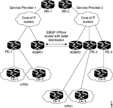
Routing Between Autonomous Systems
Figure 1 illustrates one MPLS VPN consisting of two separate autonomous systems. Each autonomous system operates under different administrative control and runs a different IGP. Service providers exchange routing information through EBGP border edge routers (ASBR1, ASBR2).
Figure 1 EBGP Connection Between Two Autonomous Systems
This configuration uses the following process to transmit information:
Step 1
Step 2
Step 3
•
•
Step 4
•
•
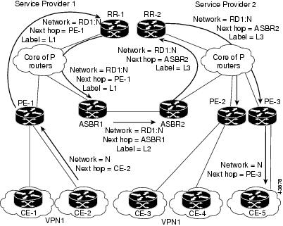
Exchanging VPN Routing Information
Autonomous systems exchange VPN routing information (routes and labels) to establish connections. To control connections between autonomous systems, the PE routers and EBGP border edge routers maintain a label forwarding information base (LFIB). The LFIB manages the labels and routes that the PE routers and EBGP border edge routers receive during the exchange of VPN information.
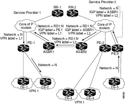
Figure 2 illustrates the exchange of VPN route and label information between autonomous systems. The autonomous systems use the following guidelines to exchange VPN routing information:
•
–
–
–
•
•
Figure 2 Exchanging Routes and Labels Between Autonomous Systems in an Interprovider VPN Network
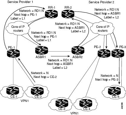
Figure 3 illustrates the exchange of VPN route and label information between autonomous systems. The only difference is that ASBR2 is configured with the redistribute connected command, which propagates the host routes to all PEs. The redistribute connected command is necessary because ASBR2 is not configured to change the next hop address.
Figure 3 Exchanging Routes and Labels Between Autonomous Systems in an Interprovider VPN Network with the redistributed connected Command
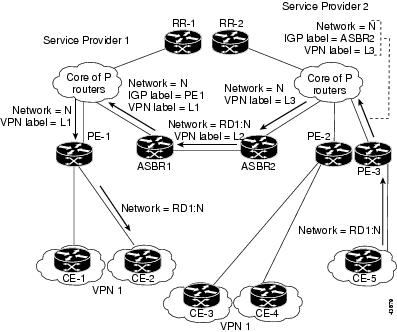
Packet Forwarding
Figure 4 illustrates how packets are forwarded between autonomous systems in an interprovider network using the following packet forwarding method.
Packets are forwarded to their destination by means of MPLS. Packets use the routing information stored in the LFIB of each PE router and EBGP border edge router.
The service provider VPN backbone uses dynamic label switching to forward labels.
Each autonomous system uses standard multilevel labeling to forward packets between the edges of the autonomous system routers (for example, from CE-5 to PE-3). Between autonomous systems, only a single level of labeling is used, corresponding to the advertised route.
A data packet carries two levels of labels when traversing the VPN backbone:
•
•
Figure 4 Forwarding Packets Between Autonomous Systems in an Interprovider VPN Network
Figure 5 illustrates shows the same packet forwarding method, except the EBGP router (ASBR1) forwards the packet without reassigning it a new label.
Figure 5 Forwarding Packets Between Autonomous Systems in an Interprovider VPN Network Without a New Label Assignment
Routing Between Subautonomous Systems in a Confederation
A VPN can span service providers running in separate autonomous systems or between multiple subautonomous systems that have been grouped together to form a confederation.
A confederation reduces the total number of peer devices in an autonomous system. A confederation divides an autonomous system into subautonomous systems and assigns a confederation identifier to the autonomous systems.
In a confederation, each subautonomous system is fully meshed with other subautonomous systems. The subautonomous systems communicate using an IGP, such as Open Shortest Path First (OSPF) or Intermediate System-to-Intermediate System (IS-IS). Each subautonomous system also has an EBGP connection to the other subautonomous systems. The confederation EBGP (CEBGP) border edge routers forward next-hop-self addresses between the specified subautonomous systems. The next-hop-self address forces the BGP to use a specified address as the next hop rather than letting the protocol choose the next hop.
You can configure a confederation with separate subautonomous systems in two ways:
•
•
Note
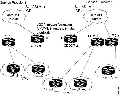
Figure 6 illustrates a typical MPLS VPN confederation configuration. In this confederation configuration:
•
•
•
Figure 6 EBGP Connection Between Two Subautonomous Systems in a Confederation
In this confederation configuration:
•
•
•
Restrictions
A VPN-IPv4 EBGP session must be configured between directly connected ASBRs. Multihop VPN-IPv4 EBGP is not supported.
Related Features and Technologies
The MPLS VPN—Interautonomous System Support feature is used with the VPN capabilities of MPLS. MPLS VPNs were introduced in Cisco IOS Release 12.0(5)T.
Related Documents
•
•
•
Supported Platforms
The following router platforms are supported at the service provider edge:
•
•
•
•
•
Table 1 lists the Cisco 12000 series line card support added for Cisco IOS Releases.
Determining Platform Support Through Cisco Feature Navigator
Cisco IOS software is packaged in feature sets that support specific platforms. To get updated information regarding platform support for this feature, access Cisco Feature Navigator. Cisco Feature Navigator dynamically updates the list of supported platforms as new platform support is added for the feature.
Cisco Feature Navigator is a web-based tool that enables you to determine which Cisco IOS software images support a specific set of features and which features are supported in a specific Cisco IOS image. You can search by feature or release. Under the release section, you can compare releases side by side to display both the features unique to each software release and the features in common.
To access Cisco Feature Navigator, you must have an account on Cisco.com. If you have forgotten or lost your account information, send a blank e-mail to cco-locksmith@cisco.com. An automatic check will verify that your e-mail address is registered with Cisco.com. If the check is successful, account details with a new random password will be e-mailed to you. Qualified users can establish an account on Cisco.com by following the directions at http://www.cisco.com/register.
Cisco Feature Navigator is updated regularly when major Cisco IOS software releases and technology releases occur. For the most current information, go to the Cisco Feature Navigator home page at the following URL:
Availability of Cisco IOS Software Images
Platform support for particular Cisco IOS software releases is dependent on the availability of the software images for those platforms. Software images for some platforms may be deferred, delayed, or changed without prior notice. For updated information about platform support and availability of software images for each Cisco IOS software release, refer to the online release notes or, if supported, Cisco Feature Navigator.
Supported Standards, MIBs, and RFCs
Standards
No new or modified standards are supported by this feature.
MIBs
No new or modified MIBs are supported by this feature.
To obtain lists of supported MIBs by platform and Cisco IOS release, and to download MIB modules, go to the Cisco MIB website on Cisco.com at the following URL:
http://www.cisco.com/public/sw-center/netmgmt/cmtk/mibs.shtml
RFCs
•
•
•
•
•
•
Standards
•
Prerequisites
The network must be properly configured for MPLS VPN operation before you configure interautonomous systems. Refer to the following documents for MPLS VPN network configuration details:
•
•
•
Configuration Tasks
To configure the exchange of VPN-IPv4 addresses between two or more autonomous systems or subautonomous systems in a confederation, perform the following tasks:
•
•
•
Before You Begin
Before you configure EBGP routing between autonomous systems or subautonomous systems in an MPLS VPN, ensure that you have properly configured all MPLS VPN routing instances and sessions. The configuration tasks outlined in this section build from those configuration tasks.
Perform (as appropriate to the existing network configuration) the following tasks as described in the Cisco IOS Switching Services Configuration Guide (the Configuring Multiprotocol Label Switching chapter).
•
•
•
•
Configuring EBGP Routing for the Exchange of VPN Routes Between Autonomous Systems
To configure an EBGP border edge router in an autonomous system to exchange VPN routes with another autonomous system, use the following commands starting in EXEC mode.
Note
Configuring EBGP Routing for the Exchange of VPN Routes Between Subautonomous Systems in a Confederation
To configure EBGP border edge router in a confederation to exchange VPN routes with another subautonomous system, use the following commands starting in EXEC mode.
Note
Note
Displaying VPN-IPv4 LFIB Entries
To display the VPN-IPv4 label forwarding information base (LFIB) entries at the border edge routers in the autonomous systems, use the following commands starting in EXEC mode:
The following is an example of how the VPN-IPv4 LFIB entries appear when you use the show tag-switching forwarding-table privileged EXEC command:
Router#show tag-switching forwarding-tableLocal Outgoing Prefix Bytes tag Outgoing Next Hoptag tag or VC or Tunnel Id switched interface33 33 10.120.4.0/24 0 Hs0/0 point2point35 27 100:12:10.200.0.1/32 \0 Hs0/0 point2point
Note
Configuration Examples
This section provides the following configuration examples:
•
Configuring EBGP Routing to Exchange VPN Routes Between Autonomous Systems Examples
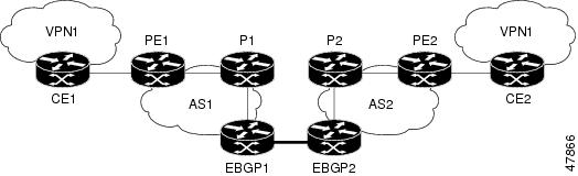
The network topology in Figure 7 shows two autonomous systems, which are configured as follows:
•
•
•
•
•
•
Figure 7 Configuring Two Autonomous Systems
Configuration for Autonomous System 1, CE1 Example
CE1: Burlington!interface Loopback1ip address 1.0.0.6 255.255.255.255!interface Serial1/3description Veritasno ip addressencapsulation frame-relayframe-relay intf-type dce!interface Serial1/3.1 point-to-pointdescription Veritasip address 1.6.2.1 255.255.255.252frame-relay interface-dlci 22!router ospf 1network 1.0.0.0 0.255.255.255 area 0Configuration for Autonomous System 1, PE1 Example
PE1: Veritas!ip cef!ip vrf V1rd 1:105route-target export 1:100route-target import 1:100!interface Serial0/0description Burlingtonno ip addressencapsulation frame-relayno fair-queueclockrate 2000000!interface Serial0/0.3 point-to-pointdescription Burlingtonip vrf forwarding V1ip address 1.6.2.2 255.255.255.252frame-relay interface-dlci 22!interface Ethernet0/1description Vermontip address 100.2.2.5 255.255.255.0tag-switching ip!router ospf 1log-adjacency-changesnetwork 100.0.0.0 0.255.255.255 area 0!router ospf 10 vrf V1log-adjacency-changesredistribute bgp 1 metric 100 subnetsnetwork 1.0.0.0 0.255.255.255 area 0!router bgp 1no synchronizationneighbor R peer-groupneighbor R remote-as 1neighbor R update-source Loopback0neighbor 100.0.0.2 peer-group Rno auto-summary!address-family ipv4 vrf V1redistribute ospf 10no auto-summaryno synchronizationexit-address-family!address-family vpnv4neighbor R activateneighbor R send-community extendedneighbor 100.0.0.2 peer-group Rno auto-summaryexit-address-familyConfiguration for Autonomous System 1, P1 Example
P1: Vermont!ip cef!interface Loopback0ip address 100.0.0.2 255.255.255.255!interface Ethernet0/1description Ogunquitip address 100.2.1.1 255.255.255.0tag-switching ip!interface FastEthernet2/0description Veritasip address 100.2.2.1 255.255.255.0duplex autospeed autotag-switching ip!router ospf 1log-adjacency-changesnetwork 100.0.0.0 0.255.255.255 area 0!router bgp 1no synchronizationbgp log-neighbor-changesneighbor R peer-groupneighbor R remote-as 1neighbor R update-source Loopback0neighbor R route-reflector-clientneighbor 100.0.0.4 peer-group Rneighbor 100.0.0.5 peer-group R!address-family vpnv4neighbor R activateneighbor R route-reflector-clientneighbor R send-community extendedneighbor 100.0.0.4 peer-group Rneighbor 100.0.0.5 peer-group Rexit-address-familyConfiguration for Autonomous System 1, EBGP1 Example
EBGP1: Ogunquit!ip cef!interface Loopback0ip address 100.0.0.4 255.255.255.255!interface Ethernet0/1description Vermontip address 100.2.1.40 255.255.255.0tag-switching ip!interface ATM1/0description Lowellno ip addressno atm scrambling cell-payloadno atm ilmi-keepalive!interface ATM1/0.1 point-to-pointdescription Lowellip address 12.0.0.1 255.255.255.252pvc 1/100!router ospf 1log-adjacency-changesredistribute connected subnetsnetwork 100.0.0.0 0.255.255.255 area 0!router bgp 1no synchronizationno bgp default route-target filterbgp log-neighbor-changesneighbor R peer-groupneighbor R remote-as 1neighbor R update-source Loopback0neighbor 12.0.0.2 remote-as 2neighbor 100.0.0.2 peer-group Rno auto-summary!address-family vpnv4neighbor R activateneighbor R send-community extendedneighbor 12.0.0.2 activateneighbor 12.0.0.2 send-community extendedneighbor 100.0.0.2 peer-group Rno auto-summaryexit-address-familyConfiguration for Autonomous System 2, EBGP2 Example
EBGP2: Lowell!ip cef!ip vrf V1rd 2:103route-target export 1:100route-target import 1:100!interface Loopback0ip address 200.0.0.3 255.255.255.255ip router isis!interface Loopback1ip vrf forwarding V1ip address 1.0.0.3 255.255.255.255!interface Serial0/0description Littletonno ip addressencapsulation frame-relayload-interval 30no fair-queueclockrate 2000000!interface Serial0/0.2 point-to-pointdescription Littletonip unnumbered Loopback0ip router isistag-switching ipframe-relay interface-dlci 23!interface ATM1/0description Ogunquitno ip addressatm clock INTERNALno atm scrambling cell-payloadno atm ilmi-keepalive!interface ATM1/0.1 point-to-pointdescription Ogunquitip address 12.0.0.2 255.255.255.252pvc 1/100!router isisnet 49.0002.0000.0000.0003.00!router bgp 2no synchronizationno bgp default route-target filterbgp log-neighbor-changesneighbor 12.0.0.1 remote-as 1neighbor 200.0.0.8 remote-as 2neighbor 200.0.0.8 update-source Loopback0neighbor 200.0.0.8 next-hop-self!address-family ipv4 vrf V1redistribute connectedno auto-summaryno synchronizationexit-address-family!address-family vpnv4neighbor 12.0.0.1 activateneighbor 12.0.0.1 send-community extendedneighbor 200.0.0.8 activateneighbor 200.0.0.8 next-hop-selfneighbor 200.0.0.8 send-community extendedexit-address-familyConfiguration for Autonomous System 2, P2 Example
P2: Littleton!ip cef!ip vrf V1rd 2:108route-target export 1:100route-target import 1:100!interface Loopback0ip address 200.0.0.8 255.255.255.255ip router isis!interface Loopback1ip vrf forwarding V1ip address 1.0.0.8 255.255.255.255!interface FastEthernet0/0description Paxip address 200.9.1.2 255.255.255.0ip router isistag-switching ip!interface Serial5/0description Lowellno ip addressencapsulation frame-relayframe-relay intf-type dce!interface Serial5/0.1 point-to-pointdescription Lowellip unnumbered Loopback0ip router isistag-switching ipframe-relay interface-dlci 23!router isisnet 49.0002.0000.0000.0008.00!router bgp 2no synchronizationbgp log-neighbor-changesneighbor R peer-groupneighbor R remote-as 2neighbor R update-source Loopback0neighbor R route-reflector-clientneighbor 200.0.0.3 peer-group Rneighbor 200.0.0.9 peer-group R!address-family ipv4 vrf V1redistribute connectedno auto-summaryno synchronizationexit-address-family!address-family vpnv4neighbor R activateneighbor R route-reflector-clientneighbor R send-community extendedneighbor 200.0.0.3 peer-group Rneighbor 200.0.0.9 peer-group Rexit-address-familyConfiguration for Autonomous System 2, PE2 Example
PE2: Pax!ip cef!ip vrf V1rd 2:109route-target export 1:100route-target import 1:100!interface Loopback0ip address 200.0.0.9 255.255.255.255ip router isis!interface Loopback1ip vrf forwarding V1ip address 1.0.0.9 255.255.255.255!interface Serial0/0description Bethelno ip addressencapsulation frame-relayframe-relay intf-type dceno fair-queueclockrate 2000000!interface Serial0/0.1 point-to-pointdescription Bethelip vrf forwarding V1ip unnumbered Loopback1frame-relay interface-dlci 24!interface FastEthernet0/1description Littletonip address 200.9.1.1 255.255.255.0ip router isistag-switching ip!router ospf 10 vrf V1log-adjacency-changesredistribute bgp 2 subnetsnetwork 1.0.0.0 0.255.255.255 area 0!router isisnet 49.0002.0000.0000.0009.00!router bgp 2no synchronizationbgp log-neighbor-changesneighbor 200.0.0.8 remote-as 2neighbor 200.0.0.8 update-source Loopback0!address-family ipv4 vrf V1redistribute connectedredistribute ospf 10no auto-summaryno synchronizationexit-address-familyaddress-family vpnv4neighbor 200.0.0.8 activateneighbor 200.0.0.8 send-community extendedexit-address-familyConfiguration for Autonomous System 2, CE2 Example
CE2: Bethel!interface Loopback0ip address 1.0.0.11 255.255.255.255!interface Serial0description Paxno ip addressencapsulation frame-relayno fair-queueclockrate 2000000!interface Serial0.1 point-to-pointdescription Paxip unnumbered Loopback0frame-relay interface-dlci 24!router ospf 1network 1.0.0.0 0.255.255.255 area 0Configuring EBGP Routing to Exchange VPN Routes Between Autonomous Systems in a Confederation Examples
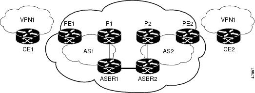
The network topology in Figure 8 shows a single Internet service provider (ISP), which is partitioning the backbone with confederations. The AS number of the provider is 100. The two autonomous systems run their own IGPs and are configured as follows:
•
•
•
•
•
•
Figure 8 Configuring Two Autonomous Systems in a Confederation
Configuration for Autonomous System 1, CE1 Example
CE1: Burlington!interface Loopback1ip address 1.0.0.6 255.255.255.255!interface Serial1/3description Veritasno ip addressencapsulation frame-relayframe-relay intf-type dce!interface Serial1/3.1 point-to-pointdescription Veritasip address 1.6.2.1 255.255.255.252frame-relay interface-dlci 22!router ospf 1network 1.0.0.0 0.255.255.255 area 0Configuration for Autonomous System 1, PE1 Example
PE1: Veritas!ip cef!ip vrf V1rd 1:105route-target export 1:100route-target import 1:100!interface Serial0/0description Burlingtonno ip addressencapsulation frame-relayno fair-queueclockrate 2000000!interface Serial0/0.3 point-to-pointdescription Burlingtonip vrf forwarding V1ip address 1.6.2.2 255.255.255.252frame-relay interface-dlci 22!interface Ethernet0/1description Vermontip address 100.2.2.5 255.255.255.0tag-switching ip!router ospf 1log-adjacency-changesnetwork 100.0.0.0 0.255.255.255 area 0!router ospf 10 vrf V1log-adjacency-changesredistribute bgp 1 metric 100 subnetsnetwork 1.0.0.0 0.255.255.255 area 0!router bgp 1no synchronizationbgp confederation identifier 100bgp confederation identifier 100neighbor R peer-groupneighbor R remote-as 1neighbor R update-source Loopback0neighbor 100.0.0.2 peer-group Rno auto-summary!address-family ipv4 vrf V1redistribute ospf 10no auto-summaryno synchronizationexit-address-family!address-family vpnv4neighbor R activateneighbor R send-community extendedneighbor 100.0.0.2 peer-group Rno auto-summaryexit-address-familyConfiguration for Autonomous System 1, P1 Example
P1: Vermont!ip cef!interface Loopback0ip address 100.0.0.2 255.255.255.255!interface Ethernet0/1description Ogunquitip address 100.2.1.1 255.255.255.0tag-switching ip!interface FastEthernet2/0description Veritasip address 100.2.2.1 255.255.255.0duplex autospeed autotag-switching ip!router ospf 1log-adjacency-changesnetwork 100.0.0.0 0.255.255.255 area 0!router bgp 1no synchronizationbgp log-neighbor-changesbgp confederation identifier 100neighbor R peer-groupneighbor R remote-as 1neighbor R update-source Loopback0neighbor R route-reflector-clientneighbor 100.0.0.4 peer-group Rneighbor 100.0.0.5 peer-group R!address-family vpnv4neighbor R activateneighbor R route-reflector-clientneighbor R send-community extendedneighbor 100.0.0.4 peer-group Rneighbor 100.0.0.5 peer-group Rexit-address-familyConfiguration for Autonomous System 1, EBGP1 Example
EBGP1: Ogunquit!ip cef!interface Loopback0ip address 100.0.0.4 255.255.255.255!interface Ethernet0/1description Vermontip address 100.2.1.40 255.255.255.0tag-switching ip!interface ATM1/0description Lowellno ip addressno atm scrambling cell-payloadno atm ilmi-keepalive!interface ATM1/0.1 point-to-pointdescription Lowellip address 12.0.0.1 255.255.255.252pvc 1/100!router ospf 1log-adjacency-changesredistribute connected subnetsnetwork 100.0.0.0 0.255.255.255 area 0!router bgp 1no synchronizationno bgp default route-target filterbgp log-neighbor-changesbgp confederation identifier 100bgp confederation peers 1neighbor R peer-groupneighbor R remote-as 1neighbor R update-source Loopback0neighbor 12.0.0.2 remote-as 2neighbor 12.0.0.2 next-hop-selfneighbor 100.0.0.2 peer-group Rno auto-summary!address-family vpnv4neighbor R activateneighbor R send-community extendedneighbor 12.0.0.2 activateneighbor 12.0.0.2 next-hop-selfneighbor 12.0.0.2 send-community extendedneighbor 100.0.0.2 peer-group Rno auto-summaryexit-address-familyConfiguration for Autonomous System 2, EBGP2 Example
EBGP2: Lowell!ip cef!ip vrf V1rd 2:103route-target export 1:100route-target import 1:100!interface Loopback0ip address 200.0.0.3 255.255.255.255ip router isis!interface Loopback1ip vrf forwarding V1ip address 1.0.0.3 255.255.255.255!interface Serial0/0description Littletonno ip addressencapsulation frame-relayload-interval 30no fair-queueclockrate 2000000!interface Serial0/0.2 point-to-pointdescription Littletonip unnumbered Loopback0ip router isistag-switching ipframe-relay interface-dlci 23!interface ATM1/0description Ogunquitno ip addressatm clock INTERNALno atm scrambling cell-payloadno atm ilmi-keepalive!interface ATM1/0.1 point-to-pointdescription Ogunquitip address 12.0.0.2 255.255.255.252pvc 1/100!router isisnet 49.0002.0000.0000.0003.00!router bgp 2no synchronizationno bgp default route-target filterbgp log-neighbor-changesbgp confederation identifier 100bgp confederation peers 1neighbor 12.0.0.1 remote-as 1neighbor 12.0.0.1 next-hop-selfneighbor 200.0.0.8 remote-as 2neighbor 200.0.0.8 update-source Loopback0neighbor 200.0.0.8 next-hop-self!address-family ipv4 vrf V1redistribute connectedno auto-summaryno synchronizationexit-address-family!address-family vpnv4neighbor 12.0.0.1 activateneighbor 12.0.0.1 next-hop-selfneighbor 12.0.0.1 send-community extendedneighbor 200.0.0.8 activateneighbor 200.0.0.8 next-hop-selfneighbor 200.0.0.8 send-community extendedexit-address-familyConfiguration for Autonomous System 2, P2 Example
P2: Littleton!ip cef!ip vrf V1rd 2:108route-target export 1:100route-target import 1:100!interface Loopback0ip address 200.0.0.8 255.255.255.255ip router isis!interface Loopback1ip vrf forwarding V1ip address 1.0.0.8 255.255.255.255!interface FastEthernet0/0description Paxip address 200.9.1.2 255.255.255.0ip router isistag-switching ip!interface Serial5/0description Lowellno ip addressencapsulation frame-relayframe-relay intf-type dce!interface Serial5/0.1 point-to-pointdescription Lowellip unnumbered Loopback0ip router isistag-switching ipframe-relay interface-dlci 23!router isisnet 49.0002.0000.0000.0008.00!router bgp 2no synchronizationbgp log-neighbor-changesbgp confederation identifier 100neighbor R peer-groupneighbor R remote-as 2neighbor R update-source Loopback0neighbor R route-reflector-clientneighbor 200.0.0.3 peer-group Rneighbor 200.0.0.9 peer-group R!address-family ipv4 vrf V1redistribute connectedno auto-summaryno synchronizationexit-address-family!address-family vpnv4neighbor R activateneighbor R route-reflector-clientneighbor R send-community extendedneighbor 200.0.0.3 peer-group Rneighbor 200.0.0.9 peer-group Rexit-address-familyConfiguration for Autonomous System 2, PE2 Example
PE2: Pax!ip cef!ip vrf V1rd 2:109route-target export 1:100route-target import 1:100!interface Loopback0ip address 200.0.0.9 255.255.255.255ip router isis!interface Loopback1ip vrf forwarding V1ip address 1.0.0.9 255.255.255.255!interface Serial0/0description Bethelno ip addressencapsulation frame-relayframe-relay intf-type dceno fair-queueclockrate 2000000!interface Serial0/0.1 point-to-pointdescription Bethelip vrf forwarding V1ip unnumbered Loopback1frame-relay interface-dlci 24!interface FastEthernet0/1description Littletonip address 200.9.1.1 255.255.255.0ip router isistag-switching ip!router ospf 10 vrf V1log-adjacency-changesredistribute bgp 2 subnetsnetwork 1.0.0.0 0.255.255.255 area 0!router isisnet 49.0002.0000.0000.0009.00!router bgp 2no synchronizationbgp log-neighbor-changesbgp confederation identifier 100neighbor 200.0.0.8 remote-as 2neighbor 200.0.0.8 update-source Loopback0!address-family ipv4 vrf V1redistribute connectedredistribute ospf 10no auto-summaryno synchronizationexit-address-familyaddress-family vpnv4neighbor 200.0.0.8 activateneighbor 200.0.0.8 send-community extendedexit-address-familyConfiguration for Autonomous System 2, CE2 Example
CE2: Bethel!interface Loopback0ip address 1.0.0.11 255.255.255.255!interface Serial0description Paxno ip addressencapsulation frame-relayno fair-queueclockrate 2000000!interface Serial0.1 point-to-pointdescription Paxip unnumbered Loopback0frame-relay interface-dlci 24!router ospf 1network 1.0.0.0 0.255.255.255 area 0Command Reference
This section documents the following new command related to interautonomous system MPLS VPN operation:
•
All other commands used with this feature are described in the following Cisco IOS documentation:
•
•
•
bgp default route-target filter
To enable automatic Border Gateway Protocol (BGP) route-target community filtering, use the bgp default route-target filter command in router configuration mode. To disable this feature, use the no form of this command.
bgp default route-target filter
no bgp default route-target filter
Syntax Description
This command has no arguments or keywords.
Defaults
This command is enabled by default.
Command Modes
Router configuration
Command History
Usage Guidelines
You use this command to control the distribution of VPN routing information through the list of VPN route-target communities.
When you use the no form of this command, all received VPN-IPv4 routes are accepted by the configured router. Accepting VPN-IPv4 routes is the desired behavior for a router configured as an autonomous system border edge router or as a Confederation Exterior Border Gateway Protocol (CEBGP) border edge router.
If you configure the router for BGP route-target community filtering, all received EBGP VPN-IPv4 routes are discarded when those routes do not contain a route-target community value that matches the import list of any configured VRFs. This is the desired behavior for a router configured as a PE router.
Note
Examples
In the following example, BGP route target filtering is disabled for autonomous system 120:
Router(config)# router bgp 120Router(config-router)# no bgp default route-target filterRelated Commands
Glossary
autonomous system—A collection of networks under a common administration sharing a common routing strategy.
BGP—Border Gateway Protocol. An interdomain routing protocol that exchanges network reachability information with other BGP systems (which may be within the same autonomous system or between multiple autonomous systems).
CEBGP—Confederation Exterior Border Gateway Protocol. A BGP between routers located within different subautonomous systems of a confederation. See EBGP and IBGP.
CE router—customer edge router. A router that is part of a customer network and that interfaces to a provider edge (PE) router. CE routers do not recognize associated MPLS VPNs.
confederation—An autonomous system divided into multiple, separate subautonomous systems and classified as a single unit.
EBGP—Exterior Border Gateway Protocol. A BGP between routers located within different autonomous systems. When two routers, located in different autonomous systems, are more than one hop away from one another, the EBGP session between the two routers is considered a multihop BGP.
IBGP—Interior Border Gateway Protocol. A BGP between routers within the same autonomous system.
IGP—Interior Gateway Protocol. Internet protocol used to exchange routing information within a single autonomous system. Examples of common Internet IGP protocols include IGRP, OSPF, IS-IS, and RIP.
LFIB—label forwarding information base. Data structure used in MPLS to hold information about incoming and outgoing labels and associated Forwarding Equivalence Class (FEC) packets.
MPLS—Multiprotocol Label Switching. The name of the IETF working group responsible for label switching, and the name of the label switching approach it has standardized.
NLRI—Network Layer Reachability Information. The BGP sends routing update messages containing NLRI to describe a route and how to get there. In this context, an NLRI is a prefix. A BGP update message carries one or more NLRI prefixes and the attributes of a route for the NLRI prefixes; the route attributes include a BGP next hop gateway address and extended community values.
PE router—provider edge router. A router that is part of a service provider's network. It is connected to a customer edge (CE) router and all MPLS VPN processing occurs in the PE router.
RD—route distinguisher. An 8-byte value that is concatenated with an IPv4 prefix to create a unique VPN-IPv4 prefix.
VPN—Virtual Private Network. A secure MPLS-based network that shares resources on one or more physical networks (typically implemented by one or more service providers). A VPN contains geographically dispersed sites that can communicate securely over a shared backbone network.
VRF table —VPN routing/forwarding table. A VRF consists of an IP routing table, a derived forwarding table, a set of interfaces that use the forwarding table, and a set of rules and routing protocols that determine what goes into the forwarding table. A VRF includes the routing information that defines a customer VPN site that is attached to a PE router.