Feedback Feedback
|
Table Of Contents
MPLS Traffic Engineering: Shared Risk Link Groups
MPLS Traffic Engineering: Shared Risk Link Groups
Prerequisites for MPLS Traffic Engineering: Shared Risk Link Groups
Restrictions for MPLS Traffic Engineering: Shared Risk Link Groups
Information About MPLS Traffic Engineering: Shared Risk Link Groups
How to Configure MPLS Traffic Engineering: Shared Risk Link Groups
Configuring the SRLG Membership of Each Link That Has a Shared Risk with Another Link
Verifying the MPLS Traffic Engineering: Shared Risk Link Groups Configuration
Configuration Examples for MPLS Traffic Engineering: Shared Risk Link Groups
Configuring the SRLG Membership of Each Link That Has a Shared Risk with Another Link: Example
MPLS Traffic Engineering: Shared Risk Link Groups
First Published: May 6, 2004Last Updated: May 31, 2007Shared Risk Link Groups (SRLGs) refer to situations where links in a network share a common fiber (or a common physical attribute). If one link fails, other links in the group may fail too. Links in the group have a shared risk.
The MPLS Traffic Engineering: Shared Risk Link Groups feature enhances backup tunnel path selection so that a backup tunnel avoids using links that are in the same SRLG as interfaces the backup tunnel is protecting.
History for the MPLS Traffic Engineering: Shared Risk Link Groups Feature
Finding Support Information for Platforms and Cisco IOS and Catalyst OS Software Images
Use Cisco Feature Navigator to find information about platform support and Cisco IOS and Catalyst OS software image support. To access Cisco Feature Navigator, go to http://www.cisco.com/go/cfn. An account on Cisco.com is not required.
Contents
•
MPLS Traffic Engineering: Shared Risk Link Groups
•
•
•
•
•
•
MPLS Traffic Engineering: Shared Risk Link Groups
Backup tunnels should avoid using links in the same SRLG as interfaces they are protecting. Otherwise, when the protected link fails the backup tunnel fails too.
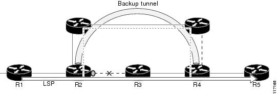
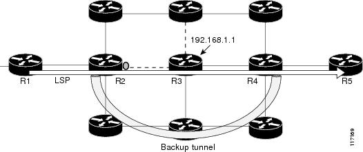
Figure 1 shows a primary label-switched path (LSP) from router R1 to router R5. The LSP protects against the failure of the R2-R3 link at R2 via a backup tunnel to R4. If the R2-R3 link fails, link protection reroutes the LSP along the backup tunnel. However, the R2-R3 link and one of the backup tunnel links are in the same SRLG. So if the R2-R3 link fails, the backup tunnel may fail too.
Figure 1 Backup Tunnel in the Same SRLG as the Interface It Is Protecting
The MPLS TE SRLG feature enhances backup tunnel path selection so a backup tunnel can avoid using links that are in the same SRLG as the interfaces it is protecting.
There are two ways for a backup tunnel to avoid the SRLGs of its protected interface:
•
•
Note
To activate the MPLS TE SRLG feature, you must do the following:
•
•
For a detailed explanation of the configuration steps, see the "How to Configure MPLS Traffic Engineering: Shared Risk Link Groups" section.
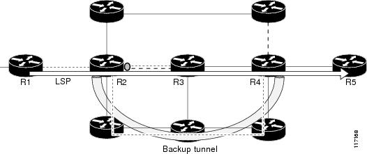
OSPF and Intermediate System-to-Intermediate System (IS-IS) flood the SRLG membership information (including other TE link attributes such as bandwidth availability and affinity) so that all routers in the network have the SRLG information for each link. With this topology information, routers can compute backup tunnel paths that exclude links having SRLGs in common with their protected interfaces. As shown in Figure 2, the backup tunnel avoids the link between R2 and R3, which shares an SRLG with the protected interface.
Figure 2 Backup Tunnel that Avoids SRLG of Protected Interface
Prerequisites for MPLS Traffic Engineering: Shared Risk Link Groups
•
•
Restrictions for MPLS Traffic Engineering: Shared Risk Link Groups
•
•
•
Information About MPLS Traffic Engineering: Shared Risk Link Groups
To configure MPLS traffic engineering SRLGs, you need to understand the following concepts:
MPLS Traffic Engineering
MPLS is an Internet Engineering Task Force (IETF)-specified framework that provides for the efficient designation, routing, forwarding, and switching of traffic flows through the network.
Traffic engineering (TE) is the process of adjusting bandwidth allocations to ensure that enough is left for high-priority traffic.
In MPLS TE, the upstream router creates a network tunnel for a particular traffic stream, then fixes the bandwidth available for that tunnel.
Fast Reroute
Fast Reroute (FRR) protects MPLS TE LSPs from link and node failures by locally repairing the LSPs at the point of failure. This protection allows data to continue to flow on LSPs while their headend routers attempt to establish new end-to-end LSPs to replace them. FRR locally repairs the protected LSPs by rerouting them over backup tunnels that bypass failed links or nodes.
Backup tunnels that bypass only a single link of the LSP's path provide link protection. They protect LSPs if a link along their path fails by rerouting the LSP's traffic to the next hop (bypassing the failed link). These are referred to as next-hop (NHOP) backup tunnels because they terminate at the LSP's next hop beyond the point of failure. Figure 3 illustrates an NHOP backup tunnel.
Figure 3 NHOP Backup Tunnel
FRR provides node protection for LSPs. Backup tunnels that bypass next-hop nodes along LSP paths are called next-next-hop (NNHOP) backup tunnels because they terminate at the node following the next-hop node of the LSP paths, thereby bypassing the next-hop node. They protect LSPs if a node along their path fails by enabling the node upstream of the failure to reroute the LSPs and their traffic around the failed node to the next-next hop. FRR supports the use of RSVP Hellos to accelerate the detection of node failures. NNHOP backup tunnels also provide protection from link failures, because they bypass the failed link and the node.
Figure 4 illustrates an NNHOP backup tunnel.
Figure 4 NNHOP Backup Tunnel
Autotunnel Backup
Autotunnel backup is the ability of routers to create backup tunnels automatically. Therefore, you do not need to preconfigure each backup tunnel and then assign the backup tunnel to the protected interface. In this release of SRLGs, only automatically created backup tunnels can avoid SRLGs or their protected interfaces.
For information about backup tunnels, see the "Fast Reroute" section.
For detailed information about autotunnel backup and how you can change the default command values, see MPLS Traffic Engineering AutoTunnel Primary and Backup, Release 12.0(27)S.
To globally activate the autotunnel backup feature, enter the mpls traffic-eng auto-tunnel backup command.
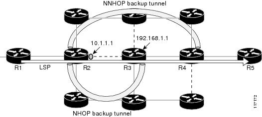
Figure 5 illustrates an NNHOP automatically generated backup tunnel that excludes the router 192.168.1.1 and terminates at router R4. The backup tunnel must avoid touching any links of 192.168.1.1.
Figure 5 Autotunnel Backup for NNHOP
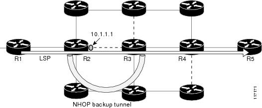
Figure 6 illustrates an NHOP automatically generated backup tunnel that terminates at router R3 and avoids the link 10.1.1.1, not the entire node.
Figure 6 Autotunnel Backup for NHOP
Note
How to Configure MPLS Traffic Engineering: Shared Risk Link Groups
This section contains the following procedures:
•
Configuring the SRLG Membership of Each Link That Has a Shared Risk with Another Link
Enter the commands on the physical interface.
SUMMARY STEPS
1.
2.
3.
4.
5.
DETAILED STEPS
Configuring the Routers That Automatically Create Backup Tunnels to Avoid SRLGs of Their Protected Interfaces
SUMMARY STEPS
1.
2.
3.
4.
DETAILED STEPS
Verifying the MPLS Traffic Engineering: Shared Risk Link Groups Configuration
To verify the MPLS traffic engineering SRLG configuration, perform the following steps.
SUMMARY STEPS
1.
2.
3.
4.
5.
6.
7.
8.
9.
10.
11.
12.
13.
DETAILED STEPS
Step 1
Router> enableRouter# configure terminalRouter(config)# interface pos 3/1Router(config-if)# mpls traffic-eng srlg 1Router(config-if)# mpls traffic-eng srlg 2Router# show running-configinterface POS 3/1ip address 10.0.0.33 255.255.255.255no ip directed-broadcastip router isisencapsulation pppno ip mroute-cachempls traffic-eng tunnelsmpls traffic-eng backup-path Tunnel5000mpls traffic-eng srlg 1mpls traffic-eng srlg 2tag-switching ipcrc 32clock source internalpos ais-shutpos report rdoolpos report laispos report lrdipos report paispos report prdipos report sd-berisis circuit-type level-2-onlyip rsvp bandwidth 20000 20000 sub-pool 5000Step 2
Use this command to show the SRLG membership configured on interface pos 3/1:
Router# show mpls traffic-eng link-management interfaces pos 3/1System Information::Links Count: 11Link ID:: PO3/1 (10.0.0.33)Link Status:SRLGs: 1 2Physical Bandwidth: 2488000 kbits/secMax Res Global BW: 20000 kbits/sec (reserved:0% in, 0% out)Max Res Sub BW: 5000 kbits/sec (reserved:0% in, 0% out)MPLS TE Link State: MPLS TE on, RSVP on, admin-up, floodedInbound Admission: allow-allOutbound Admission: allow-if-roomAdmin. Weight: 10 (IGP)IGP Neighbor Count: 1IGP Neighbor: ID 0000.0000.0004.00, IP 10.0.0.34 (Up)Flooding Status for each configured area [1]:IGP Area[1]: isis level-2: floodedStep 3
Use this command to show the SRLG link membership flooded via the IGP:
Router# show mpls traffic-eng topologyMy_System_id:0000.0000.0003.00 (isis level-2)Signalling error holddown:10 sec Global Link Generation 9IGP Id:0000.0000.0003.00, MPLS TE Id:10.0.3.1 Router Node (isislevel-2)link[0]:Point-to-Point, Nbr IGP Id:0000.0000.0004.00,nbr_node_id:2, gen:9frag_id 0, Intf Address:10.0.0.33, Nbr Intf Address:10.0.0.34TE metric:10, IGP metric:10, attribute_flags:0x0SRLGs:1 2physical_bw:2488000 (kbps), max_reservable_bw_global:20000(kbps)max_reservable_bw_sub:5000 (kbps)Global Pool Sub PoolTotal Allocated Reservable ReservableBW (kbps) BW (kbps) BW (kbps)--------------- ----------- ----------bw[0]: 0 20000 5000bw[1]: 0 20000 5000bw[2]: 0 20000 5000bw[3]: 0 20000 5000bw[4]: 0 20000 5000bw[5]: 0 20000 5000Step 4
Use this command to display all the links in the network that are members of a given SRLG:
Router# show mpls traffic-eng topology srlgMPLS TE Id:0000.0000.0003.00 (isis level-2)SRLG:110.0.0.33SRLG:210.0.0.33The following command shows that there are two links in SRLG 1:
Router# show mpls traffic-eng topology srlgMPLS TE Id:0000.0000.0003.00 (isis level-2)SRLG:110.0.0.3310.0.0.49Step 5
Use this command to display brief topology information:
Router# show mpls traffic-eng topology briefMy_System_id:0000.0000.0003.00 (isis level-2)Signalling error holddown:10 sec Global Link Generation 9IGP Id:0000.0000.0003.00, MPLS TE Id:10.0.3.1 Router Node (isislevel-2)link[0]:Point-to-Point, Nbr IGP Id:0000.0000.0004.00,nbr_node_id:2, gen:9frag_id 0, Intf Address:10.0.0.33, Nbr Intf Address:10.0.0.34TE metric:10, IGP metric:10, attribute_flags:0x0SRLGs:1 2Step 6
Use this command to show local link information that MPLS TE link management is currently flooding into the global TE topology:
Router# show mpls traffic-eng link-management advertisementsFlooding Status: readyConfigured Areas: 1IGP Area[1] ID:: isis level-2System Information::Flooding Protocol: ISISHeader Information::IGP System ID: 0000.0000.0003.00MPLS TE Router ID: 10.0.3.1Flooded Links: 2Link ID:: 0Link Subnet Type: Point-to-PointLink IP Address: 10.0.0.49IGP Neighbor: ID 0000.0000.0007.00, IP 10.0.0.50TE metric: 80000IGP metric: 80000SRLGs: NonePhysical Bandwidth: 622000 kbits/secRes. Global BW: 20000 kbits/secRes. Sub BW: 5000 kbits/secDownstream::Global Pool Sub Pool----------- --------------Reservable Bandwidth[0]: 20000 5000 kbits/secReservable Bandwidth[1]: 20000 5000 kbits/secReservable Bandwidth[2]: 20000 5000 kbits/secReservable Bandwidth[3]: 20000 5000 kbits/secReservable Bandwidth[4]: 20000 5000 kbits/secReservable Bandwidth[5]: 20000 5000 kbits/secReservable Bandwidth[6]: 20000 5000 kbits/secReservable Bandwidth[7]: 20000 5000 kbits/secAttribute Flags: 0x00000000Link ID:: 1Link Subnet Type: Point-to-PointLink IP Address: 10.0.0.33IGP Neighbor: ID 0000.0000.0004.00, IP 10.0.0.34TE metric: 10IGP metric: 10SRLGs: 1Physical Bandwidth: 2488000 kbits/secRes. Global BW: 20000 kbits/secRes. Sub BW: 5000 kbits/secDownstream::Global Pool Sub Pool----------- --------------Reservable Bandwidth[0]: 20000 5000 kbits/secReservable Bandwidth[1]: 20000 5000 kbits/secReservable Bandwidth[2]: 20000 5000 kbits/secReservable Bandwidth[3]: 20000 5000 kbits/secReservable Bandwidth[4]: 20000 5000 kbits/secReservable Bandwidth[5]: 20000 5000 kbits/secReservable Bandwidth[6]: 20000 5000 kbits/secReservable Bandwidth[7]: 20000 5000 kbits/secAttribute Flags: 0x00000000Step 7
Use this command to show that the primary tunnel is going over Pos3/1 on R3, on which SLRG 1 is configured:
Router# show ip rsvp fast-reroutePrimary Protect BW BackupTunnel I/F BPS:Type Tunnel:Label State Level Type------- ------- -------- ------------ ----- ----- ----R3-PRP_t0 PO3/1 0:G None None None None NoneStep 8
mpls traffic-eng auto-tunnel backup srlg exclude force
Use the following commands to configure autotunnel backup with srlg force:
Router(config)# mpls traffic-eng auto-tunnel backupRouter(config)# mpls traffic-eng auto-tunnel backup srlg exclude forceStep 9
Use the following command to verify that srlg force is configured with the srlg exclude pos3/1 link in the IP explicit path:
Router# show ip explicit-pathsPATH __dynamic_tunnel65436 (loose source route, path complete,generation 24, status non-configured)1:exclude-address 10.0.0.332:exclude-srlg 10.0.0.33Step 10
Use the following command to show that autotunnel backup is configured but is down because the headend router does not have any other path to signal and it cannot use pos2/1 because it belongs in the same SRLG; that is, SRLG 1.
Router# show mpls traffic-eng tunnels tunnel 65436Name:R3-PRP_t65436 (Tunnel65436) Destination:10.0.4.1Status:Admin:up Oper:down Path:not valid Signalling:Downpath option 1, type explicit __dynamic_tunnel65436Config Parameters:Bandwidth:0 kbps (Global) Priority:7 7 Affinity:0x0/0xFFFFMetric Type:TE (default)AutoRoute: disabled LockDown:disabled Loadshare:0bw-basedauto-bw:disabledShortest Unconstrained Path Info:Path Weight:10 (TE)Explicit Route:10.0.0.34 10.0.4.1History:Tunnel:Time since created:5 minutes, 29 secondsPath Option 1:Last Error:PCALC::No path to destination, 0000.0000.0004.00Step 11
mpls traffic-eng auto-tunnel backup srlg exclude preferred
The following commands configure autotunnel backup with srlg exclude preferred:
Router(config)# mpls traffic-eng auto-tunnel backupRouter(config)# mpls traffic-eng auto-tunnel backup srlg exclude preferredStep 12
The following command shows srlg exclude preferred with two explicit paths. The first path avoids the SRLGs of the protected interface. The second path does not avoid the SRLGs:
Router# show ip explicit-pathsPATH __dynamic_tunnel65436 (loose source route, path complete,generation 30, status non-configured)1:exclude-address 10.0.0.332:exclude-srlg 10.0.0.33PATH __dynamic_tunnel65436_pathopt2 (loose source route, path complete,generation 33, status non-configured)1:exclude-address 10.0.0.33Step 13
The following command shows that the primary tunnel is protected with autotunnel backup using the second path option (see Step 10) that does not avoid the SRLGs.
Router# show ip rsvp fast-reroutePrimary Protect BW BackupTunnel I/F BPS:Type Tunnel:Label State Level Type------- ------- -------- ------------ ----- ----- ----R3-PRP_t0 PO3/1 0:G 0:G Tu65436:0 Ready any-unl nhopRouter# show mpls traffic-eng tunnels tunnel 65436Name:R3-PRP_t65436 (Tunnel65436) Destination:10.0.4.1Status:Admin:up Oper:up Path:valid Signalling:connectedpath option 2, type explicit __dynamic_tunnel65436_pathopt2 (Basisfor Setup, path weight 80020)path option 1, type explicit __dynamic_tunnel65436Config Parameters:Bandwidth:0 kbps (Global) Priority:7 7 Affinity:0x0/0xFFFFMetric Type:TE (default)AutoRoute: disabled LockDown:disabled Loadshare:0bw-basedauto-bw:disabledActive Path Option Parameters:State:explicit path option 2 is activeBandwidthOverride:disabled LockDown:disabled Verbatim:disabledInLabel : -OutLabel :POS2/1, 23RSVP Signalling Info:Src 10.0.3.1, Dst 10.0.4.1, Tun_Id 65436, Tun_Instance 3RSVP Path Info:My Address:10.0.3.1Explicit Route:10.0.0.50 10.0.0.66 10.0.0.113 10.0.4.1Record Route: NONETspec:ave rate=0 kbits, burst=1000 bytes, peak rate=0 kbitsRSVP Resv Info:Record Route: NONEFspec:ave rate=0 kbits, burst=1000 bytes, peak rate=0 kbitsShortest Unconstrained Path Info:Path Weight:10 (TE)Explicit Route:10.0.0.34 10.0.4.1
Configuration Examples for MPLS Traffic Engineering: Shared Risk Link Groups
This section provides the following configuration examples:
•
Configuring the SRLG Membership of Each Link That Has a Shared Risk with Another Link: Example
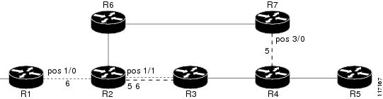
The following example shows how to specify that the SRLG membership of each link has a shared risk with another link.
As shown in Figure 7 and in the following commands:
•
•
•
•
Router1# configure terminalRouter1# interface pos 1/0Router1(config-if)# mpls traffic-eng srlg 6Router2# configure terminalRouter2# interface pos 1/1Router2(config-if)# mpls traffic-eng srlg 5Router2(config-if)# mpls traffic-eng srlg 6Router7# configure terminalRouter7# interface pos 3/0Router7(config-if)# mpls traffic-eng srlg 5Figure 7 SRLG Membership
Configuring the Routers that Automatically Create Backup Tunnels to Avoid SRLGs of Their Protected Interfaces: Example
The following example shows how to specify that automatically created backup tunnels are forced to avoid SRLGs of their protected interface(s):
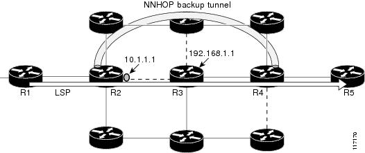
Router# configure terminalRouter(config)# mpls traffic-eng auto-tunnel backupRouter(config)# mpls traffic-eng auto-tunnel backup srlg exclude forceFigure 8 illustrates the automatically created NNHOP backup tunnel that would be created to avoid SRLGs of the protected interface if the following conditions exist:
The exclude-address is 192.168.1.1.
The link at R2 has an IP address of 10.1.1.1.
The backup tunnel's explicit path avoids links that have a membership in the same SRLG as the link whose IP address is 10.1.1.1.
Figure 8 srlg exclude force—NNHOP Autobackup Tunnel
Figure 9 illustrates the automatically created NHOP backup tunnel that would be created.
Figure 9 srlg exclude force—NHOP Autobackup Tunnel
Additional References
The following sections provide references related to the MPLS Traffic Engineering: Shared Risk Link Groups feature.
Related Documents
Standards
MIBs
None
To locate and download MIBs for selected platforms, Cisco IOS releases, and feature sets, use Cisco MIB Locator found at the following URL:
RFCs
Technical Assistance
Command Reference
This feature uses no new or modified commands.
Glossary
Fast Reroute—A mechanism for protecting MPLS traffic engineering (TE) LSPs from link and node failure by locally repairing the LSPs at the point of failure. This protection allows data to continue to flow on them while their headend routers attempt to establish end-to-end LSPs to replace them. FRR locally repairs the protected LSPs by rerouting them over backup tunnels that bypass failed links or nodes.
hop—Passage of a data packet between two network nodes (for example, between two routers).
IGP—Interior Gateway Protocol. An Internet protocol used to exchange routing information within an autonomous system.
interface—A network connection.
IP address—A 32-bit address assigned to hosts using TCP/IP. An IP address belongs to one of five classes (A, B, C, D, or E) and is written as four octets separated by periods (dotted decimal format). Each address consists of a network number, an optional subnetwork number, and a host number. The network and subnetwork numbers together are used for routing, and the host number is used to address an individual host within the network or subnetwork. A subnet mask is used to extract network and subnetwork information from the IP address.
IP explicit path—A list of IP addresses, each representing a node or link in the explicit path.
IS-IS—Intermediate System-to-Intermediate System. OSI link-state hierarchal routing protocol based on DECnet Phase V routing, where intermediate system (IS) routers exchange routing information based on a single metric to determine the network topology.
LDP—Label Distribution Protocol. A standard protocol between MPLS-enabled routers to negotiate the labels (addresses) used to forward packets.
link—A point-to-point connection between adjacent nodes.
LSP—label-switched path. A path that is followed by a labeled packet over several hops, starting at an ingress LSR and ending at an egress LSR.
LSR—label switching router. A Layer 3 router that forwards a packet based on the value of a label encapsulated in the packet.
MPLS—Multiprotocol Label Switching. A method for forwarding packets (frames) through a network. It enables routers at the edge of a network to apply labels to packets. ATM switches or existing routers in the network core can switch packets according to the labels with minimal lookup overhead.
node—An endpoint of a network connection or a junction common to two or more lines in a network. Nodes can be interconnected by links, and serve as control points in the network.
OSPF—Open Shortest Path First. A link-state hierarchical Interior Gateway Protocol (IGP) routing algorithm, derived from the IS-IS protocol. OSPF features include least-cost routing, multipath routing, and load balancing.
router—A network-layer device that uses one or more metrics to determine the optimal path along which network traffic should be forwarded. Routers forward packets from one network to another based on network layer information.
router ID—Something by which a router originating a packet can be uniquely distinguished from all other routers; for example, an IP address from one of the router's interfaces.
traffic engineering—The techniques and processes used to cause routed traffic to travel through the network on a path other than the one that would have been chosen if standard routing methods had been used.
tunnel—A secure communication path between two peers, such as two routers. A traffic engineering tunnel is a label-switched tunnel that is used for traffic engineering. Such a tunnel is set up through means other than normal Layer 3 routing; it is used to direct traffic over a path different from the one that Layer 3 routing could cause the tunnel to take.
Note
CCVP, the Cisco logo, and the Cisco Square Bridge logo are trademarks of Cisco Systems, Inc.; Changing the Way We Work, Live, Play, and Learn is a service mark of Cisco Systems, Inc.; and Access Registrar, Aironet, BPX, Catalyst, CCDA, CCDP, CCIE, CCIP, CCNA, CCNP, CCSP, Cisco, the Cisco Certified Internetwork Expert logo, Cisco IOS, Cisco Press, Cisco Systems, Cisco Systems Capital, the Cisco Systems logo, Cisco Unity, Enterprise/Solver, EtherChannel, EtherFast, EtherSwitch, Fast Step, Follow Me Browsing, FormShare, GigaDrive, HomeLink, Internet Quotient, IOS, iPhone, IP/TV, iQ Expertise, the iQ logo, iQ Net Readiness Scorecard, iQuick Study, LightStream, Linksys, MeetingPlace, MGX, Networking Academy, Network Registrar, Packet, PIX, ProConnect, ScriptShare, SMARTnet, StackWise, The Fastest Way to Increase Your Internet Quotient, and TransPath are registered trademarks of Cisco Systems, Inc. and/or its affiliates in the United States and certain other countries.
All other trademarks mentioned in this document or Website are the property of their respective owners. The use of the word partner does not imply a partnership relationship between Cisco and any other company. (0705R)
Any Internet Protocol (IP) addresses used in this document are not intended to be actual addresses. Any examples, command display output, and figures included in the document are shown for illustrative purposes only. Any use of actual IP addresses in illustrative content is unintentional and coincidental.
© 2004, 2006-2007 Cisco Systems, Inc. All rights reserved.