Feedback Feedback
|
Table Of Contents
MPLS Traffic Engineering and Enhancements
Why Use MPLS Traffic Engineering?
How MPLS Traffic Engineering Works
Enhancement to the SPF Computation
Additional Enhancements to SPF Computation Using Configured Tunnel Metrics
Transitioning an IS-IS Network to a New Technology
New Extensions for the IS-IS Routing Protocol
First Solution for Transitioning an IS-IS Network to a New Technology
Transition Actions During the First Solution
Second Solution for Transitioning an IS-IS Network to a New Technology
Transition Actions During the Second Solution
Implementation in Cisco IOS Software
Related Features and Technologies
Configuring a Device to Support Tunnels
Configuring an Interface to Support RSVP-Based Tunnel Signaling and IGP Flooding
Configuring IS-IS for MPLS Traffic Engineering
Configuring OSPF for MPLS Traffic Engineering
Configuring an MPLS Traffic Engineering Tunnel
Configuring an MPLS Traffic Engineering Tunnel that an IGP Can Use
Configuring MPLS Traffic Engineering Using IS-IS
Configuring MPLS Traffic Engineering Using OSPF
Configuring an MPLS Traffic Engineering Tunnel
Configuring Enhanced SPF Routing Over a Tunnel
debug ip ospf mpls traffic-eng advertisements
debug isis mpls traffic-eng advertisements
debug isis mpls traffic-eng events
debug mpls traffic-eng autoroute
debug mpls traffic-eng link-management admission-control
debug mpls traffic-eng link-management advertisements
debug mpls traffic-eng link-management bandwidth-allocation
debug mpls traffic-eng link-management errors
debug mpls traffic-eng link-management events
debug mpls traffic-eng link-management igp-neighbors
debug mpls traffic-eng link-management links
debug mpls traffic-eng link-management preemption
debug mpls traffic-eng link-management routing
debug mpls traffic-eng load-balancing
debug mpls traffic-eng topology change
debug mpls traffic-eng topology lsa
debug mpls traffic-eng tunnels errors
debug mpls traffic-eng tunnels events
debug mpls traffic-eng tunnels labels
debug mpls traffic-eng tunnels reoptimize
debug mpls traffic-eng tunnels signalling
debug mpls traffic-eng tunnels state
debug mpls traffic-eng tunnels timers
mpls traffic-eng administrative-weight
mpls traffic-eng attribute-flags
mpls traffic-eng flooding thresholds
mpls traffic-eng link-management timers bandwidth-hold
mpls traffic-eng link-management timers periodic-flooding
mpls traffic-eng logging tunnel
mpls traffic-eng reoptimize events
mpls traffic-eng reoptimize timers frequency
mpls traffic-eng signalling advertise implicit-null
mpls traffic-eng tunnels (global configuration)
mpls traffic-eng tunnels (interface configuration)
show ip ospf database opaque-area
show isis mpls traffic-eng adjacency-log
show isis mpls traffic-eng advertisements
show isis mpls traffic-eng tunnel
show mpls traffic-eng autoroute
show mpls traffic-eng link-management admission-control
show mpls traffic-eng link-management advertisements
show mpls traffic-eng link-management bandwidth-allocation
show mpls traffic-eng link-management igp-neighbors
show mpls traffic-eng link-management interfaces
show mpls traffic-eng link-management summary
show mpls traffic-eng topology
show mpls traffic-eng topology path
show mpls traffic-eng tunnels summary
tunnel mpls traffic-eng affinity
tunnel mpls traffic-eng autoroute announce
tunnel mpls traffic-eng autoroute metric
tunnel mpls traffic-eng bandwidth
tunnel mpls traffic-eng path-option
tunnel mpls traffic-eng priority
MPLS Traffic Engineering and Enhancements
First Published: 12.0(5)SLast Updated: February 28, 2006Multiprotocol Label Switching (MPLS) traffic engineering software enables an MPLS backbone to replicate and expand upon the traffic engineering capabilities of Layer 2 ATM and Frame Relay networks. MPLS is an integration of Layer 2 and Layer 3 technologies. By making traditional Layer 2 features available to Layer 3, MPLS enables traffic engineering. Thus, you can offer in a one-tier network what now can be achieved only by overlaying a Layer 3 network on a Layer 2 network.
History for the MPLS Traffic Engineering and Enhancements Feature
Finding Support Information for Platforms and Cisco IOS Software Images
Use Cisco Feature Navigator to find information about platform support and Cisco IOS software image support. Access Cisco Feature Navigator at http://www.cisco.com/go/fn. You must have an account on Cisco.com. If you do not have an account or have forgotten your username or password, click Cancel at the login dialog box and follow the instructions that appear.
Contents
Feature Overview
Traffic engineering is essential for service provider and Internet service provider (ISP) backbones. Such backbones must support a high use of transmission capacity, and the networks must be very resilient so that they can withstand link or node failures.
MPLS traffic engineering provides an integrated approach to traffic engineering. With MPLS, traffic engineering capabilities are integrated into Layer 3, which optimizes the routing of IP traffic, given the constraints imposed by backbone capacity and topology.
MPLS traffic engineering enhances standard Interior Gateway Protocols (IGPs), such as Intermediate System-to-Intermediate System (IS-IS) or Open Shortest Path First (OSPF), to automatically map packets onto the appropriate traffic flows.
•
Transports traffic flows across a network using MPLS forwarding.
•
•
•
•
•
–
–
–
•
Why Use MPLS Traffic Engineering?
WAN connections are an expensive item in an ISP budget. Traffic engineering enables ISPs to route network traffic to offer the best service to their users in terms of throughput and delay. By making the service provider more efficient, traffic engineering reduces the cost of the network.
Currently, some ISPs base their services on an overlay model. In the overlay model, transmission facilities are managed by Layer 2 switching. The routers see only a fully meshed virtual topology, making most destinations appear one hop away. If you use the explicit Layer 2 transit layer, you can precisely control how traffic uses available bandwidth. However, the overlay model has numerous disadvantages. MPLS traffic engineering achieves the traffic engineering benefits of the overlay model without running a separate network, and without needing a nonscalable, full mesh of router interconnects.
How MPLS Traffic Engineering Works
MPLS traffic engineering automatically establishes and maintains LSPs across the backbone by using RSVP. The path that an LSP uses is determined by the LSP resource requirements and network resources, such as bandwidth.
Available resources are flooded by means of extensions to a link-state based IGP.
Traffic engineering tunnels are calculated at the LSP head based on a fit between required and available resources (constraint-based routing). The IGP automatically routes the traffic onto these LSPs. Typically, a packet crossing the MPLS traffic engineering backbone travels on a single LSP that connects the ingress point to the egress point.
MPLS traffic engineering is built on the following Cisco IOS mechanisms:
•
–
–
•
•
•
•
•
•
One approach to engineering a backbone is to define a mesh of tunnels from every ingress device to every egress device. The MPLS traffic engineering path calculation and signaling modules determine the path taken by the LSPs for these tunnels, subject to resource availability and the dynamic state of the network. The IGP, operating at an ingress device, determines which traffic should go to which egress device, and steers that traffic into the tunnel from ingress to egress.
A flow from an ingress device to an egress device might be so large that it cannot fit over a single link, so it cannot be carried by a single tunnel. In this case, multiple tunnels between a given ingress and egress can be configured, and the flow is load-shared among them.
For more information about MPLS (previously referred to as Tag Switching), see the following Cisco documentation:
•
Mapping Traffic into Tunnels
This section describes how traffic is mapped into tunnels; that is, how conventional hop-by-hop link-state routing protocols interact with MPLS traffic engineering capabilities. In particular, this section describes how the shortest path first (SPF) algorithm, sometimes called a Dijkstra algorithm, has been enhanced so that a link-state IGP can automatically forward traffic over tunnels that MPLS traffic engineering establishes.
Link-state protocols, like integrated IS-IS or OSPF, use an SPF algorithm to compute a shortest path tree from the headend node to all nodes in the network. Routing tables are derived from this shortest path tree. The routing tables contain ordered sets of destination and first-hop information. If a router does normal hop-by-hop routing, the first hop is over a physical interface attached to the router.
New traffic engineering algorithms calculate explicit routes to one or more nodes in the network. The originating router views these explicit routes as logical interfaces. In the context of this document, these explicit routes are represented by LSPs and referred to as traffic engineering tunnels (TE tunnels).
The following sections describe how link-state IGPs can use these shortcuts, and how they can install routes in the routing table that point to these TE tunnels. These tunnels use explicit routes, and the path taken by a TE tunnel is controlled by the router that is the headend of the tunnel. In the absence of errors, TE tunnels are guaranteed not to loop, but routers must agree on how to use the TE tunnels. Otherwise, traffic might loop through two or more tunnels.
Enhancement to the SPF Computation
During each step of the SPF computation, a router discovers the path to one node in the network.
•
•
For traffic engineering purposes, each router maintains a list of all TE tunnels that originate at this headend router. For each of those TE tunnels, the router at the tailend is known to the headend router.
During the SPF computation, the TENT (tentative) list stores paths that are possibly the best paths and the PATH list stores paths that are definitely the best paths. When it is determined that a path is the best possible path, the node is moved from TENT to PATH. PATH is thus the set of nodes for which the best path from the computing router has been found. Each PATH entry consists of ID, path cost, and forwarding direction.
The router must determine the first-hop information. There are several ways to do this:
•
•
•
As a result of this computation, traffic to nodes that are the tailend of TE tunnels flows over the TE tunnels. Traffic to nodes that are downstream of the tailend nodes also flows over the TE tunnels. If there is more than one TE tunnel to different intermediate nodes on the path to destination node X, traffic flows over the TE tunnel whose tailend node is closest to node X.
Special Cases and Exceptions
The SPF algorithm finds equal-cost parallel paths to destinations. The enhancement previously described does not change this. Traffic can be forwarded over any of the following:
•
•
•
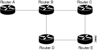
A special situation occurs in the topology shown in Figure 1.
Figure 1
Sample Topology of Parallel Native Paths and Paths over TE Tunnels
If parallel native IP paths and paths over TE tunnels are available, the following implementations allow you to force traffic to flow over TE tunnels only or only over native IP paths. Assume that all links have the same cost and that a TE tunnel is set up from Router A to Router D.
•
•
•
Traffic to Router E now load balances over
•
•
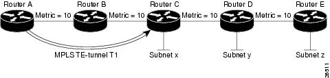
Additional Enhancements to SPF Computation Using Configured Tunnel Metrics
When traffic engineering tunnels install an IGP route in a Router Information Base (RIB) as next hops, the distance or metric of the route must be calculated. Normally, you could make the metric the same as the IGP metric over native IP paths as if the TE tunnels did not exist. For example, Router A can reach Router C with the shortest distance of 20. X is a route advertised in IGP by Router C. Route X is installed in Router A's RIB with the metric of 20. When a TE tunnel from Router A to Router C comes up, by default the route is installed with a metric of 20, but the next-hop information for X is changed.
Although the same metric scheme can work well in other situations, for some applications it is useful to change the TE tunnel metric (for instance, when there are equal cost paths through TE tunnel and native IP links). You can adjust TE tunnel metrics to force the traffic to prefer the TE tunnel, to prefer the native IP paths, or to load share among them.
TE tunnel metrics can force the traffic to prefer some TE tunnels over others, regardless of IGP distances to those destinations.
Setting metrics on TE tunnels does not affect the basic SPF algorithm. It affects only two questions:
1.
2.
You can modify the metrics for determining the first-hop information in one of the following ways:
•
•
•
In each of the above cases, the IGP assigns metrics to routes associated with those tailend routers and their downstream routers.
The SPF computation is loop free because the traffic through the TE tunnels is basically source routed. The end result of TE tunnel metric adjustment is the control of traffic loadsharing. If there is only one way to reach the destination through a single TE tunnel, then no matter what metric is assigned, the traffic has only one way to go.
You can represent the TE tunnel metric in two different ways: (1) as an absolute (or fixed) metric or (2) as a relative (or floating) metric.
If you use an absolute metric, the routes assigned with the metric are fixed. This metric is used not only for the routes sourced on the TE tunnel tailend router, but also for each route downstream of this tailend router that uses this TE tunnel as one of its next hops.
For example, if you have TE tunnels to two core routers in a remote point of presence (POP), and one of them has an absolute metric of 1, all traffic going to that POP traverses this low-metric TE tunnel.
If you use a relative metric, the actual assigned metric value of routes is based on the IGP metric. This relative metric can be positive or negative, and is bounded by minimum and maximum allowed metric values. For example, assume the topology shown in Figure 2.
Figure 2
Topology That Has No Traffic Engineering Tunnel
If there is no TE tunnel, Router A installs routes x, y, and z and assigns metrics 20, 30, and 40 respectively. Suppose that Router A has a TE tunnel T1 to Router C. If the relative metric -5 is used on tunnel T1, the routers x, y, and z have the installed metrics of 15, 25, and 35. If an absolute metric of 5 is used on tunnel T1, routes x, y and z have the same metric 5 installed in the RIB for Router A. The assigning of no metric on the TE tunnel is a special case, a relative metric scheme where the metric is 0.
Transitioning an IS-IS Network to a New Technology
A new flavor of IS-IS includes extensions for MPLS traffic engineering and for other purposes. Running MPLS traffic engineering over IS-IS or taking advantage of these other extensions requires transitioning an IS-IS network to this new technology. This section describes these extensions and discusses two ways to migrate an existing IS-IS network from the standard ISO 10589 protocol towards this new flavor of IS-IS.
Note
New Extensions for the IS-IS Routing Protocol
New extensions for the IS-IS routing protocol serve the following purposes:
•
•
•
To serve these purposes, two new TLVs (type, length, and value objects) have been defined:
•
•
Note
Both new TLVs have a fixed length part, followed by optional sub-TLVs. The metric space in these new TLVs has been enhanced from 6 bits to 24 or 32 bits. The sub-TLVs allow you to add new properties to links and prefixes. Traffic engineering is the first technology to use this ability to add new properties to a link.
The Problem in Theory
Link-state routing protocols compute loop-free routes. This is guaranteed because all routers calculate their routing tables based on the same information from the link-state database (LSPDB).
There is a problem when some routers look at old-style TLVs and some routers look at new-style TLVs because the routers can base their SPF calculations on different information. This can cause routing loops.
The Problem in Practice
The easiest way to migrate from old-style TLVs towards new-style TLVs would be to introduce a "flag day." A flag day means that you reconfigure all routers during a short period of time, during which service is interrupted. If the implementation of a flag day is not acceptable, a network administrator needs to find a viable solution for modern existing networks.
Network administrators have the following problems related to TLVs:
•
•
The new extensions allow a network administrator to use old-style TLVs in one area, and new-style TLVs in another area. However, this is not a solution for administrators who need or want to run their network in one single area. We have a transition scheme that allows both old and new extensions in one area.
The following sections describe two solutions to the network administrator's problems.
First Solution for Transitioning an IS-IS Network to a New Technology
When you migrate from old-style TLVs towards new-style TLVs, you can advertise the same information twice—once in old-style TLVs and once in new-style TLVs. This ensures that all routers can understand what is advertised.
There are three disadvantages to using that approach:
•
–
–
•
–
–
•
These problems can be largely solved easily by using
•
•
The main benefit to advertising the same information twice is that network administrators can use new-style TLVs before all routers in the network can understand them.
Transition Actions During the First Solution
When transitioning from using IS-IS with old-style TLVs to new-style TLVs, you can perform the following actions:
•
•
•
•
•
•
•
For more information about how to perform these actions, see "TLV Configuration Commands" section.
Second Solution for Transitioning an IS-IS Network to a New Technology
Routers advertise only one style of TLVs at the same time, but can understand both types of TLVs during migration. There are two main benefits to this approach:
•
•
This method is useful when you are transitioning the whole network (or a whole area) to use wider metrics (that is, you want a router running IS-IS to generate and accept only new-style TLVs). For more information, see the metric-style wide command.
The disadvantage is that all routers must understand the new-style TLVs before any router can start advertising new-style TLVs. It does not help the second problem, where network administrators want to use the new-style TLVs for traffic engineering, while some routers are capable of understanding only old-style TLVs.
Transition Actions During the Second Solution
If you use the second solution, you can perform the following actions:
•
•
•
•
•
•
TLV Configuration Commands
Cisco IOS has a new router isis command line interface (CLI) subcommand called metric-style. Once you are in the router IS-IS subcommand mode, you have the option to choose the following:
•
•
•
For more information about the commands, see the "Command Reference" section in this document.
You can use either of two transition schemes when you are using the metric-style commands:
•
•
Implementation in Cisco IOS Software
Cisco IOS software implements both transition solutions. Network administrators can choose the solution that suits them best. For test networks, the first solution is ideal (go to "First Solution for Transitioning an IS-IS Network to a New Technology" section). For a real transition, both solutions can be used. The first solution requires fewer steps and less configuration. Only the largest networks that do not want to risk doubling their LSPDB during transition need to use the second solution (go to "Second Solution for Transitioning an IS-IS Network to a New Technology" section).
Benefits
MPLS traffic engineering has the following benefits:
•
•
Restrictions
The following restrictions apply to MPLS traffic engineering:
•
•
•
Related Features and Technologies
The MPLS traffic engineering feature is related to the IS-IS, OSPF, RSVP, and MPLS features (formerly referred to as tag switching). These features are presented in Cisco product documentation (see the "Related Documents" section and "How MPLS Traffic Engineering Works" section).
Prerequisites
Your network must support the following Cisco IOS features before you enable MPLS traffic engineering:
•
•
•
Configuration Tasks
Perform the following tasks before you enable MPLS traffic engineering:
•
•
•
Perform the following tasks to configure MPLS traffic engineering:
•
•
•
•
•
•
Configuring a Device to Support Tunnels
To configure a device to support tunnels, perform the following steps in configuration mode.
Configuring an Interface to Support RSVP-Based Tunnel Signaling and IGP Flooding
To configure an interface to support RSVP-based tunnel signaling and IGP flooding, perform these steps in interface configuration mode:
Note
Configuring IS-IS for MPLS Traffic Engineering
To configure IS-IS for MPLS traffic engineering, perform the steps described below. For a description of the IS-IS commands (excluding the IS-IS traffic engineering commands), see the Cisco IOS IP Command Reference, Volume 2 of 3: Routing Protocols, Release 12.2
Configuring OSPF for MPLS Traffic Engineering
To configure OSPF for MPLS traffic engineering, perform the steps described below. For a description of the OSPF commands (excluding the OSPF traffic engineering commands), see the Cisco IOS IP Command Reference, Volume 2 of 3: Routing Protocols, Release 12.2.
Configuring an MPLS Traffic Engineering Tunnel
To configure an MPLS traffic engineering tunnel, perform these steps in interface configuration mode. This tunnel has two path setup options: a preferred explicit path and a backup dynamic path.
Configuring an MPLS Traffic Engineering Tunnel that an IGP Can Use
To configure an MPLS traffic engineering tunnel that an IGP can use, perform these steps in interface configuration mode. This tunnel has two path setup options: a preferred explicit path and a backup dynamic path.
Configuration Examples
This section provides the following configuration examples:
•
•
•
•
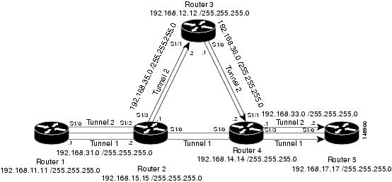
Figure 3 illustrates a sample MPLS topology. This example specifies point-to-point outgoing interfaces. The next sections contain sample configuration commands you enter to implement MPLS traffic engineering and the basic tunnel configuration shown in Figure 3.
Figure 3 Sample MPLS Traffic Engineering Tunnel Configuration
Configuring MPLS Traffic Engineering Using IS-IS
This example lists the commands you enter to configure MPLS traffic engineering with IS-IS routing enabled (see Figure 3).
Note
Router 1—MPLS Traffic Engineering Configuration
To configure MPLS traffic engineering, enter the following commands:
ip cefmpls traffic-eng tunnelsinterface loopback 0ip address 192.168.11.11 255.255.255.0ip router isisinterface s1/0ip address 192.168.31.0 255.255.255.0.0ip router isismpls traffic-eng tunnelsip rsvp bandwidth 1000Router 1—IS-IS Configuration
To enable IS-IS routing, enter the following commands:
router isisnetwork 47.0000.0011.0011.00is-type level-1metric-style widempls traffic-eng router-id loopback0mpls traffic-eng level-1Configuring MPLS Traffic Engineering Using OSPF
This example lists the commands you enter to configure MPLS traffic engineering with OSPF routing enabled (see Figure 3).
Note
Router 1—MPLS Traffic Engineering Configuration
To configure MPLS traffic engineering, enter the following commands:
ip cefmpls traffic-eng tunnelsinterface loopback 0ip address 192.168.11.11 255.255.255.0interface s1/0ip address 192.168.31.0 255.255.255.0.0mpls traffic-eng tunnelsip rsvp bandwidth 1000Router 1—OSPF Configuration
To enable OSPF, enter the following commands:
router ospf 0network 192.168.31.0 255.255.255 area 0mpls traffic-eng router-id Loopback0mpls traffic-eng area 0Configuring an MPLS Traffic Engineering Tunnel
This example shows you how to configure a dynamic path tunnel and an explicit path in the tunnel. Before you configure MPLS traffic engineering tunnels, you must enter the appropriate global and interface commands on the specified router (in this case, Router 1).
Router 1—Dynamic Path Tunnel Configuration
In this section, a tunnel is configured to use a dynamic path.
interface tunnel1ip unnumbered loopback 0tunnel destination 192.168.17.17 255.255.255.0tunnel mode mpls traffic-engtunnel mpls traffic-eng bandwidth 100tunnel mpls traffic-eng priority 1 1tunnel mpls traffic-eng path-option 1 dynamicRouter 1—Dynamic Path Tunnel Verification
This section includes the commands you use to verify that the tunnel is up.
show mpls traffic-eng tunnelsshow ip interface tunnel1Router 1—Explicit Path Configuration
In this section, an explicit path is configured.
ip explicit-path identifier 1next-address 192.168.131.0 255.255.255.0next-address 192.168.135.0 255.255.255.0next-address 192.168.136.0 255.255.255.0next-address 192.168.133.0 255.255.255.0Router 1—Explicit Path Tunnel Configuration
In this section, a tunnel is configured to use an explicit path.
interface tunnel2ip unnumbered loopback 0tunnel destination 192.168.17.17 255.255.255.0tunnel mode mpls traffic-engtunnel mpls traffic-eng bandwidth 100tunnel mpls traffic-eng priority 1 1tunnel mpls traffic-eng path-option 1 explicit identifier 1Router 1—Explicit Path Tunnel Verification
This section includes the commands you use to verify that the tunnel is up.
show mpls traffic-eng tunnelsshow ip interface tunnel2Configuring Enhanced SPF Routing Over a Tunnel
This section includes the commands that cause the tunnel to be considered by the IGP's enhanced SPF calculation, which installs routes over the tunnel for appropriate network prefixes.
Router 1—IGP Enhanced SPF Consideration Configuration
In this section, you specify that the IGP should use the tunnel (if the tunnel is up) in its enhanced shortest path first (SPF) calculation.
interface tunnel1tunnel mpls traffic-eng autoroute announceRouter 1—Route and Traffic Verification
This section includes the commands you use to verify that the tunnel is up and that the traffic is routed through the tunnel.
show traffic-eng tunnels tunnel1 briefshow ip route 192.168.17.17 255.255.255.0show mpls traffic-eng autorouteping 192.168.17.17 255.255.255.0show interface tunnel1 accountingshow interface s1/0 accountingAdditional References
The following sections provide references related to MPLS Traffic Engineering and Enhancements.
Related Documents
IP routing protocols
"IP Routing Protocols" chapter in the Cisco IOS Switching Services Configuration Guide, Release 12.2
Multiprotocol Label Switching
"Multiprotocol Label Switching" chapter in the Cisco IOS Switching Services Configuration Guide, Release 12.2.
Standards
MIBs
None
To locate and download MIBs for selected platforms, Cisco IOS releases, and feature sets, use Cisco MIB Locator found at the following URL:
RFCs
Technical Assistance
Command Reference
This section documents modified commands only.
•
•
•
•
•
•
•
•
•
•
•
•
•
•
•
•
•
•
•
•
•
•
•
•
•
•
•
•
•
•
•
•
•
•
•
•
•
•
•
•
•
•
•
•
•
•
•
•
•
•
•
•
•
•
•
•
•
append-after
To insert a path entry after a specified index number, use the append-after command in IP explicit path configuration mode.
append-after index command
Syntax Description
Defaults
No path entry is inserted after a specified index number.
Command Modes
IP explicit path configuration
Command History
Examples
In the following example, the next-address command is inserted after index 5:
Router(config-ip-expl-path)# append-after 5 next-address 10.3.27.3Related Commands
debug ip ospf mpls traffic-eng advertisements
To print information about traffic engineering advertisements in Open Shortest Path First (OSPF) link state advertisement (LSA) messages, use the debug ip ospf mpls traffic-eng advertisements command in privileged EXEC mode. To disable debugging output, use the no form of this command.
debug ip ospf mpls traffic-eng advertisements
no debug ip ospf mpls traffic-eng advertisements
Syntax Description
This command has no arguments or keywords
Defaults
No default behavior or values
Command Modes
Privileged EXEC
Command History
Examples
In the following example, information about traffic engineering advertisements is printed in OSPF LSA messages:
Router# debug ip ospf mpls traffic-eng advertisementsOSPF:IGP delete router node 10.106.0.6 fragment 0 with 0 linksTE Router ID 10.106.0.6OSPF:IGP update router node 10.110.0.10 fragment 0 with 0 linksTE Router ID 10.110.0.10OSPF:MPLS announce router node 10.106.0.6 fragment 0 with 1 linksLink connected to Point-to-Point networkLink ID :10.110.0.10Interface Address :10.1.0.6Neighbor Address :10.1.0.10Admin Metric :10Maximum bandwidth :1250000Maximum reservable bandwidth :625000Number of Priority :8Priority 0 :625000 Priority 1 :625000Priority 2 :625000 Priority 3 :625000Priority 4 :625000 Priority 5 :625000Priority 6 :625000 Priority 7 :625000Affinity Bit :0x0Table 1 describes the significant fields shown in the display.
debug isis mpls traffic-eng advertisements
To print information about traffic engineering advertisements in Intermediate System-to-Intermediate System (IS-IS) link-state advertisement (LSA) messages, use the debug isis mpls traffic-eng advertisements command in privileged EXEC mode. To disable debugging output, use the no form of this command.
debug isis mpls traffic-eng advertisements
no debug isis mpls traffic-eng advertisements
Syntax Description
This command has no arguments or keywords.
Defaults
No default behavior or values
Command Modes
Privileged EXEC
Command History
Examples
In the following example, information about traffic engineering advertisements is printed in IS-IS LSA messages:
Router# debug isis mpls traffic-eng advertisementsSystem ID:Router1.00Router ID:10.106.0.6Link Count:1Link[1]Neighbor System ID:Router2.00 (P2P link)Interface IP address:10.42.0.6Neighbor IP Address:10.42.0.10Admin. Weight:10Physical BW:155520000 bits/secReservable BW:5000000 bits/secBW unreserved[0]:2000000 bits/sec, BW unreserved[1]:100000 bits/secBW unreserved[2]:100000 bits/sec, BW unreserved[3]:100000 bits/secBW unreserved[4]:100000 bits/sec, BW unreserved[5]:100000 bits/secBW unreserved[6]:100000 bits/sec, BW unreserved[7]:0 bits/secAffinity Bits:0x00000000Table 2 describes the significant fields shown in the display.
debug isis mpls traffic-eng events
To print information about traffic engineering-related Intermediate System-to-Intermediate System (IS-IS) events, use the debug isis mpls traffic-eng events command in privileged EXEC mode. To disable debugging output, use the no form of this command.
debug isis mpls traffic-eng events
no debug isis mpls traffic-eng events
Syntax Description
This command has no arguments or keywords.
Defaults
No default behavior or values
Command Modes
Privileged EXEC
Command History
Examples
In the following example, information is printed about traffic engineering-related IS-IS events:
Router# debug isis mpls traffic-eng eventsISIS-RRR:Send MPLS TE Et4/0/1 Router1.02 adjacency down:address 0.0.0.0ISIS-RRR:Found interface address 10.1.0.6 Router1.02, building subtlv... 58 bytesISIS-RRR:Found interface address 10.42.0.6 Router2.00, building subtlv... 64 bytesISIS-RRR:Interface address 0.0.0.0 Router1.00 not found, not building subtlvISIS-RRR:LSP Router1.02 changed from 0x606BCD30ISIS-RRR:Mark LSP Router1.02 changed because TLV contents different, code 16ISIS-RRR:Received 1 MPLS TE links flood info for system id Router1.00debug mpls traffic-eng areas
To print information about traffic engineering area configuration change events, use the debug mpls traffic-eng areas command in privileged EXEC mode. To disable debugging output, use the no form of this command.
debug mpls traffic-eng areas
no debug mpls traffic-eng areas
Syntax Description
This command has no arguments or keywords.
Defaults
No default behavior or values
Command Modes
Privileged EXEC
Command History
Examples
In the following example, information is printed about traffic engineering area configuration change events:
Router# debug mpls traffic-eng areasTE-AREAS:isis level-1:up eventTE-PCALC_LSA:isis level-1debug mpls traffic-eng autoroute
To print information about automatic routing over traffic engineering tunnels, use the debug mpls traffic-eng autoroute command in privileged EXEC mode. To disable debugging output, use the no form of this command.
debug mpls traffic-eng autoroute
no debug mpls traffic-eng autoroute
Syntax Description
This command has no arguments or keywords.
Defaults
No default behavior or values
Command Modes
Privileged EXEC
Command History
Examples
In the following example, information is printed about automatic routing over traffic engineering tunnels:
Router# debug mpls traffic-eng autorouteTE-Auto:announcement that destination 0001.0000.0003.00 has 1 tunnelsTunnel1 (traffic share 333, nexthop 10.112.0.12)debug mpls traffic-eng link-management admission-control
To print information about traffic engineering label-switched path (LSP) admission control on traffic engineering interfaces, use the debug mpls traffic-eng link-management admission-control command in privileged EXEC mode. To disable debugging output, use the no form of this command.
debug mpls traffic-eng link-management admission-control [detail] [acl-number]
no debug mpls traffic-eng link-management admission-control [detail]
Syntax Description
Defaults
No default behavior or values
Command Modes
Privileged EXEC
Command History
Examples
In the following example, information is printed about traffic engineering LSP admission control on traffic engineering interfaces:
Router# debug mpls traffic-eng link-management admission-controlTE-LM-ADMIT:tunnel 10.106.0.6 1_10002:created [total 4]TE-LM-ADMIT:tunnel 10.106.0.6 1_10002: "None" -> "New"TE-LM-ADMIT:tunnel 10.106.0.6 1_10002: "New" -> "Admitting 2nd Path Leg"TE-LM-ADMIT:tunnel 10.106.0.6 1_10002: "Admitting 2nd Path Leg" -> "Path Admitted"TE-LM-ADMIT:Admission control has granted Path query for 10.106.0.6 1_10002 (10.112.0.12) on link Ethernet4/0/1 [reason 0]TE-LM-ADMIT:tunnel 10.106.0.6 1_10002: "Path Admitted" -> "Admitting 1st Resv Leg"TE-LM-ADMIT:tunnel 10.106.0.6 1_10002: "Admitting 1st Resv Leg" -> "Resv Admitted"TE-LM-ADMIT:Admission control has granted Resv query for 10.106.0.6 1_10002 (10.112.0.12) on link Ethernet4/0/1 [reason 0]debug mpls traffic-eng link-management advertisements
To print information about resource advertisements for traffic engineering interfaces, use the debug mpls traffic-eng link-management advertisements command in privileged EXEC mode. To disable debugging output, use the no form of this command.
debug mpls traffic-eng link-management advertisements [detail] [acl-number]
no debug mpls traffic-eng link-management advertisements [detail] [acl-number]
Syntax Description
detail
(Optional) Prints detailed debugging information.
acl-number
(Optional) Uses the specified access list to filter the debugging information.
Defaults
No default behavior or values
Command Modes
Privileged EXEC
Command History
Examples
In the following example, detailed debugging information is printed about resource advertisements for traffic engineering interfaces:
Router# debug mpls traffic-eng link-management advertisements detailTE-LM-ADV:area isis level-1:IGP announcement:link Et4/0/1:info changedTE-LM-ADV:area isis level-1:IGP msg:link Et4/0/1:includes subnet type (2), described nbrs (1)TE-LM-ADV:area isis level-1:IGP announcement:link Et4/0/1:info changedTE-LM-ADV:area isis level-1:IGP msg:link Et4/0/1:includes subnet type (2), described nbrs (1)TE-LM-ADV:LSA:Flooding manager received message:link information change (Et4/0/1)TE-LM-ADV:area isis level-1:*** Flooding node information ***System Information::Flooding Protocol: ISISHeader Information::IGP System ID: 0001.0000.0001.00MPLS TE Router ID: 10.106.0.6Flooded Links: 1Link ID:: 0Link IP Address: 10.1.0.6IGP Neighbor: ID 0001.0000.0001.02Admin. Weight: 10Physical Bandwidth: 10000 kbits/secMax Reservable BW: 5000 kbits/secDownstream::Reservable Bandwidth[0]: 5000 kbits/secReservable Bandwidth[1]: 2000 kbits/secReservable Bandwidth[2]: 2000 kbits/secReservable Bandwidth[3]: 2000 kbits/secReservable Bandwidth[4]: 2000 kbits/secReservable Bandwidth[5]: 2000 kbits/secReservable Bandwidth[6]: 2000 kbits/secAttribute Flags: 0x00000000Table 3 describes the significant fields shown in the display.
debug mpls traffic-eng link-management bandwidth-allocation
To print detailed information about bandwidth allocation for traffic engineering label-switched paths (LSPs), use the debug mpls traffic-eng link-management bandwidth-allocation command in privileged EXEC mode. To disable debugging output, use the no form of this command.
debug mpls traffic-eng link-management bandwidth-allocation [detail] [acl-number]
no debug mpls traffic-eng link-management bandwidth-allocation [detail] [acl-number]
Syntax Description
Defaults
No default behavior or values
Command Modes
Privileged EXEC
Command History
Examples
In the following example, information is printed about bandwidth allocation for traffic engineering LSPs:
Router# debug mpls traffic-eng link-management bandwidth-allocationTE-LM-BW:tunnel 10.106.0.6 1_10002:requesting Downstream bw hold (3000000 bps [S]) on link Et4/0/1TE-LM-BW:tunnel 10.106.0.6 1_10002:Downstream bw hold request succeededTE-LM-BW:tunnel 10.106.0.6 1_10002:requesting Downstream bw lock (3000000 bps [S]) on link Et4/0/1TE-LM-BW:tunnel 10.106.0.6 1_10002:Downstream bw lock request succeeded×_„RsRelated Commands
debug mpls traffic-eng link-management errors
To print information about errors encountered during any traffic engineering link management procedure, use the debug mpls traffic-eng link-management errors command in privileged EXEC mode. To disable debugging output, use the no form of this command.
debug mpls traffic-eng link-management errors [detail]
no debug mpls traffic-eng link-management errors [detail]
Syntax Description
Defaults
No default behavior or values
Command Modes
Privileged EXEC
Command History
Examples
In the following example, detailed debugging information is printed about errors encountered during a traffic engineering link management procedure:
Router# debug mpls traffic-eng link-management errors detail00:04:48 TE-LM-ROUTING: link Et1/1/1: neighbor 0010.0000.0012.01: add to IP peer db failedRelated Commands
debug mpls traffic-eng link-management events
To print information about traffic engineering link management system events, use the debug mpls traffic-eng link-management events command in privileged EXEC mode. To disable debugging output, use the no form of this command.
debug mpls traffic-eng link-management events [detail]
no debug mpls traffic-eng link-management events [detail]
Syntax Description
Defaults
No default behavior or values
Command Modes
Privileged EXEC
Command History
Examples
In the following example, detailed debugging information is printed about traffic engineering link management system events:
Router# debug mpls traffic-eng link-management events detailTE-LM-EVENTS:stopping MPLS TE Link Management processTE-LM-EVENTS:MPLS TE Link Management process dying nowdebug mpls traffic-eng link-management igp-neighbors
To print information about changes to the link management database of Interior Gateway Protocol (IGP) neighbors, use the debug mpls traffic eng link-management igp-neighbors command in privileged EXEC mode. To disable debugging output, use the no form of this command.
debug mpls traffic-eng link-management igp-neighbors [detail]
no debug mpls traffic-eng link-management igp-neighbors [detail]
Syntax Description
Defaults
No default behavior or values
Command Modes
Privileged EXEC
Command History
Examples
In the following example, detailed debugging information is printed about changes to the link management database of IGP neighbors:
Router# debug mpls traffic-eng link-management igp-neighbors detailTE-LM-NBR:link AT0/0.2:neighbor 0001.0000.0002.00:created (isis level-1, 10.42.0.10, Up)[total 2]Related Commands
debug mpls traffic-eng link-management events
Prints information about traffic engineering-related ISIS events.
debug mpls traffic-eng link-management links
To print information about traffic engineering link management interface events, use the debug mpls traffic-eng link-management links command in privileged EXEC mode. To disable debugging output, use the no form of this command.
debug mpls traffic-eng link-management links [detail]
no debug mpls traffic-eng link-management links [detail]
Syntax Description
Defaults
No default behavior or values
Command Modes
Privileged EXEC
Command History
Examples
In the following example, detailed debugging information is printed about traffic engineering link management interface events:
Router# debug mpls traffic-eng link-management links detailTE-LM-LINKS:link AT0/0.2:RSVP enabledTE-LM-LINKS:link AT0/0.2:increasing RSVP bandwidth from 0 to 5000000TE-LM-LINKS:link AT0/0.2:created [total 2]TE-LM-LINKS:Binding MPLS TE LM Admission Control as the RSVP Policy Server on ATM0/0.2TE-LM-LINKS:Bind attempt succeededTE-LM-LINKS:link AT0/0.2:LSP tunnels enableddebug mpls traffic-eng link-management preemption
To print information about traffic engineering label-switched path (LSP) preemption, use the debug mpls traffic-eng link-management preemption command in privileged EXEC mode. To disable debugging output, use the no form of this command.
debug mpls traffic-eng link-management preemption [detail]
no debug mpls traffic-eng link-management preemption [detail]
Syntax Description
Defaults
No default behavior or values
Command Modes
Privileged EXEC
Command History
12.1(3)T
This command was introduced.
12.2(28)SB
This command was integrated into Cisco IOS Release 12.2(28)SB.
Examples
In the following example, detailed debugging information is printed about traffic engineering LSP preemption:
Router# debug mpls traffic-eng link-management preemption detailTE-LM-BW:preempting Downstream bandwidth, 1000000, for tunnel 10.106.0.6 2_2TE-LM-BW:building preemption list to get bandwidth, 1000000, for tunnel 10.106.0.6 2_2 (priority 0)TE-LM-BW:added bandwidth, 3000000, from tunnel 10.106.0.6 1_2 (pri 1) to preemption listTE-LM-BW:preemption list build to get bw, 1000000, succeeded (3000000)TE-LM-BW:preempting bandwidth, 1000000, using plist with 1 tunnelsTE-LM-BW:tunnel 10.106.0.6 1_2:being preempted on AT0/0.2 by 10.106.0.6 2_2TE-LM-BW:preemption of Downstream bandwidth, 1000000, succeededdebug mpls traffic-eng link-management routing
To print information about traffic engineering link management routing resolutions that can be performed to help Resource Reservation Protocol (RSVP) interpret explicit route objects, use the debug mpls traffic-eng link-management routing command in privileged EXEC mode. To disable debugging output, use the no form of this command.
debug mpls traffic-eng link-management routing [detail]
no debug mpls traffic-eng link-management routing [detail]
Syntax Description
Defaults
No default behavior or values
Command Modes
Privileged EXEC
Command History
Examples
In the following example, detailed debugging information is printed about traffic engineering link management routing resolutions that can be performed to help RSVP interpret explicit route objects:
Router# debug mpls traffic-eng link-management routing detailTE-LM-ROUTING:route options to 10.42.0.10:building list (w/ nhop matching)TE-LM-ROUTING:route options to 10.42.0.10:adding {AT0/0.2, 10.42.0.10}TE-LM-ROUTING:route options to 10.42.0.10:completed list has 1 linksRelated Commands
debug mpls traffic-eng load-balancing
To print information about unequal cost load balancing over traffic engineering tunnels, use the debug mpls traffic-eng load-balancing command in privileged EXEC mode. To disable debugging output, use the no form of this command.
debug mpls traffic-eng load-balancing
no debug mpls traffic-eng load-balancing
Syntax Description
This command has no arguments or keywords.
Defaults
No default behavior or values
Command Modes
Privileged EXEC
Command History
Examples
In the following example, information is printed about unequal cost load balancing over traffic engineering tunnels:
Router# debug mpls traffic-eng load-balancingTE-Load:10.210.0.0/16, 2 routes, loadbalancing based on MPLS TE bandwidthTE-Load:10.200.0.0/16, 2 routes, loadbalancing based on MPLS TE bandwidthdebug mpls traffic-eng path
To print information about traffic engineering path calculation, use the debug mpls traffic-eng path command in privileged EXEC mode. To disable debugging output, use the no form of this command.
debug mpls traffic-eng path {num | lookup | spf | verify}
no debug mpls traffic-eng path {num | lookup | spf | verify}
Syntax Description
Defaults
No default behavior or values
Command Modes
Privileged EXEC
Command History
Examples
In the following example, information is printed about the calculation of the traffic engineering path:
Router# debug mpls traffic-eng path lookupTE-PCALC:Tunnel1000 Path Setup to 10.110.0.10:FULL_PATHTE-PCALC:bw 0, min_bw 0, metric:0TE-PCALC:setup_pri 0, hold_pri 0TE-PCALC:affinity_bits 0x0, affinity_mask 0xFFFFTE-PCALC_PATH:create_path_hoplist:ip addr 10.42.0.6 unknown.debug mpls traffic-eng topology change
To print information about traffic engineering topology change events, use the debug mpls traffic-eng topology change command in privileged EXEC mode. To disable debugging output, use the no form of this command.
debug mpls traffic-eng topology change
no debug mpls traffic-eng topology change
Syntax Description
This command has no arguments or keywords.
Defaults
No default behavior or values
Command Modes
Privileged EXEC
Command History
Examples
In the following example, information is printed about traffic engineering topology change events:
Router# debug mpls traffic-eng topology changeTE-PCALC_LSA:NODE_CHANGE_UPDATE isis level-1link flags:LINK_CHANGE_BWsystem_id:0001.0000.0001.00, my_ip_address:10.42.0.6nbr_system_id:0001.0000.0002.00, nbr_ip_address 10.42.0.10debug mpls traffic-eng topology lsa
To print information about traffic engineering topology link state advertisement (LSA) events, use the debug mpls traffic-eng topology lsa command in privileged EXEC mode. To disable debugging output, use the no form of this command.
debug mpls traffic-eng topology lsa
no debug mpls traffic-eng topology lsa
Syntax Description
This command has no arguments or keywords.
Defaults
No default behavior or values
Command Modes
Privileged EXEC
Command History
Examples
In the following example, information is printed about traffic engineering topology LSA events:
Router# debug mpls traffic-eng topology lsaTE-PCALC_LSA:node_lsa_add:Received a LSA:flags 0x1 !IGP Id:0001.0000.0001.00, MPLS TE Id:10.106.0.6 is VALID has 2 links (frag_id 0)link[0 ]:Nbr IGP Id:0001.0000.0001.02frag_id 0, Intf Address:0.0.0.0admin_weight:10, attribute_flags:0x0link[1 ]:Nbr IGP Id:0001.0000.0002.00frag_id 0, Intf Address:10.42.0.6, Nbr Intf Address:10.42.0.10admin_weight:100, attribute_flags:0x0TE-PCALC_LSA:(isis level-1):Received lsa:IGP Id:0001.0000.0001.00, MPLS TE Id:10.106.0.6 Router Node id 8link[0 ]:Nbr IGP Id:0001.0000.0002.00, nbr_node_id:9, gen:114frag_id 0, Intf Address:10.42.0.6, Nbr Intf Address:10.42.0.10admin_weight:100, attribute_flags:0x0physical_bw:155520 (kbps), max_reservable_bw:5000 (kbps)allocated_bw reservable_bw allocated_bw reservable_bw------------ ------------- ------------ -------------bw[0]:0 5000 bw[1]:3000 2000bw[2]:0 2000 bw[3]:0 2000bw[4]:0 2000 bw[5]:0 2000bw[6]:0 2000 bw[7]:0 2000debug mpls traffic-eng tunnels errors
To print information about errors encountered during any traffic engineering tunnel management procedure, use the debug mpls traffic-eng tunnels errors command in privileged EXEC mode. To disable debugging output, use the no form of this command.
debug mpls traffic-eng tunnels errors [detail]
no debug mpls traffic-eng tunnels errors [detail]
Syntax Description
Defaults
No default behavior or values
Command Modes
Privileged EXEC
Command History
Examples
In the following example, detailed debugging information is printed about errors encountered during a traffic engineering tunnel management procedure:
Router# debug mpls traffic-eng tunnels errors00:04:14: LSP-TUNNEL-SIG: Tunnel10012[1]: path verification failed (unprotected) [Can't use link 10.12.4.4 on node 10.0.0.4]debug mpls traffic-eng tunnels events
To print information about traffic engineering tunnel management system events, use the debug mpls traffic-eng tunnels events command in privileged EXEC mode. To disable debugging output, use the no form of this command.
debug mpls traffic-eng tunnels events [detail]
no debug mpls traffic-eng tunnels events [detail]
Syntax Description
Defaults
No default behavior or values
Command Modes
Privileged EXEC
Command History
Examples
In the following example, detailed debugging information is printed about traffic engineering tunnel management system events:
Router# debug mpls traffic-eng tunnels events detailLSP-TUNNEL:received event:interface admin. down [Ethernet4/0/1]LSP-TUNNEL:posting action(s) to all-tunnels:check static LSPsLSP-TUNNEL:scheduling pending actions on all-tunnelsLSP-TUNNEL:applying actions to all-tunnels, as follows:check static LSPsdebug mpls traffic-eng tunnels labels
To print information about Multiprotocol Label Switching (MPLS) label management for traffic engineering tunnels, use the debug mpls traffic-eng tunnels labels command in privileged EXEC mode. To disable debugging output, use the no form of this command.
debug mpls traffic-eng tunnels labels [detail] [acl-number]
no debug mpls traffic-eng tunnels labels [detail] [acl-number]
Syntax Description
Defaults
No default behavior or values
Command Modes
Privileged EXEC
Command History
Examples
In the following example, detailed debugging information is printed about MPLS label management for traffic engineering tunnels:
Router# debug mpls traffic-eng tunnels labels detailLSP-TUNNEL-LABELS:tunnel 10.106.0.6 1 [2]:fabric PROGRAM requestLSP-TUNNEL-LABELS:tunnel 10.106.0.6 1 [2]:programming label 16 on output interface ATM0/0.2LSP-TUNNEL-LABELS:descriptor 71FA64:continuing "Program" requestLSP-TUNNEL-LABELS:descriptor 71FA64:set "Interface Point Out State" to, allocatedLSP-TUNNEL-LABELS:# of resource points held for "default" interfaces:2LSP-TUNNEL-LABELS:descriptor 71FA64:set "Fabric State" to, enabledLSP-TUNNEL-LABELS:descriptor 71FA64:set "Fabric Kind" to, default (LFIB)LSP-TUNNEL-LABELS:descriptor 71FA64:set "Fabric State" to, setLSP-TUNNEL-LABELS:tunnel 10.106.0.6 1 [2]:fabric PROGRAM replyTo restrict output to information about a single tunnel, you can configure an access list and supply it to the debug command. Configure the access list as follows:
Router(config-ext-nacl)# permit udp host scr_address host dst_address eq tun intfcFor example, if tunnel 10012 has destination 10.0.0.11 and source 10.0.0.4, as determined by the show mpls traffic-eng tunnels command, the following access list could be configured and added to the debug command:
Router(config-ext-nacl)# permit udp host 10.0.0.4 10.0.0.11 eq 10012debug mpls traffic-eng tunnels reoptimize
To print information about traffic engineering tunnel reoptimizations, use the debug mpls traffic-eng tunnels reoptimize command in privileged EXEC mode. To disable debugging output, use the no form of this command.
debug mpls traffic-eng tunnels reoptimize [detail] [acl-number]
no debug mpls traffic-eng tunnels reoptimize [detail] [acl-number]
Syntax Description
Defaults
No default behavior or values
Command Modes
Privileged EXEC
Command History
Examples
In the following example, detailed debugging information is printed about traffic engineering tunnel reoptimizations that match access list number 101:
Router# debug mpls traffic-eng tunnels reoptimize detail 101LSP-TUNNEL-REOPT:Tunnel1 curr option 2 (0x6175CF8C), activate new option 2LSP-TUNNEL-REOPT:Tunnel1 new path:option 2 [10002], weight 20LSP-TUNNEL-REOPT:Tunnel1 old path:option 2 [2], weight 110LSP-TUNNEL-REOPT:Tunnel1 [10002] set as reoptLSP-TUNNEL-REOPT:Tunnel1 path option 2 [10002] installing as currentLSP-TUNNEL-REOPT:Tunnel1 [2] removed as currentLSP-TUNNEL-REOPT:Tunnel1 [2] set to delayed cleanLSP-TUNNEL-REOPT:Tunnel1 [10002] removed as reoptLSP-TUNNEL-REOPT:Tunnel1 [10002] set to currentdebug mpls traffic-eng tunnels signalling
To print information about traffic engineering tunnel signalling operations, use the debug mpls traffic-eng tunnels signalling command in privileged EXEC mode. To disable debugging output, use the no form of this command.
debug mpls traffic-eng tunnels signalling [detail] [acl-number]
no debug mpls traffic-eng tunnels signalling [detail] [acl-number]
Syntax Description
Defaults
No default behavior or values
Command Modes
Privileged EXEC
Command History
Examples
In the following example, detailed debugging information is printed about traffic engineering tunnel signalling operations that match access list number 101:
Router# debug mpls traffic-eng tunnels signalling detail 101LSP-TUNNEL-SIG:tunnel Tunnel1 [2]:RSVP head-end openLSP-TUNNEL-SIG:tunnel Tunnel1 [2]:received Path NHOP CHANGELSP-TUNNEL-SIG:Tunnel1 [2]:first hop change:0.0.0.0 --> 10.1.0.10LSP-TUNNEL-SIG:received ADD RESV request for tunnel 10.106.0.6 1 [2]LSP-TUNNEL-SIG:tunnel 10.106.0.6 1 [2]:path next hop is 10.1.0.10 (Et4/0/1)LSP-TUNNEL-SIG:Tunnel1 [2] notified of new label informationLSP-TUNNEL-SIG:sending ADD RESV reply for tunnel 10.106.0.6 1 [2]debug mpls traffic-eng tunnels state
To print information about state maintenance for traffic engineering tunnels, use the debug mpls traffic-eng tunnels state command in privileged EXEC mode. To disable debugging output, use the no form of this command.
debug mpls traffic-eng tunnels state [detail] [acl-number]
no debug mpls traffic-eng tunnels state [detail] [acl-number]
Syntax Description
Defaults
No default behavior or values
Command Modes
Privileged EXEC
Command History
Examples
In the following example, detailed debugging information is printed about state maintenance for traffic engineering tunnels that match access list number 99:
Router# debug mpls traffic-eng tunnels state detail 99LSP-TUNNEL:tunnel 10.106.0.6 1 [2]: "Connected" -> "Disconnected"LSP-TUNNEL:Tunnel1 received event:LSP has gone downLSP-TUNNEL:tunnel 10.106.0.6 1 [2]: "Disconnected" -> "Dead"LSP-TUNNEL-SIG:Tunnel1:changing state from up to downLSP-TUNNEL:tunnel 10.106.0.6 1 [2]: "Dead" -> "Connected"debug mpls traffic-eng tunnels timers
To print information about traffic engineering tunnel timer management, use the debug mpls traffic-eng tunnels timers command in privileged EXEC mode. To disable debugging output, use the no form of this command.
debug mpls traffic-eng tunnels timers [detail] [acl-number]
no debug mpls traffic-eng tunnels timers [detail] [acl-number]
Syntax Description
Defaults
No default behavior or values
Command Modes
Privileged EXEC
Command History
Examples
In the following example, detailed debugging information is printed about traffic engineering tunnel timer management:
Router# debug mpls traffic-eng tunnels timers detailLSP-TUNNEL-TIMER:timer fired for Action SchedulerLSP-TUNNEL-TIMER:timer fired for Tunnel Head Checkupindex
To insert or modify a path entry at a specific index, use the index command in IP explicit path configuration mode. To remove the path entry at the specified index, use the no form of this command.
index index command
no index index
Syntax Description
Defaults
This command is disabled.
Command Modes
IP explicit path configuration
Command History
Examples
The following example shows how to insert the next address at index 6:
Router(cfg-ip-expl-path)# index 6 next-address 10.3.29.3Explicit Path identifier 6:6: next-address 10.3.29.3Related Commands
ip explicit-path
To enter the command mode for IP explicit paths and create or modify the specified path, use the ip explicit-path command in router configuration mode. An IP explicit path is a list of IP addresses, each representing a node or link in the explicit path. To disable this feature, use the no form of this command.
ip explicit-path {name word | identifier number} [enable | disable]
no explicit-path {name word | identifier number}
Syntax Description
Command Modes
Router configuration
Command History
Examples
The following example shows how to enter the explicit path command mode for IP explicit paths and creates a path numbered 500:
Router(config-router)# ip explicit-path identifier 500Router(config-ip-expl-path)#Related Commands
list
To show all or part of the explicit path or paths, use the list command in IP explicit path configuration mode.
list [starting-index-number]
Syntax Description
starting-index-number
(Optional) Index number at which the explicit path(s) will start to be displayed. Valid values are from 1 to 65535.
Defaults
Explicit paths are not shown.
Command Modes
IP explicit path configuration
Command History
Examples
The following example shows how to list the explicit path:
Router(cfg-ip-expl-path)# listExplicit Path name abc:1:next-address 10.0.0.12:next-address 10.0.0.2The following example shows how to list the explicit path starting at index number 2:
Router(cfg-ip-expl-path)# list 2Explicit Path name abc:2:next-address 10.0.0.2Router(cfg-ip-expl-path)#Related Commands
metric-style narrow
To configure a router running Intermediate System-to-Intermediate System (IS-IS) so that it generates and accepts old-style type, length, and value objects (TLVs), use the metric-style narrow command in router configuration mode. To disable this function, use the no form of this command.
metric-style narrow [transition] [level-1 | level-2 | level-1-2]
no metric-style narrow [transition] [level-1 | level-2 | level-1-2]
Syntax Description
Defaults
The Multiprotocol Label Switching (MPLS) traffic engineering image generates only old-style TLVs. To do MPLS traffic engineering, a router must generate new-style TLVs that have wider metric fields.
Command Modes
Router configuration
Command History
Examples
The following example shows how to configure the router to generate and accept old-style TLVs on router level 1:
Router(config-router)# metric-style narrow level-1Related Commands
metric-style transition
Configures a router to generate both old-style and new-style TLVs.
metric-style wide
Configures a router to generate and accept only new-style TLVs.
metric-style transition
To configure a router running Intermediate System-to-Intermediate System (IS-IS) so that it generates and accepts both old-style and new-style type, length, and value objects (TLVs), use the metric-style transition command in router configuration mode. To disable this function, use the no form of this command.
metric-style transition [level-1 | level-2 | level-1-2]
no metric-style transition [level-1 | level-2 | level-1-2]
Syntax Description
level-1
(Optional) Enables this command on routing level 1.
level-2
(Optional) Enables this command on routing level 2.
level-1-2
(Optional) Enables this command on routing levels 1 and 2.
Defaults
The Multiprotocol Label Switching (MPLS) traffic engineering image generates only old-style TLVs. To do MPLS traffic engineering, a router must generate new-style TLVs that have wider metric fields.
Command Modes
Router configuration
Command History
Examples
The following example shows how to configure a router to generate and accept both old-style and new-style TLVs on router level 2:
Router(config-router)# metric-style transition level-2Related Commands
metric-style narrow
Configures a router to generate and accept old-style TLVs.
metric-style wide
Configures a router to generate and accept only new-style TLVs.
metric-style wide
To configure a router running Intermediate System-to-Intermediate System (IS-IS) so that it generates and accepts only new-style type, length, and value objects (TLVs), use the metric-style wide command in router configuration mode. To disable this function, use the no form of this command.
metric-style wide [transition] [level-1 | level-2 | level-1-2]
no metric-style wide [transition] [level-1 | level-2 | level-1-2]
Syntax Description
Defaults
The Multiprotocol Label Switching (MPLS) traffic engineering image generates only old-style TLVs. To do MPLS traffic engineering, a router must generate new-style TLVs that have wider metric fields.
Command Modes
Router configuration
Command History
12.0(5)S
This command was introduced.
12.2(28)SB
This command was integrated into Cisco IOS Release 12.2(28)SB.
Usage Guidelines
If you enter the metric-style wide command, a router generates and accepts only new-style TLVs. Therefore, the router uses less memory and other resources than it would if it generated both old-style and new-style TLVs.
This style is appropriate for enabling MPLS traffic engineering across an entire network.
Note
Examples
The following example shows how to configure a router to generate and accept only new-style TLVs on level 1:
Router(config-router)# metric-style wide level-1Related Commands
mpls traffic-eng
To configure a router running Intermediate System-to-Intermediate System (IS-IS) so that it floods Multiprotocol Label Switching (MPLS) traffic engineering (TE) link information into the indicated IS-IS level, use the mpls traffic-eng command in router configuration mode. To disable the flooding of MPLS TE link information into the indicated IS-IS level, use the no form of this command.
mpls traffic-eng {level-1 | level-2}
no mpls traffic-eng {level-1 | level-2}
Syntax Description
level-1
Floods MPLS TE link information into IS-IS level 1.
level-2
Floods MPLS TE link information into IS-IS level 2.
Defaults
Flooding is disabled.
Command Modes
Router configuration
Command History
12.0(5)S
This command was introduced.
12.2(28)SB
This command was integrated into Cisco IOS Release 12.2(28)SB.
Usage Guidelines
This command, which is part of the routing protocol tree, causes link resource information (such as available bandwidth) for appropriately configured links to be flooded in the IS-IS link-state database.
Examples
The following example shows how to configure MPLS TE link information flooding for IS-IS level 1:
Router(config-router)# mpls traffic-eng level-1Related Commands
mpls traffic-eng router-id
Specifies that the traffic engineering router identifier for the node is the IP address associated with a given interface.
mpls traffic-eng administrative-weight
To override the Interior Gateway Protocol (IGP) administrative weight (cost) of the link, use the mpls traffic-eng administrative-weight command in interface configuration mode. To disable the override, use the no form of this command.
mpls traffic-eng administrative-weight weight
no mpls traffic-eng administrative-weight
Syntax Description
Defaults
IGP cost of the link.
Command Modes
Interface configuration
Command History
12.0(5)S
This command was introduced.
12.2(28)SB
This command was integrated into Cisco IOS Release 12.2(28)SB.
Examples
The following example shows how to override the IGP cost of the link and set the cost to 20:
Router(config-if)# mpls traffic-eng administrative-weight 20Related Commands
mpls traffic-eng attribute-flags
Sets the user-specified attribute flags for an interface.
mpls traffic-eng area
To configure a router running Open Shortest Path First (OSPF) Multiprotocol Label Switching (MPLS) so that it floods traffic engineering for the indicated OSPF area, use the mpls traffic-eng area command in router configuration mode. To disable flooding of traffic engineering for the indicated OSPF area, use the no form of this command.
mpls traffic-eng area number
no mpls traffic-eng area number
Syntax Description
Defaults
Flooding is disabled.
Command Modes
Router configuration
Command History
12.0(5)S
This command was introduced.
12.2(28)SB
This command was integrated into Cisco IOS Release 12.2(28)SB.
Usage Guidelines
This command is in the routing protocol configuration tree and is supported for both OSPF and IS-IS. The command affects the operation of MPLS traffic engineering only if MPLS traffic engineering is enabled for that routing protocol instance. Currently, only a single level can be enabled for traffic engineering.
Examples
The following example shows how to configure a router running OSPF MPLS to flood traffic engineering for OSPF 0:
Router(config-router)# mpls traffic-eng area 0Related Commands
mpls traffic-eng attribute-flags
To set the user-specified attribute flags for the interface, use the mpls traffic-eng attribute-flags command in interface configuration mode. To disable the user-specified attribute flags for the interface, use the no form of this command.
mpls traffic-eng attribute-flags attributes
no mpls traffic-eng attribute-flags
Syntax Description
Defaults
0x0
Command Modes
Interface configuration
Command History
12.0(5)S
This command was introduced.
12.2(28)SB
This command was integrated into Cisco IOS Release 12.2(28)SB.
Usage Guidelines
This command assigns attributes to a link so that tunnels with matching attributes (represented by their affinity bits) prefer this link instead of others that do not match.
The interface is flooded globally so that it can be used as a tunnel head-end path selection criterion.
Examples
The following example shows how to set the attribute flags to 0x0101:
Router(config-if)# mpls traffic-eng attribute-flags 0x0101Related Commands
mpls traffic-eng flooding thresholds
To set a reserved bandwidth thresholds for a link, use the mpls traffic-eng flooding thresholds command in interface configuration mode. To return to the default settings, use the no form of this command.
mpls traffic-eng flooding thresholds {down | up} percent [percent ...]
no mpls traffic-eng flooding thresholds {down | up}
Syntax Description
Defaults
The default for down is 100, 99, 98, 97, 96, 95, 90, 85, 80, 75, 60, 45, 30, 15.
The default for up is 15, 30, 45, 60, 75, 80, 85, 90, 95, 97, 98, 99, 100.
Command Modes
Interface configuration
Command History
12.0(5)S
This command was introduced.
12.2(28)SB
This command was integrated into Cisco IOS Release 12.2(28)SB.
Usage Guidelines
When a threshold is crossed, Multiprotocol Label Switching (MPLS) traffic engineering link management advertises updated link information. If no thresholds are crossed, changes can be flooded periodically unless periodic flooding was disabled.
Examples
The following example shows how to set the reserved bandwidth of the link for decreased (down) and for increased (up) thresholds:
Router(config-if)# mpls traffic-eng flooding thresholds down 100 75 25Router(config-if)# mpls traffic-eng flooding thresholds up 25 50 100Related Commands
mpls traffic-eng link-management timers bandwidth-hold
To set the length of time that bandwidth is held for an RSVP path (setup) message while you wait for the corresponding RSVP Resv message to come back, use the mpls traffic-eng link-management timers bandwidth-hold command in global configuration mode. To disable this function, use the no form of this command.
mpls traffic-eng link-management timers bandwidth-hold seconds
no mpls traffic-eng link-management timers bandwidth-hold
Syntax Description
Defaults
15 seconds
Command Modes
Global configuration
Command History
Examples
In the following example, bandwidth is set to be held for 10 seconds:
Router(config)# mpls traffic-eng link-management timers bandwidth-hold 10Related Commands
show mpls traffic-eng link-management bandwidth-allocation
Displays current local link information.
mpls traffic-eng link-management timers periodic-flooding
To set the length of the interval for periodic flooding, use the mpls traffic-eng link-management timers periodic-flooding command in global configuration mode. To disable the specified interval length for periodic flooding, use the no form of this command.
mpls traffic-eng link-management timers periodic-flooding seconds
no mpls traffic-eng link-management timers periodic-flooding
Syntax Description
seconds
Length of the interval (in seconds) for periodic flooding. Valid values are from 0 to 3600. A value of 0 turns off periodic flooding. If you set this value from 1 to 29, it is treated as 30.
Defaults
180 seconds (3 minutes)
Command Modes
Global configuration
Command History
Usage Guidelines
Use this command to advertise link state information changes that do not trigger immediate action. For example, a change to the amount of allocated bandwidth that does not cross a threshold.
Examples
The following example shows how to set the interval length for periodic flooding to 120 seconds:
Router(config)# mpls traffic-eng link-management timers periodic-flooding 120Related Commands
mpls traffic-eng flooding thresholds
Sets a link's reserved bandwidth thresholds.
mpls traffic-eng logging lsp
To log certain traffic engineering label switched path (LSP) events, use the mpls traffic-eng logging lsp command in global configuration mode. To disable logging of LSP events, use the no form of this command.
mpls traffic-eng logging lsp {path-errors | reservation-errors | preemption | setups | teardowns} [acl-number]
no mpls traffic-eng logging lsp {path-errors | reservation-errors | preemption | setups | teardowns} [acl-number]
Syntax Description
Defaults
Logging of LSP events is disabled.
Command Modes
Global configuration
Command History
Examples
The following example shows how to log path errors for LSPs that match access list 3:
Router(config)# mpls traffic-eng logging lsp path-errors 3Related Commands
mpls traffic-eng logging tunnel
To log certain traffic engineering tunnel events, use the mpls traffic-eng logging tunnel command in global configuration mode. To disable logging of traffic engineering tunnel events, use the no form of this command.
mpls traffic-eng logging tunnel lsp-selection [acl-number]
no mpls traffic-eng logging tunnel lsp-selection [acl-number]
Syntax Description
Defaults
Logging of tunnel events is disabled.
Command Modes
Global configuration
Command History
Examples
The following example shows how to log traffic engineering tunnel events associated with access list 3:
Router(config)# mpls traffic-eng logging tunnel lsp-selection 3Related Commands
mpls traffic-eng reoptimize
To force immediate reoptimization of all traffic engineering tunnels, use the mpls traffic-eng reoptimize command in privileged EXEC mode.
mpls traffic-eng reoptimize
Syntax Description
This command has no arguments or keywords.
Command Modes
Privileged EXEC
Command History
Examples
The following example shows how to reoptimize all traffic engineering tunnels immediately:
Router# mpls traffic-eng reoptimizempls traffic-eng reoptimize events
To turn on automatic reoptimization of Multiprotocol Label Switching (MPLS) traffic engineering when certain events occur, such as when an interface becomes operational, use the mpls traffic-eng reoptimize events command in global configuration mode. To disable automatic reoptimization, use the no form of this command.
mpls traffic-eng reoptimize events link-up
no mpls traffic-eng reoptimize events link-up
Syntax Description
Defaults
Event-based reoptimization is disabled.
Command Modes
Global configuration
Command History
Examples
The following example shows how to turn on automatic reoptimization whenever an interface becomes operational:
Router(config)# mpls traffic-eng reoptimize events link-upRelated Commands
mpls traffic-eng reoptimize timers frequency
To control the frequency with which tunnels with established label switched paths (LSPs) are checked for better LSPs, use the mpls traffic-eng reoptimize timers frequency command in global configuration mode. To disable this function, use the no form of this command.
mpls traffic-eng reoptimize timers frequency seconds
no mpls traffic-eng reoptimize timers frequency
Syntax Description
seconds
Sets the frequency of reoptimization (in seconds). A value of 0 disables reoptimization. The range of values is 0 to 604800 seconds (1 week)
Defaults
3600 seconds (1 hour)
Command Modes
Global configuration
Command History
12.0(5)S
This command was introduced.
12.2(28)SB
This command was integrated into Cisco IOS Release 12.2(28)SB.
Usage Guidelines
A device with traffic engineering tunnels periodically examines tunnels with established LSPs to learn if better LSPs are available. If a better LSP seems to be available, the device attempts to signal the better LSP; if the signalling is successful, the device replaces the old, inferior LSP with the new, better LSP.
Note
Examples
The following example shows how to set the reoptimization frequency to 1 day:
Router(config)# mpls traffic-eng reoptimize timers frequency 86400Related Commands
mpls traffic-eng router-id
To specify that the traffic engineering router identifier for the node is the IP address associated with a given interface, use the mpls traffic-eng router-id command in router configuration mode. To remove the traffic engineering router identifier, use the no form of this command.
mpls traffic-eng router-id interface-name
no mpls traffic-eng router-id
Syntax Description
Defaults
No traffic engineering router identifier is specified.
Command Modes
Router configuration
Command History
12.0(5)S
This command was introduced.
12.2(28)SB
This command was integrated into Cisco IOS Release 12.2(28)SB.
Usage Guidelines
This router identifier acts as a stable IP address for the traffic engineering configuration. This IP address is flooded to all nodes. For all traffic engineering tunnels originating at other nodes and ending at this node, you must set the tunnel destination to the traffic engineering router identifier of the destination node, because that is the address that the traffic engineering topology database at the tunnel head uses for its path calculation.
Examples
The following example shows how to specify the traffic engineering router identifier as the IP address associated with interface Loopback0:
Router(config-router)# mpls traffic-eng router-id Loopback0Related Commands
mpls atm control-vc
Turns on flooding of MPLS traffic engineering link information in the indicated IGP level/area.
mpls traffic-eng signalling advertise implicit-null
To use the Multiprotocol Label Switching (MPLS) encoding for the implicit-null label in signaling messages sent to neighbors that match the specified access list, use the mpls traffic-eng signalling advertise implicit-null command in router configuration mode. To disable this feature, use the no form of this command.
mpls traffic-eng signalling advertise implicit-null [acl-name | acl-number]
no mpls traffic-eng sicgnalling advertise implicit-null
Syntax Description
Defaults
Use the Cisco encoding for the implicit-null label in signaling messages.
Command Modes
Router configuration
Command History
Examples
The following example shows how to configure the router to use MPLS encoding for the implicit-null label when it sends signaling messages to certain peers:
Router(config-router)# mpls traffic-eng signalling advertise implicit-nullmpls traffic-eng tunnels (global configuration)
To enable Multiprotocol Label Switching (MPLS) traffic engineering tunnel signaling on a device, use the mpls traffic-eng tunnels command in global configuration mode. To disable MPLS traffic engineering tunnel signaling, use the no form of this command.
mpls traffic-eng tunnels
no mpls traffic-eng tunnels
Syntax Description
This command has no arguments or keywords.
Defaults
The command is disabled.
Command Modes
Global configuration
Command History
12.0(5)S
This command was introduced.
12.2(28)SB
This command was integrated into Cisco IOS Release 12.2(28)SB.
Usage Guidelines
This command enables MPLS traffic engineering on a device. For you to use the feature, MPLS traffic engineering must also be enabled on the desired interfaces.
Examples
The following example shows how to turn on MPLS traffic engineering tunnel signaling:
Router(config)# mpls traffic-eng tunnelsRelated Commands
mpls traffic-eng tunnels (interface configuration)
Enables MPLS traffic engineering tunnel signalling on an interface.
mpls traffic-eng tunnels (interface configuration)
To enable Multiprotocol Label Switching (MPLS) traffic engineering tunnel signaling on an interface (assuming that it is enabled on the device), use the mpls traffic-eng tunnels command in interface configuration mode. To disable MPLS traffic engineering tunnel signaling on the interface, use the no form of this command.
mpls traffic-eng tunnels
no mpls traffic-eng tunnels
Syntax Description
This command has no arguments or keywords.
Defaults
The command is disabled on all interfaces.
Command Modes
Interface configuration
Command History
12.0(5)S
This command was introduced.
12.2(28)SB
This command was integrated into Cisco IOS Release 12.2(28)SB.
Usage Guidelines
To enable MPLS traffic engineering on the interface, MPLS traffic engineering must also be enabled on the device. An enabled interface has its resource information flooded into the appropriate IGP link-state database and accepts traffic engineering tunnel signalling requests.
Examples
The following example shows how to enable MPLS traffic engineering on Ethernet interface 0/0:
Router(config)# interface Ethernet0/0Router(config-if)# mpls traffic-eng tunnelsRelated Commands
mpls traffic-eng tunnels (global configuration)
Enables MPLS traffic engineering tunnel signalling on a device.
next-address
To specify the next IP address in the explicit path, use the next-address command in IP explicit path configuration mode. To remove the specified next IP address in the explicit path, use the no form of this command.
next-address ip-address
no next-address ip-address
Syntax Description
Defaults
Next IP address in the explicit path is not specified.
Command Modes
IP explicit path configuration
Command History
Examples
The following example shows how to assign the number 60 to the IP explicit path, enable the path, and specify 10.3.27.3 as the next IP address in the list of IP addresses:
Router(config)# ip explicit-path identifier 60 enableRouter(cfg-ip-expl-path)# next-address 10.3.27.3Explicit Path identifier 60:1: next-address 10.3.27.3Router(cfg-ip-exp1-path)#Related Commands
show ip explicit-paths
To display the configured IP explicit paths, use the show ip explicit-paths command in user EXEC or privileged EXEC mode.
show ip explicit-paths [name word | identifier number] [detail]
Syntax Description
Defaults
No default behavior or values.
Command Modes
User EXEC
Privileged EXECCommand History
Usage Guidelines
An IP explicit path is a list of IP addresses, each representing a node or link in the explicit path.
Examples
The following is sample output from the show ip explicit-paths command:
Router# show ip explicit-pathsPATH 200 (strict source route, path complete, generation 6)1: next-address 10.3.28.32: next-address 10.3.27.3Table 4 describes the significant fields shown in the display.
Related Commands
show ip ospf database opaque-area
To display lists of information related to traffic engineering opaque link-state advertisements (LSAs), also known as Type-10 opaque link area link states, use the show ip ospf database opaque-area command in user EXEC or privileged EXEC mode.
show ip ospf database opaque-area
Syntax Description
This command has no arguments or keywords.
Command Modes
User EXEC
Privileged EXECCommand History
Examples
The following is sample output from the show ip ospf database opaque-area command:
Router# show ip ospf database opaque-areaOSPF Router with ID (10.3.3.3) (Process ID 1)Type-10 Opaque Link Area Link States (Area 0)LS age: 12Options: (No TOS-capability, DC)LS Type: Opaque Area LinkLink State ID: 10.0.0.0Opaque Type: 1Opaque ID: 0Advertising Router: 172.16.8.8LS Seq Number: 80000004Checksum: 0xD423Length: 132Fragment number : 0MPLS TE router ID: 172.16.8.8Link connected to Point-to-Point networkLink ID : 10.2.2.2Interface Address : 192.168.1.1Table 5 describes the significant fields shown in the display.
Related Commands
show ip ospf mpls traffic-eng
To display information about the links available on the local router for traffic engineering, use the show ip ospf mpls traffic-eng command in user EXEC or privileged EXEC mode.
show ip ospf [process-id [area-id] mpls traffic-eng [link] | fragment]
Syntax Description
Defaults
No default behavior or values.
Command Modes
User EXEC
Privileged EXECCommand History
Examples
The following is sample output from the show ip ospf mpls traffic-eng command:
Router# show ip ospf mpls traffic-eng linkOSPF Router with ID (10.0.0.1) (Process ID 1)Area 0 has 2 MPLS TE links. Area instance is 14.Links in hash bucket 8.Link is associated with fragment 1. Link instance is 14Link connected to Point-to-Point networkLink ID :197.0.0.1Interface Address :172.16.0.1Neighbor Address :172.16.0.2Admin Metric :97Maximum bandwidth :128000Maximum reservable bandwidth :250000Number of Priority :8Priority 0 :250000 Priority 1 :250000Priority 2 :250000 Priority 3 :250000Priority 4 :250000 Priority 5 :250000Priority 6 :250000 Priority 7 :212500Affinity Bit :0x0Link is associated with fragment 0. Link instance is 14Link connected to Broadcast networkLink ID :192.168.1.2Interface Address :192.168.1.1Neighbor Address :192.168.1.2Admin Metric :10Maximum bandwidth :1250000Maximum reservable bandwidth :2500000Number of Priority :8Priority 0 :2500000 Priority 1 :2500000Priority 2 :2500000 Priority 3 :2500000Priority 4 :2500000 Priority 5 :2500000Priority 6 :2500000 Priority 7 :2500000Affinity Bit :0x0Table 6 describes the significant fields shown in the display.
show ip rsvp host
To display Resource Reservation Protocol (RSVP) terminal point information for receivers or senders, use the show ip rsvp host command in user EXEC or privileged EXEC mode.
show ip rsvp host {senders | receivers} [hostname | ip-address]
Syntax Description
Command Modes
User EXEC
Privileged EXECCommand History
12.0(5)S
This command was introduced.
12.2(28)SB
This command was integrated into Cisco IOS Release 12.2(28)SB.
Examples
The following is sample output from the show ip rsvp host receivers command:
Router# show ip rsvp host receiversTo From Pro DPort Sport Next Hop I/F Fi Serv BPS Bytes10.0.0.11 10.1.0.4 0 10011 1 SE LOAD 100K 1KTable 7 describes the significant fields shown in the display.
Related Commands
show isis database verbose
To display additional information about the Intermediate System-to-Intermediate System (IS-IS) database, use the show isis database verbose command in user EXEC or privileged EXEC mode.
show isis database verbose
Syntax Description
This command has no arguments or keywords.
Command Modes
User EXEC
Privileged EXECCommand History
Examples
The following is sample output from the show isis database verbose command:
Router# show isis database verboseIS-IS Level-1 Link State DatabaseLSPID LSP Seq Num LSP Checksum LSP Holdtime ATT/P/OLdtp-5.00-00 * 0x000000E6 0xC9BB 1042 0/0/0Area Address:49.0001NLPID: 0xCCHostname:dtp-5Router ID: 10.5.5.5IP Address: 172.16.39.5Metric:10 IP 172.16.39.0/24dtp-5.00-01 * 0x000000E7 0xAB36 1065 0/0/0Metric:10 IS-Extended dtp-5.01Affinity:0x00000000Interface IP Address:172.21.39.5Physical BW:10000000 bits/secReservable BW:1166000 bits/secBW Unreserved[0]: 1166000 bits/sec, BW Unreserved[1]: 1166000 bits/secBW Unreserved[2]: 1166000 bits/sec, BW Unreserved[3]: 1166000 bits/secBW Unreserved[4]: 1166000 bits/sec, BW Unreserved[5]: 1166000 bits/secBW Unreserved[6]: 1166000 bits/sec, BW Unreserved[7]: 1153000 bits/secMetric:0 ES dtp-5Table 8 describes the significant fields shown in the display.
The following example includes a route tag:
Router# show isis database verboseIS-IS Level-1 Link State Database:LSPID LSP Seq Num LSP Checksum LSP Holdtime ATT/P/OLdasher.00-00 0x000000F8 0xE57B 518 1/0/0Area Address: 49.0002NSPID: 0xCCHostname: dasherIP Address: 10.3.0.1Metric: 10 IP 172.16.170.0/24Metric: 10 IP 10.0.3.0/24Metric: 10 IP 10.0.3.3/30Metric: 10 IS-Extended dasher.02172.19.170.0/24Metric: 20 IP-Interarea 10.1.1.1/32Route Admin Tag: 60Metric: 20 IP-Interarea 192.168.0.6/32Route Admin Tag: 50Related Commands
show isis mpls traffic-eng adjacency-log
To display a log of 20 entries of Multiprotocol Label Switching (MPLS) traffic engineering Intermediate System-to-Intermediate System (IS-IS) adjacency changes, use the show isis mpls traffic-eng adjacency-log command in user EXEC or privileged EXEC mode.
show isis mpls traffic-eng adjacency-log
Syntax Description
This command has no arguments or keywords.
Command Modes
User EXEC
Privileged EXECCommand History
Examples
The following is sample output from the show isis mpls traffic-eng adjacency-log command:
Router# show isis mpls traffic-eng adjacency-logIS-IS RRR logWhen Neighbor ID IP Address Interface Status Level04:52:52 0000.0024.0004.02 0.0.0.0 Et0/2 Up level-104:52:50 0000.0026.0001.00 172.16.1.2 PO1/0/0 Up level-104:52:37 0000.0024.0004.02 10.0.0.0 Et0/2 Up level-1Table 9 describes the significant fields shown in the display.
Related Commands
show isis mpls traffic-eng advertisements
To display the last flooded record from Multiprotocol Label Switching (MPLS) traffic engineering, use the show isis mpls traffic-eng advertisements command in user EXEC or privileged EXEC mode.
show isis mpls traffic-eng advertisements
Syntax Description
This command has no arguments or keywords.
Command Modes
User EXEC
Privileged EXECCommand History
Examples
The following is sample output from the show isis mpls traffic-eng advertisements command:
Router# show isis mpls traffic-eng advertisementsSystem ID:dtp-5.00Router ID:10.5.5.5Link Count:1Link[1]Neighbor System ID:dtp-5.01 (broadcast link)Interface IP address:172.21.39.5Neighbor IP Address:0.0.0.0Admin. Weight:10Physical BW:10000000 bits/secReservable BW:1166000 bits/secBW unreserved[0]:1166000 bits/sec, BW unreserved[1]:1166000 bits/secBW unreserved[2]:1166000 bits/sec, BW unreserved[3]:1166000 bits/secBW unreserved[4]:1166000 bits/sec, BW unreserved[5]:1166000 bits/secBW unreserved[6]:1166000 bits/sec, BW unreserved[7]:1153000 bits/secAffinity Bits:0x00000000Table 10 describes the significant fields shown in the display.
Related Commands
show isis mpls traffic-eng adjacency-log
Displays a log of 20 entries of MPLS traffic engineering IS-IS adjacency changes.
show isis mpls traffic-eng tunnel
To display information about tunnels considered in the Intermediate System-to-Intermediate System (IS-IS) next hop calculation, use the show isis mpls traffic-eng tunnel command in privileged EXEC mode.
show isis mpls traffic-eng tunnel
Syntax Description
This command has no arguments or keywords.
Command Modes
Privileged EXEC
Command History
Examples
The following is sample output from the show isis mpls traffic-eng tunnel command:
Router# show isis mpls traffic-eng tunnelStation Id Tunnel Name Bandwidth Nexthop Metric Modekangpa-router1.00 Tunnel1022 3333 10.2.2.2 -3 RelativeTunnel1021 10000 10.2.2.2 11 Absolutetomklong-route.00 Tunnel1031 10000 172.17.3.3 -1 RelativeTunnel1032 10000 172.17.3.3Table 11 describes the significant fields shown in the display.
Related Commands
show mpls traffic-eng autoroute
Displays tunnels that are announced to IGP, including interface, destination, and bandwidth.
show mpls traffic-eng autoroute
To display tunnels announced to the Interior Gateway Protocol (IGP), including interface, destination, and bandwidth, use the show mpls traffic-eng autoroute command in user EXEC or privileged EXEC mode.
show mpls traffic-eng autoroute
Defaults
No default behavior or values
Command Modes
User EXEC
Privileged EXECCommand History
12.0(5)S
This command was introduced.
12.2(28)SB
This command was integrated into Cisco IOS Release 12.2(28)SB.
Usage Guidelines
The enhanced shortest path first (SPF) calculation of the IGP has been modified so that it uses traffic engineering tunnels. This command shows which tunnels IGP is currently using in its enhanced SPF calculation (that is, which tunnels are up and have autoroute configured).
Examples
The following is sample output from the show mpls traffic-eng autoroute command.
Note that the tunnels are organized by destination. All tunnels to a destination carry a share of the traffic tunneled to that destination.
Router# show mpls traffic-eng autorouteMPLS TE autorouting enableddestination 0002.0002.0002.00 has 2 tunnelsTunnel1021 (traffic share 10000, nexthop 10.2.2.2, absolute metric 11)Tunnel1022 (traffic share 3333, nexthop 10.2.2.2, relative metric -3)destination 0003.0003.0003.00 has 2 tunnelsTunnel1032 (traffic share 10000, nexthop 172.16.3.3)Tunnel1031 (traffic share 10000, nexthop 172.16.3.3, relative metric -1)Table 12 describes the significant fields shown in the display.
Related Commands
show mpls traffic-eng link-management admission-control
To show which tunnels were admitted locally and their parameters (such as, priority, bandwidth, incoming and outgoing interface, and state), use the show mpls traffic-eng link-management admission-control command in user EXEC or privileged EXEC mode.
show mpls traffic-eng link-management admission-control [interface-name]
Syntax Description
Command Modes
User EXEC
Privileged EXECCommand History
Examples
The following is sample output from the show mpls traffic-eng link-management admission-control command:
Router2# show mpls traffic-eng link-management admission-controlSystem Information::Tunnels Count: 4Tunnels Selected: 4TUNNEL ID UP IF DOWN IF PRIORITY STATE BW (kbps)10.106.0.6 1000_1 AT1/0.2 - 0/0 Resv Admitted 010.106.0.6 2000_1 Et4/0/1 - 1/1 Resv Admitted 010.106.0.6 1_2 Et4/0/1 Et4/0/2 1/1 Resv Admitted 3000 R10.106.0.6 2_2 AT1/0.2 AT0/0.2 1/1 Resv Admitted 3000 RTable 13 describes the significant fields shown in the display.
Related Commands
show mpls traffic-eng link-management advertisements
To show local link information that MPLS traffic engineering link management is currently flooding into the global traffic engineering topology, use the show mpls traffic-eng link-management advertisements command in user EXEC or privileged EXEC mode.
show mpls traffic-eng link-management advertisements
Syntax Description
This command has no arguments or keywords.
Command Modes
User EXEC
Privileged EXECCommand History
12.0(5)S
This command was introduced.
12.1(3)T
The command output was modified.
12.2(28)SB
This command was integrated into Cisco IOS Release 12.2(28)SB.
Examples
The following is sample output from the show mpls traffic-eng link-management advertisements command:
Router1# show mpls traffic-eng link-management advertisementsFlooding Status: readyConfigured Areas: 1IGP Area[1] ID:: isis level-1System Information::Flooding Protocol: ISISHeader Information::IGP System ID: 0001.0000.0001.00MPLS TE Router ID: 10.106.0.6Flooded Links: 1Link ID:: 0Link IP Address: 10.1.0.6IGP Neighbor: ID 0001.0000.0001.02Admin. Weight: 10Physical Bandwidth: 10000 kbits/secMax Reservable BW: 5000 kbits/secDownstream::Reservable Bandwidth[0]: 5000 kbits/secReservable Bandwidth[1]: 2000 kbits/secReservable Bandwidth[2]: 2000 kbits/secReservable Bandwidth[3]: 2000 kbits/secReservable Bandwidth[4]: 2000 kbits/secReservable Bandwidth[5]: 2000 kbits/secReservable Bandwidth[6]: 2000 kbits/secReservable Bandwidth[7]: 2000 kbits/secAttribute Flags: 0x00000000Table 14 describes the significant fields shown in the display.
Related Commands
show mpls traffic-eng link-management bandwidth-allocation
To show current local link information, use the show mpls traffic-eng link-management bandwidth-allocation command in user EXEC or privileged EXEC mode.
show mpls traffic-eng link-management bandwidth-allocation [interface-name]
Syntax Description
Command Modes
User EXEC
Privileged EXECCommand History
12.0(5)S
This command was introduced.
12.1(3)T
The command output was modified.
12.2(28)SB
This command was integrated into Cisco IOS Release 12.2(28)SB.
Usage Guidelines
Advertised information might differ from the current information, depending on how flooding was configured.
Examples
The following is sample output from the show mpls traffic-eng link-management bandwidth-allocation command:
Router1# show mpls traffic-eng link-management bandwidth-allocation Et4/0/1System Information::Links Count: 2Bandwidth Hold Time: max. 15 secondsLink ID:: Et4/0/1 (10.1.0.6)Link Status:Physical Bandwidth: 10000 kbits/secMax Reservable BW: 5000 kbits/sec (reserved:0% in, 60% out)BW Descriptors: 1MPLS TE Link State: MPLS TE on, RSVP on, admin-up, floodedInbound Admission: reject-hugeOutbound Admission: allow-if-roomAdmin. Weight: 10 (IGP)IGP Neighbor Count: 1Up Thresholds: 15 30 45 60 75 80 85 90 95 96 97 98 99 100 (default)Down Thresholds: 100 99 98 97 96 95 90 85 80 75 60 45 30 15 (default)Downstream Bandwidth Information (kbits/sec):KEEP PRIORITY BW HELD BW TOTAL HELD BW LOCKED BW TOTAL LOCKED0 0 0 0 01 0 0 3000 30002 0 0 0 30003 0 0 0 30004 0 0 0 30005 0 0 0 30006 0 0 0 30007 0 0 0 3000Table 15 describes the significant fields shown in the display.
Related Commands
show mpls traffic-eng link-management igp-neighbors
To show Interior Gateway Protocol (IGP) neighbors, use the show mpls traffic-eng link-management igp-neighbors command in user EXEC or privileged EXEC mode.
show mpls traffic-eng link-management igp-neighbors [igp-id [isis isis-address | ospf ospf-id] | ip ip-address]
Syntax Description
Command Modes
User EXEC
Privileged EXECCommand History
12.0(5)S
This command was introduced.
12.2(28)SB
This command was integrated into Cisco IOS Release 12.2(28)SB.
Examples
The following is sample output from the show mpls traffic-eng link-management igp-neighbors command:
Router# show mpls traffic-eng line-management igp-neighborsLink ID:: Et0/2Neighbor ID: 0000.0024.0004.02 (area: isis level-1, IP: 10.0.0.0)Link ID:: PO1/0/0Neighbor ID: 0000.0026.0001.00 (area: isis level-1, IP: 172.16.1.2)Table 16 describes the significant fields shown in the display.
Related Commands
show mpls traffic-eng link-management interfaces
To show interface resource and configuration information, use the show mpls traffic-eng link-management interfaces command in user EXEC or privileged EXEC mode.
show mpls traffic-eng link-management interfaces [interface-name]
Syntax Description
Command Modes
User EXEC
Privileged EXECCommand History
12.0(5)S
This command was introduced.
12.1(3)T
The command output was modified.
12.2(28)SB
This command was integrated into Cisco IOS Release 12.2(28)SB.
Usage Guidelines
Displays resource and configuration information for all configured interfaces.
Examples
The following is sample output from the show mpls traffic-eng link-management interfaces command:
Router1# show mpls traffic-eng link-management interfaces Et4/0/1System Information::Links Count: 2Link ID:: Et4/0/1 (10.1.0.6)Link Status:Physical Bandwidth: 10000 kbits/secMax Reservable BW: 5000 kbits/sec (reserved:0% in, 60% out)MPLS TE Link State: MPLS TE on, RSVP on, admin-up, floodedInbound Admission: reject-hugeOutbound Admission: allow-if-roomAdmin. Weight: 10 (IGP)IGP Neighbor Count: 1IGP Neighbor: ID 0001.0000.0001.02, IP 10.0.0.0 (Up)Flooding Status for each configured area [1]:IGP Area[1]: isis level-1: floodedTable 17 describes the significant fields shown in the display.
Related Commands
show mpls traffic-eng link-management summary
To show a summary of link management information, use the show mpls traffic-eng link-management summary command in user EXEC or privileged EXEC mode.
show mpls traffic-eng link-management summary [interface-name]
Syntax Description
Command Modes
User EXEC
Privileged EXECCommand History
12.0(5)S
This command was introduced.
12.1(3)T
The command output was modified.
12.2(28)SB
This command was integrated into Cisco IOS Release 12.2(28)SB.
Examples
The following is sample output from the show mpls traffic-eng link-management summary command:
Router1# show mpls traffic-eng link-management summarySystem Information::Links Count: 2Flooding System: enabledIGP Area ID:: isis level-1Flooding Protocol: ISISFlooding Status: data floodedPeriodic Flooding: enabled (every 180 seconds)Flooded Links: 1IGP System ID: 0001.0000.0001.00MPLS TE Router ID: 10.106.0.6IGP Neighbors: 1Link ID:: Et4/0/1 (10.1.0.6)Link Status:Physical Bandwidth: 10000 kbits/secMax Reservable BW: 5000 kbits/sec (reserved:0% in, 60% out)MPLS TE Link State: MPLS TE on, RSVP on, admin-up, floodedInbound Admission: reject-hugeOutbound Admission: allow-if-roomAdmin. Weight: 10 (IGP)IGP Neighbor Count: 1Link ID:: AT0/0.2 (10.42.0.6)Link Status:Physical Bandwidth: 155520 kbits/secMax Reservable BW: 5000 kbits/sec (reserved:0% in, 0% out)MPLS TE Link State: MPLS TE on, RSVP onInbound Admission: allow-allOutbound Admission: allow-if-roomAdmin. Weight: 10 (IGP)IGP Neighbor Count: 0Table 18 describes the significant fields shown in the display.
Related Commands
show mpls traffic-eng topology
To show the MPLS traffic engineering global topology as currently known at this node, use the show mpls traffic-eng topology command in privileged EXEC mode.
show mpls traffic-eng topology {ip-address | igp-id {isis nsap-address | ospf ip-address}}[brief]
Syntax Description
Command Modes
Privileged EXEC
Command History
Examples
The following example shows output from the show mpls traffic-eng topology command:
Router# show mpls traffic-eng topologyMy_System_id: 0000.0025.0003.00IGP Id: 0000.0024.0004.00, MPLS TE Id:172.16.4.4 Router Nodelink[0 ]:Intf Address: 10.1.1.4Nbr IGP Id: 0000.0024.0004.02,admin_weight:10, affinity_bits:0x0max_link_bw:10000 max_link_reservable: 10000globalpool subpooltotal allocated reservable reservable--------------- ---------- ----------bw[0]: 0 1000 500bw[1]: 10 990 490bw[2]: 600 390 390bw[3]: 0 390 390bw[4]: 0 390 390bw[5]: 0 390 390Table 19 describes the significant fields shown in the display.
Related Commands
show mpls traffic-eng topology path
To show the properties of the best available path to a specified destination that satisfies certain constraints, use the show mpls traffic-eng topology path command in user EXEC or privileged EXEC mode.
show mpls traffic-eng topology path {tunnel-interface [destination address]
| destination address} [bandwidth value] [priority value [value]]
[affinity value [mask mask]]Syntax Description
Command Modes
User EXEC
Privileged EXECCommand History
Usage Guidelines
The specified constraints override any constraints obtained from a reference tunnel.
Examples
The following is sample output from the show mpls traffic-eng topology path command:
Router1# show mpls traffic-eng topology path Tunnel1 bandwidth 1000Query Parameters:Destination:10.112.0.12Bandwidth:1000Priorities:1 (setup), 1 (hold)Affinity:0x0 (value), 0xFFFF (mask)Query Results:Min Bandwidth Along Path:2000 (kbps)Max Bandwidth Along Path:5000 (kbps)Hop 0:10.1.0.6 :affinity 00000000, bandwidth 2000 (kbps)Hop 1:10.1.0.10 :affinity 00000000, bandwidth 5000 (kbps)Hop 2:10.43.0.10 :affinity 00000000, bandwidth 2000 (kbps)Hop 3:10.112.0.12Table 20 describes the significant fields shown in the display.
show mpls traffic-eng tunnels
To show information about tunnels, use the show mpls traffic-eng tunnels command in user EXEC or privileged EXEC mode.
show mpls traffic-eng tunnels tunnel-interface [brief] protect
show mpls traffic-eng tunnels tunnel-interface
[destination address]
[source-id {number | ip-address | ip-address number}]
[role {all | head | middle | tail | remote}]
[up | down]
[name string]
[suboptimal constraints {none | current | max}]
[interface in physical-interface] [interface out physical-interface] | interface physical-interface [brief] protectSyntax Description
Command Modes
User EXEC
Privileged EXECCommand History
Examples
The following is sample output from the show mpls traffic-eng tunnels brief command:
Router1# show mpls traffic-eng tunnels briefSignalling Summary:LSP Tunnels Process: runningRSVP Process: runningForwarding: enabledPeriodic reoptimization: every 3600 seconds, next in 1706 secondsTUNNEL NAME DESTINATION UP IF DOWN IF STATE/PROTRouter1_t1 10.112.0.12 - Et4/0/1 up/uptagsw-r11_t2 10.112.0.12 - unknown up/downtagsw-r11_t3 10.112.0.12 - unknown admin-downtagsw-r11_t1000 10.110.0.10 - unknown up/downtagsw-r11_t2000 10.110.0.10 - Et4/0/1 up/upDisplayed 5 (of 5) heads, 0 (of 0) midpoints, 0 (of 0) tailsThe following is sample output from the show mpls traffic-eng tunnels protect brief command:
Router# show mpls traffic-eng tunnels 500 protect briefRouter#_t500LSP Head, Tunnel500, Admin: up, Oper: upSrc 172.16.0.5, Dest 172.16.0.8, Instance 17Fast Reroute Protection: NonePath Protection: 1 Common Link(s) , 1 Common Node(s)Primary lsp path:192.168.6.6 192.168.7.7192.168.8.8 192.168.0.8Protect lsp path:172.16.7.7 192.168.8.810.0.0.8Path Protect Parameters:Bandwidth: 50 kbps (Global) Priority: 7 7 Affinity: 0x0/0xFFFFMetric Type: TE (default)InLabel : -OutLabel : Serial5/3, 46RSVP Signalling Info:Src 172.16.0.5, Dst 172.16.0.8, Tun_Id 500, Tun_Instance 18RSVP Path Info:My Address: 172.16.0.5Explicit Route: 192.168.7.7 192.168.8.8Record Route: NONETspec: ave rate=50 kbits, burst=1000 bytes, peak rate=50 kbitsRSVP Resv Info:Record Route: NONEFspec: ave rate=50 kbits, burst=1000 bytes, peak rate=50 kbitsTable 21 describes the significant fields shown in the display.
Related Commands
show mpls traffic-eng tunnels summary
To show summary information about tunnels, use the show mpls traffic-eng tunnels summary command in user EXEC or privileged EXEC mode.
show mpls traffic-eng tunnels summary
Syntax Description
This command has no arguments or keywords.
Command Modes
User EXEC
Privileged EXECCommand History
Examples
The following is sample output from the show mpls traffic-eng tunnels summary command:
Router# show mpls traffic-eng tunnels summarySignalling Summary:LSP Tunnels Process: runningRSVP Process: runningForwarding: enabledHead: 1 interfaces, 1 active signalling attempts, 1 established1 activations, 0 deactivationsMidpoints: 0, Tails: 0Periodic reoptimization: every 3600 seconds, next in 3436 secondsTable 22 describes the significant fields shown in the display.
Related Commands
tunnel mode mpls traffic-eng
To set the mode of a tunnel to Multiprotocol Label Switching (MPLS) for traffic engineering, use the tunnel mode mpls traffic-eng command in interface configuration mode. To disable this feature, use the no form of this command.
tunnel mode mpls traffic-eng
no tunnel mode mpls traffic-eng
Syntax Description
This command has no arguments or keywords.
Defaults
Disabled.
Command Modes
Interface configuration
Command History
12.0(5)S
This command was introduced.
12.2(28)SB
This command was integrated into Cisco IOS Release 12.2(28)SB.
Usage Guidelines
This command specifies that the tunnel interface is for an MPLS traffic engineering tunnel and enables the various tunnel MPLS configuration options.
Examples
The following example shows how to set the mode of the tunnel to MPLS traffic engineering:
Router(config-if)# tunnel mode mpls traffic-engRelated Commands
tunnel mpls traffic-eng affinity
To configure an affinity (the properties the tunnel requires in its links) for a Multiprotocol Label Switching (MPLS) traffic engineering tunnel, use the tunnel mpls traffic-eng affinity command in interface configuration mode. To disable the MPLS traffic engineering tunnel affinity, use the no form of this command.
tunnel mpls traffic-eng affinity properties [mask mask-value]
no tunnel mpls traffic-eng affinity properties [mask mask-value]
Syntax Description
Defaults
properties: 0X00000000
mask value: 0X0000FFFFCommand Modes
Interface configuration
Command History
12.0(5)S
This command was introduced.
12.2(28)SB
This command was integrated into Cisco IOS Release 12.2(28)SB.
Usage Guidelines
The affinity determines the attributes of the links that this tunnel will use (that is, the attributes for which the tunnel has an affinity). The attribute mask determines which link attribute the router should check. If a bit in the mask is 0, an attribute value of a link or that bit is irrelevant. If a bit in the mask is 1, the attribute value of a link and the required affinity of the tunnel for that bit must match.
A tunnel can use a link if the tunnel affinity equals the link attributes and the tunnel affinity mask.
Any properties set to 1 in the affinity should also be 1 in the mask. In other words, affinity and mask should be set as follows:
tunnel_affinity = (tunnel_affinity and tunnel_affinity_mask)Examples
The following example shows how to set the affinity of the tunnel to 0x0101 mask 0x303:
Router(config-if)# tunnel mpls traffic-eng affinity 0x0101 mask 0x303Related Commands
mpls traffic-eng attribute-flags
Sets the attributes for the interface.
tunnel mode mpls traffic-eng
Sets the mode of a tunnel to MPLS for traffic engineering.
tunnel mpls traffic-eng autoroute announce
To specify that the Interior Gateway Protocol (IGP) should use the tunnel (if the tunnel is up) in its enhanced shortest path first (SPF) calculation, use the tunnel mpls traffic-eng autoroute announce command in interface configuration mode. To disable this feature, use the no form of this command.
tunnel mpls traffic-eng autoroute announce
no tunnel mpls traffic-eng autoroute announce
Syntax Description
This command has no arguments or keywords.
Defaults
The IGP does not use the tunnel in its enhanced SPF calculation.
Command Modes
Interface configuration
Command History
12.0(5)S
This command was introduced.
12.2(28)SB
This command was integrated into Cisco IOS Release 12.2(28)SB.
Usage Guidelines
Currently, the only way to forward traffic onto a tunnel is by enabling this feature or by explicitly configuring forwarding (for example, with an interface static route).
Examples
The following example shows how to specify that the IGP should use the tunnel in its enhanced SPF calculation if the tunnel is up:
Router(config-if)# tunnel mpls traffic-eng autoroute announceThe following example shows how to specify that if the IGP is using this tunnel in its enhanced SPF calculation, the IGP should give it an absolute metric of 10:
Router(config-if)# tunnel mpls traffic-eng autoroute announce metric absolute 10Related Commands
ip route
Establishes static routes.
tunnel mode mpls traffic-eng
Sets the mode of a tunnel to MPLS for traffic engineering.
tunnel mpls traffic-eng autoroute metric
To specify the Multiprotocol Label Switching (MPLS) traffic engineering tunnel metric that the Interior Gateway Protocol (IGP) enhanced shortest path first (SPF) calculation uses, use the tunnel mpls traffic-eng autoroute metric command in interface configuration mode. To disable the specified MPLS traffic engineering tunnel metric, use the no form of this command.
tunnel mpls traffic-eng autoroute metric {absolute | relative} value
no tunnel mpls traffic-eng autoroute metric
Syntax Description
Defaults
The default is metric relative 0.
Command Modes
Interface configuration
Command History
12.0(5)S
This command was introduced.
12.2(28)SB
This command was integrated into Cisco IOS Release 12.2(28)SB.
Examples
The following example shows how to specify the use of MPLS traffic engineering tunnel metric negative 1 for the IGP enhanced SPF calculation:
Router(config-if)# tunnel mpls traffic-eng autoroute metric relative -1Related Commands
tunnel mpls traffic-eng bandwidth
To configure bandwidth required for a Multiprotocol Label Switching (MPLS) traffic engineering tunnel, use the tunnel mpls traffic-eng bandwidth command in interface configuration mode. To disable this bandwidth configuration, use the no form of this command.
tunnel mpls traffic-eng bandwidth [sub-pool | global] kbps
no tunnel mpls traffic-eng bandwidth [sub-pool | global] kbps
Syntax Description
Defaults
Default bandwidth is 0.
Default is a global pool tunnel.Command Modes
Interface configuration
Command History
Usage Guidelines
Enter the bandwidth for either a global pool or subpool tunnel, not both. Only the ip rsvp bandwidth command specifies the two bandwidths within one command.
To set up only a global pool tunnel, leave out the keyword sub-pool. If you enter global as a keyword, the system will accept it, but will not write it to NVRAM. This is to avoid the problem of having your configuration not understood if you upgrade to an image that contains the DS-TE capability and then return to a non-DS-TE image.
Examples
The following example shows how to configure 100 kbps of bandwidth for the MPLS traffic engineering tunnel:
Router(config-if)# tunnel mpls traffic-eng bandwidth 100Related Commands
tunnel mpls traffic-eng path-option
To configure a path option for a Multiprotocol Label Switching (MPLS) traffic engineering (TE) tunnel, use the tunnel mpls traffic-eng path-option command in interface configuration mode. To disable the specified path option, use the no form of this command.
tunnel mpls traffic-eng path-option [protect] number {dynamic | explicit | {name path-name | path-number}} [lockdown]
no tunnel mpls traffic-eng path-option [protect] number {dynamic | explicit | {name path-name | path-number}} [lockdown]
Syntax Description
Defaults
Disabled.
Command Modes
Interface configuration
Command History
12.0(5)S
This command was introduced.
12.0(30)S
The protect keyword was added.
12.2(28)SB
This command was integrated into Cisco IOS Release 12.2(28)SB.
Usage Guidelines
You can configure multiple path options for a single tunnel. For example, there can be several explicit path options and a dynamic option for one tunnel. Path setup preference is for lower (not higher) numbers, so option 1 is preferred.
Dynamic path protection is not recommended.
You should not configure the lockdown option with protected paths.
Examples
The following example shows how to configure the tunnel to use a named IP explicit path:
Router(config-if)# tunnel mpls traffic-eng path-option protect 10 explicit path750In the following example, tunnel 10 is protected with path3441:
Router(config-if)# tunnel mpls traffic-eng path-option protect 10 explicit path3441Related Commands
tunnel mpls traffic-eng priority
To configure the setup and reservation priority for an Multiprotocol Label Switching (MPLS) traffic engineering (TE) tunnel, use the tunnel mpls traffic-eng priority command in interface configuration mode. To remove the specified setup and reservation priority, use the no form of this command.
tunnel mpls traffic-eng priority setup-priority [hold-priority]
no tunnel mpls traffic-eng priority setup-priority [hold-priority]
Syntax Description
Defaults
setup-priority: 7
hold-priority: The same value as the setup-priorityCommand Modes
Interface configuration
Command History
12.0(5)S
This command was introduced.
12.2(28)SB
This command was integrated into Cisco IOS Release 12.2(28)SB.
Usage Guidelines
When a label switched path (LSP) is being signaled and an interface does not currently have enough bandwidth available for that LSP, the call admission software preempts lower-priority LSPs so that the new LSP can be admitted. (LSPs are preempted if that allows the new LSP to be admitted.)
In the described determination, the new LSP's priority is its setup priority and the existing LSP's priority is its hold priority. The two priorities make it possible to signal an LSP with a low setup priority (so that the LSP does not preempt other LSPs on setup) but a high hold priority (so that the LSP is not preempted after it is established).
Setup priority and hold priority are typically configured to be equal, and setup priority cannot be better (numerically smaller) than the hold priority.
Examples
The following example shows how to configure a tunnel with a setup and hold priority of 1:
Router(config-if)# tunnel mpls traffic-eng priority 1Related Commands
tunnel mode mpls traffic-eng
Sets the mode of a tunnel to MPLS for traffic engineering.
Glossary
affinity—An MPLS traffic engineering tunnel's requirements on the attributes of the links it will cross. The tunnel's affinity bits and affinity mask bits must match the attribute bits of the various links carrying the tunnel.
call admission precedence—An MPLS traffic engineering tunnel with a higher priority will, if necessary, preempt an MPLS traffic engineering tunnel with a lower priority. Tunnels that are harder to route are expected to have a higher priority and to be able to preempt tunnels that are easier to route. The assumption is that lower-priority tunnels will be able to find another path.
constraint-based routing—Procedures and protocols that determine a route across a backbone take into account resource requirements and resource availability instead of simply using the shortest path.
flow—A traffic load entering the backbone at one point—point of presence (POP)—and leaving it from another, that must be traffic engineered across the backbone. The traffic load is carried across one or more LSP tunnels running from the entry POP to the exit POP.
headend—The upstream, transmit end of a tunnel.
IGP—Interior Gateway Protocol. The Internet protocol used to exchange routing information within an autonomous system. Examples of common IGPs include IGRP, OSPF, and RIP.
ip explicit path—A list of IP addresses, each representing a node or link in the explicit path.
IS-IS—Intermediate System-to-Intermediate System. OSI link-state hierarchical routing protocol that calls for intermediate system (IS) routers to exchange routing information based on a single metric to determine network topology.
label-switched path (LSP)—A sequence of hops (R0...Rn) in which a packet travels from R0 to Rn through label switching mechanisms. A label-switched path can be chosen dynamically, based on normal routing mechanisms, or through configuration.
label-switched path (LSP) tunnel—A configured connection between two routers, in which label switching is used to carry the packets.
label switching router (LSR)—A Layer 3 router that forwards packets based on the value of a label encapsulated in the packets.
LCAC—Link-level (per hop) call admission control.
LSA—Link-state advertisement. Flooded packet used by OSPF that contains information about neighbors and path costs. In IS-IS, receiving routers use LSAs to maintain their routing tables.
LSP—See label-switched path.
OSPF protocol—Open Shortest Path First. A link state routing protocol used for routing IP.
reoptimization—Reevaluation of the most suitable path for a tunnel to use, given the specified constraints.
RSVP—Resource Reservation Protocol. A protocol for reserving network resources to provide quality of service guarantees to application flows.
tailend—The downstream, receive end of a tunnel.
traffic engineering—Techniques and processes that cause routed traffic to travel through the network on a path other than the one that would have been chosen if standard routing methods were used.
Note
AnyInternet Protocol (IP) addresses used in this document are not intended to be actual addresses. Any examples, command display output, and figures included in the document are shown for illustrative purposes only. Any use of actual IP addresses in illustrative content is unintentional and coincidental.
© 2002, 2006 Cisco Systems, Inc. All rights reserved.