Downloads |
 Feedback Feedback
|
Table Of Contents
Frame Relay Extended Addressing
Related Features and Technologies
Supported Standards, MIBs, and RFCs
General Guidelines for Switched PVC Configuration
Configuring Frame Relay Extended Addressing
Configuring a Switched PVC between two Interfaces with Frame Relay Extended Addressing
Configuring a Switched PVC between Extended Addressing and Non-Extended Addressing Interfaces
Verifying the Frame Relay Interface and Switched PVCs
Frame Relay Interface and Switched PVCs configuration
show frame-relay pvc interface
encapsulation frame-relay [extended]
Frame Relay Extended Addressing
This document describes Extended Addressing for Frame Relay and includes the following sections:
•
Supported Standards, MIBs, and RFCs
Feature Overview
Frame Relay Extended Addressing implements a 23-bit Data Link Connection Identifier (DLCI) on Network-to-Network Interfaces (NNIs). This 23-bit DLCI supports values between 16 and 8388607.
Benefits
The standard 10-bit DLCI field only permits DLCI values between 16 and 1007. This is adequate for User-to-Network Interfaces (UNIs), but does not meet some network's NNI interface requirements.
The 23-bit DLCIs in Frame Relay Extended Addressing resolves this problem by supporting DLCI values between 16 and 8388607.
Restrictions
Support for Frame Relay Extended Addressing is restricted to the following features and commands.
Note
Features supported by Frame Relay Extended Addressing
•
•
•
•
Note
New Frame Relay configuration commands supported by Frame Relay Extended Addressing
•
Note
Existing Frame Relay configuration commands supported by Frame Relay Extended Addressing
•
•
•
•
Note
Frame Relay Event Driven Procedure commands supported by Frame Relay Extended Addressing
•
•
•
•
•
Note
Switching Diagnostics and Troubleshooting feature commands supported by Frame Relay Extended Addressing
The following commands for the Switching Diagnostics and Troubleshooting feature are supported with Extended Addressing:
•
Note
Related Features and Technologies
•
•
Related Documents
•
•
•
•
•
•
•
•
Supported Platforms
Frame Relay Extended Addressing is supported on Engine 0, 1 and 2 line cards in the Cisco 12000 series Gigabit Switch Routers (GSR).
Supported Standards, MIBs, and RFCs
Standards
No new or modified standards are supported by this feature.
MIBs
No new or modified MIBs are supported by this feature.
To obtain lists of supported MIBs by platform and Cisco IOS release, and to download MIB modules, go to the Cisco MIB web site on Cisco Connection Online (CCO) at http://www.cisco.com/public/sw-center/netmgmt/cmtk/mibs.shtml.
RFCs
No new or modified RFCs are supported by this feature.
Prerequisites
•
Configuration Tasks
See the following sections to configure and verify Frame Relay Extended Addressing:
•
•
•
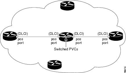
General Guidelines for Switched PVC Configuration
The DLCI number has a per-hop significance, not an end-to-end significance: the two interfaces connected together via POS links must have the same DLCI number, but the two interfaces that form the switched PVC can use different DLCI numbers.
Example
Figure 1 shows a generic PVC configuration:
•
•
•
Note
Note
Example: if an interface is already configured with standard addressing, typing "encapsulation frame-relay extended" will cause all existing routes to disappear from the interface. These routes must be re-entered. This will also occur if an interface with Extended Addressing is re-configured as a standard Frame-Relay interface.Figure 1 Generic Frame Relay Switched PVC example
Configuring Frame Relay Extended Addressing
This section contains instructions to configure a switched Frame Relay PVC with Extended Addressing. Please note the following before beginning:
•
•
•
–
–
•
Note
This section contains configuration instructions for the following two scenarios:
•
•
Configuring a Switched PVC between two Interfaces with Frame Relay Extended Addressing
This section contains instructions to configure a PVC between two interfaces with Extended Addressing.
•
•
Table 1
Configure Frame Relay Switching, Extended Addressing Encapsulation and Switched PVCs on first port
Table 2
Configure Extended Addressing Encapsulation and Switched PVCs on second port
Note
Configuring a Switched PVC between Extended Addressing and Non-Extended Addressing Interfaces
A PVC can also be configured for switching between an extended address and a non-extended address.
Note
A sample configuration is show in this section:
•
•
Table 3
Configure the First Interface with Standard DLCI Values
Table 4
Configure the Second Interface with Extended Addressing
Note
Verifying the Frame Relay Interface and Switched PVCs
Use the following show commands to verify that Frame Relay switched PVCs are enabled:
Router# show frame-relay route
Displays switched Frame Relay PVCs.
Router# show frame-relay pvc
Displays all PVCs configured on the router.
Configuration Examples
This section provides the following configuration examples:
•
•
Frame Relay Interface and Switched PVCs configuration
router#config terminalEnter configuration commands, one per line. End with CNTL/Z.router(config)#frame-relay switchingrouter(config)#interface pos3/1router(config-if)#encapsulation frame-relay extendedrouter(config-if)#frame-relay nni-annex1router(config-if)#frame-relay route 5000 interface pos3/0 200router(config-if)#exitrouter(config)#interface pos3/0router(config-if)#encapsulation frame-relayrouter(config-if)#frame-relay intf-type dcerouter(config-if)#frame-relay route 200 interface pos3/1 5000router(config-if)#endrouter#008619: 3w4d: %SYS-5-CONFIG_I: Configured from console by consolerouter#show running interface pos3/1Building configuration...Current configuration:!interface POS3/1no ip addressno ip directed-broadcastencapsulation frame-relay extendedcrc 16clock source internalframe-relay intf-type nniframe-relay nni-annex1frame-relay route 5000 interface POS3/0 200frame-relay lapf n201 4470endshow frame-relay pvc interface
router#show frame-relay pvc interface pos3/1 4000PVC Statistics for interface POS3/1 (Frame Relay NNI)DLCI = 4000, DLCI USAGE = SWITCHED, PVC STATUS = INACTIVE, INTERFACE = POS3/1LOCAL PVC STATUS = INACTIVE, NNI PVC STATUS = ACTIVEinput pkts 5 output pkts 5 in bytes 520out bytes 520 dropped pkts 0 in FECN pkts 0in BECN pkts 0 out FECN pkts 0 out BECN pkts 0in DE pkts 0 out DE pkts 0out bcast pkts 0 out bcast bytes 0switched pkts 10Detailed packet drop counters:no out intf 0 out intf down 0 no out PVC 0in PVC down 0 out PVC down 0 pkt too big 0pvc create time 3w4d, last time pvc status changed 1w0dshow frame-relay route
router#show frame-relay routeInput Intf Input Dlci Output Intf Output Dlci StatusPOS3/1 21 POS3/0 20 inactivePOS3/1 230 POS5/0 230 inactivePOS3/2 100 POS5/2 100 inactivePOS3/2 230 POS5/2 230 inactivePOS5/0 100 POS3/1 100 inactivePOS5/0 230 POS3/1 230 inactivePOS5/2 100 POS3/2 100 inactivePOS5/2 230 POS3/2 230 inactivePOS3/1 2100 POS5/0 100 inactive
Note
Command Reference
To enable Extended Addressing for Frame Relay, a new a new encapsulation type has been added to the command encapsulation frame-relay:
•
All other commands used with this feature are documented in the Cisco IOS Release 12.0 command reference publications. These publications are summarized in the "Related Documents" section.
encapsulation frame-relay [extended]
To enable Extended Addressing for Frame Relay, a new option has been added to the encapsulation frame-relay interface configuration command.
Use the encapsulation frame-relay extended interface configuration command to enable Extended Addressing. To disable Frame Relay Extended Addressing encapsulation, use the no form of this command.
encapsulation frame-relay [extended]
no encapsulation frame-relay [extended]
Syntax Description
extended
This option enables 23-bit DLCIs for Frame Relay NNI interfaces to support DLCI values between 16 and 8388607.
Defaults
No default behavior or values.
Command Modes
Interface configuration
Command History
10.0
The encapsulation frame-relay command was introduced.
12.0(17)S
The command was modified to include the [extended] option.
Usage Guidelines
Frame Relay Extended Addressing supports DLCI values between 16 and 8388607. Support for Extended Addressing is restricted to the following features:
•
•
•
•
See the "Restrictions" section for more information on other commands and features supported with Frame Relay Extended Addressing.
Examples
The following example configures Cisco Frame Relay encapsulation on interface serial 1:
interface serial 1
encapsulation frame-relay extendedDebug Commands
No new or modified debug commands were introduced with Frame Relay Extended Addressing.
See the "Restrictions" section for more information on the debug commands supported by Extended Addressing through the feature "Switching Diagnostics and Troubleshooting".
Glossary
CLI—Command Line Interface
DCE—Data Circuit-terminating Equipment
DLCI—Data Link Connection Identifier
NNI—Network-to-Network Interface
POS—PAcket Over Sonnet
PVC—Permanent Virtual Circuit
SNMP—Simple Network Management Protocol
UNI—User-to-Network Interface