Downloads |
 Feedback Feedback
|
Table Of Contents
Prerequisites for the MPLS VPNs over IP Tunnels Feature
Supported Line Cards for the Cisco 12000 Series Internet Router
Supported Line Cards for the Cisco 10720 Internet Router
Restrictions for the MPLS VPNs over IP Tunnels Feature
MPLS VPNs over IP Tunnels Feature Information
Deploying Layer 3 VPNs Over Multipoint L2TPv3 Tunnels
Advertising Tunnel Type and Tunnel Capabilities Between PE Routers—BGP
Configuring the PE Routers and Managing Address Space
Configuring Quality of Service Using the Modular QoS CLI
MPLS VPN Carrier Supporting Carrier over IP Tunnels
BGP Multipath Load Sharing for MPLS VPNs over IP Tunnels
Configuring MPLS VPNs over IP Tunnels
Configuring a VRF for an L2TPv3 Tunnel
Configuring a Multipoint L2TPv3 Tunnel
Configuring a Route Map for a Layer 3 VPN
Defining an Address Space and Configuring BGP
Configuring Tunnel Marking on an Encapsulation Interface
Mapping Tunnel Marking to QoS-group and Discard-Class
Configuring MPLS VPN Carrier Supporting Carrier over IP Tunnels
Configuring the Backbone-Carrier PE Router
Configuring the Customer-Carrier PE Router
Verifying the Multipoint L2TPv3 Tunnel
Verifying the Modular QoS CLI Configuration
Verifying the MPLS VPN—Carrier Supporting Carrier Configuration
Configuration Examples for MPLS VPNs over IP Tunnels
Configuring the VRF and RiV—Example
Configuring the Multipoint L2TPv3 Tunnel—Example
Configuring a Route Map for the Layer 3 VPN—Example
Defining Address Space and Configuring BGP—Example
Configuring Tunnel Marking on the Encapsulation Interface—Example
Mapping Tunnel Marking to QoS-group and Discard-Class—Example
Configuring MPLS VPN Carrier Supporting Carrier over IP Tunnels—Examples
Configuration for an ISP Customer Carrier
Configuration for an MPLS VPN Customer Carrier
Verifying the Multipoint L2TPv3 Tunnel—Examples
Verifying QoS Configuration—Example
Verifying MPLS VPN Carrier Supporting Carrier over IP Tunnels—Example
MPLS VPNs over IP Tunnels
Part Number OL-8694-01 (Rev C0), September 26, 2006
The MPLS VPNs over IP Tunnels feature introduces the capability to deploy Layer 3 Virtual Private Network (VPN) services, as proposed in RFC 2547, BGP/MPLS VPNs, over an IP core network using L2TPv3 multipoint tunneling instead of Multiprotocol Label Switching (MPLS). This feature allows L2TPv3 tunnels to be configured as multipoint tunnels to transport IP VPN services across the core IP network. Because multipoint tunnels support multiple endpoints, only one tunnel must be configured on each Provider Edge (PE) router. This feature also introduces a simple packet validation mechanism to enforce VPN integrity.
Feature History for MPLS VPNs over IP Tunnels
12.0(28)S
This feature was introduced.
12.0(30)S
Support for the Cisco 12000 Series Internet Router, the Route Processor (RP), and Performance Route Processor (PRP) was integrated into Cisco IOS Release 12.0(30)S.
12.0(31)S
Support for the MPLS VPNs over IP Tunnels feature was added on the Cisco 12000 series Internet router on the following interfaces:
•
2.5G ISE SPA Interface Processor (SIP):
–
–
–
–
Support for the MPLS VPN—Carrier Supporting Carrier (CsC) feature on interfaces configured for MPLS VPNs over IP Tunnels was added to IP Services Engine (ISE) line cards on the Cisco 12000 series Internet router.
12.0(31)S1
Support was added for Cisco 12000 series ISE line cards that are configured for external BGP (eBGP) and internal BGP (iBGP) multipath load balancing in a BGP MPLS-VPN network (see BGP Multipath Load Sharing for Both eBGP and iBGP in an MPLS-VPN).
12.0(32)S
Support for the Cisco 10720 Internet router was added.
12.0(32)SY
Support was added for Engine 5 shared port adapters (SPAs) and SPA Interface Processors (SIPs) on the Cisco 12000 series Internet router.
Support for E5 interfaces configured for eBGP and iBGP multipath load sharing in a BGP MPLS network was also added (see BGP Multipath Load Sharing for Both eBGP and iBGP in an MPLS-VPN).
Support for the MPLS VPN Carrier Supporting Carrier over IP Tunnels feature on customer-facing interfaces on the Cisco 10720 Internet router was added.
Finding Support Information for Platforms and Cisco IOS Software Images
To use Cisco Feature Navigator to find information about platform support and Cisco IOS software image support, go to http://www.cisco.com/go/fn. You must have an account on Cisco.com. If you do not have an account or have forgotten your username or password, click Cancel at the login dialog box and follow the instructions.
Contents
•
•
•
•
•
Prerequisites for the MPLS VPNs over IP Tunnels Feature
CEF or dCEF (for distributed platforms) must be enabled on all participating routers.
Supported Line Cards for the Cisco 12000 Series Internet Router
This section lists the Cisco 12000 series Internet router line cards that support the MPLS VPNs over IP Tunnels feature with backbone-facing interfaces (BFIs) in the network core and customer-facing interfaces (CFI) on the network edge.
Supported Backbone-Facing Interfaces
•
•
•
•
•
•
•
2-port channelized T3 to DS0
4-port channelized T3 to DS0
2-port T3/E3 Serial
4-port T3/E3 Serial
•
1-port channelized STM-1c/OC-3c to DS0
2-port channelized T3 to DS0
4-port channelized T3 to DS0
8-port channelized T1/E1
1-port 10-Gigabit Ethernet
2-port Gigabit Ethernet
5-port Gigabit Ethernet
10-port Gigabit Ethernet
8-port Fast Ethernet
8-port 10/100 Ethernet
4-port OC-3/STM4 POS
8-port OC-3/STM4 POS
2-port OC-12/STM4 POS
4-port OC-12/STM4 POS
8-port OC-12/STM4 POS
2-port OC-48/STM16 POS/RPR
1-port OC-192/STM64 POS/RPR VSR
1-port OC-192/STM64 POS/RPR SMLR
1-port OC-192/STM64 POS/RPR XFP
•
12000-SIP-400 (2.5G ISE SPA Interface Processor)
12000-SIP-600 (10G Engine 5 SPA Interface Processor)
12000-SIP-401 (2.5G multiservice engine SPA Interface Processor)
12000-SIP-501 (5G multiservice engine SPA Interface Processor)
12000-SIP-601 (10G multiservice engine SPA Interface Processor)
Supported Customer-Facing Interfaces
•
•
•
•
•
•
•
•
•
•
2-port channelized T3 to DS0
4-port channelized T3 to DS0
2-port T3/E3 Serial
4-port T3/E3 Serial
•
1-port channelized STM-1c/OC-3c to DS0
8-port channelized T1/E1
1-port 10-Gigabit Ethernet
2-port Gigabit Ethernet
5-port Gigabit Ethernet
10-port Gigabit Ethernet
8-port Fast Ethernet
8-port 10/100 Ethernet
4-port OC-3/STM4 POS
8-port OC-3/STM4 POS
2-port OC-12/STM4 POS
4-port OC-12/STM4 POS
8-port OC-12/STM4 POS
2-port OC-48/STM16 POS/RPR
1-port OC-192/STM64 POS/RPR
1-port OC-192/STM64 POS/RPR
1-port OC-192/STM64 POS/RPR
•
12000-SIP-400 (2.5G ISE SPA Interface Processor)
12000-SIP-600 (10G Engine 5 SPA Interface Processor
12000-SIP-401 (2.5G multiservice engine SPA Interface Processor)
12000-SIP-501 (5G multiservice engine SPA Interface Processor)
12000-SIP-601 (10G multiservice engine SPA Interface Processor)
Supported Line Cards for the Cisco 10720 Internet Router
This section describes the Cisco 10720 Internet router line cards that support the MPLS VPNs over IP Tunnels feature on backbone-facing and customer-facing interfaces.
Supported Backbone-Facing Interfaces on Uplink Cards
•
•
•
•
Supported Customer-Facing Interfaces on Access Cards
•
•
802.1Q VLAN encapsulation is supported on these backbone-facing and customer-facing 10720 interfaces when they are configured as member interfaces of a Fast EtherChannel or Gigabit EtherChannel bundle.
For more information about supported line cards, see the Cross-Platform Release Notes for Cisco IOS Release 12.0 S.
Restrictions for the MPLS VPNs over IP Tunnels Feature
Configuring Static Routes
When you configure static routes in an MPLS or MPLS VPN network, some variations of the ip route and ip route vrf commands are not supported for the MPLS VPNs over IP Tunnels feature in the following trains of Cisco IOS software that support the Tag Forwarding Information Base (TFIB):
•
•
•
The TFIB cannot resolve prefixes when the recursive route over which the prefixes travel disappears and then reappears. However, certain command variations are supported in Cisco IOS releases that support the MPLS Forwarding Infrastructure (MFI), such as Cisco IOS Release 12.2(25)S and later releases. Refer to Table 1 and Table 2 for the ip route and ip route vrf commands that are supported and not supported when configuring static routes in an MPLS environment.
Table 1 describes the ip route and ip route vrf commands that are supported to configure static routes in an IP core network configured for MPLS VPNs over IP Tunnels.
Table 2 describes the ip route and ip route vrf commands that are not supported to configure static routes in an IP core network configured for MPLS VPNs over IP Tunnels.
MPLS VPNs over IP Tunnels Feature Information
•
•
•
•
•
•
Deploying Layer 3 VPNs Over Multipoint L2TPv3 Tunnels
VPN services are traditionally deployed over IP core networks by configuring MPLS or through L2TPv3 tunnels using point-to-point links. This feature introduces the capability to deploy Layer 3 VPN services by configuring multipoint L2TPv3 tunnels over an existing IP core network. This feature is configured only on PE routers and requires no configuration on the core routers.
The L2TPv3 multipoint tunnel network allows Layer 3 VPN services to be carried through the core without the configuration of MPLS. L2TPv3 multipoint tunnelling supports multiple tunnel endpoints, which creates a full mesh topology that requires only one tunnel to be configured on each PE router. This feature provides the capability for VPN traffic to be carried from enterprise networks across cooperating service provider core networks to remote sites.
Advertising Tunnel Type and Tunnel Capabilities Between PE Routers—BGP
Border Gateway Protocol (BGP) is used to advertise the tunnel endpoints and the subaddress family identifier (SAFI) specific attributes (which contains the tunnel type, and tunnel capabilities). This feature introduces the tunnel SAFI and the BGP SAFI-Specific Attribute (SSA) attribute.
The tunnel SAFI:
•
•
The BGP SSA:
•
•
These attributes allow BGP to distribute tunnel encapsulation information between PE routers. VPNv4 traffic is routed through these tunnels. The next hop, advertised in BGP VPNv4 updates, determines which tunnel to use for routing tunnel traffic.
Configuring the PE Routers and Managing Address Space
One multipoint L2TPv3 tunnel is configured on each PE router. To create the VPN, configure a unique Virtual Routing and Forwarding (VRF) instance. The tunnel that transports the VPN traffic across the core network resides in its own address space. A special purpose VRF called a Resolve in VRF (RiV) is created to manage the tunnel address space. You also configure the address space under the RiV that is associated with the tunnel and a static route in the RiV to route outgoing traffic through the tunnel.
Packet Validation Mechanism
The MPLS VPNs over IP Tunnels feature provides a simple mechanism to validate received packets from appropriate peers. The multipoint L2TPv3 tunnel header is automatically configured with a 64-bit cookie and L2TPv3 session ID. This packet validation mechanism protects the VPN from illegitimate traffic sources, such as injecting a rogue packet into the tunnel to gain access to the VPN. The cookie and session ID are not user-configurable; however, they are visible in the packet as it is routed between the two tunnel endpoints. This packet validation mechanism does not protect the VPN from hackers who have the ability to monitor legitimate traffic between PE routers.
Configuring Quality of Service Using the Modular QoS CLI
To configure the bandwidth on the encapsulation and decapsulation interfaces, use the modular QoS CLI (MQC). This task is optional.
Use the MQC to configure the IP precedence or Differentiated Services Code Point (DSCP) value set in the IP carrier header during packet encapsulation. To set these values, enter a standalone set command or a police command using the keyword tunnel. In the input policy on the encapsulation interface, you can set the precedence or DSCP value in the IP payload header by using MQC commands without the keyword tunnel.
Note
If Modified Deficit Round Robin (MDRR)/Weighted Random Early Detection (WRED) is configured for the encapsulation interface in the input direction, the final value of the precedence or DSCP field in the IP carrier header is used to determine the precedence class for which the MDRR/WRED policy is applied. On the decapsulation interface in the input direction, you can configure a QoS policy based on the precedence or DSCP value in the IP carrier header of the received packet. In this case, an MQC policy with a class to match on precedence or DSCP value will match the precedence or DSCP value in the received IP carrier header.
Similarly, the precedence class for which the MDRR/WRED policy is applied on the decapsulation input direction is also determined by precedence or DSCP value in the IP carrier header.
MPLS VPN Carrier Supporting Carrier over IP Tunnels
You can configure the MPLS VPN—Carrier Supporting Carrier (CsC) feature on the following interfaces that are configured for the MPLS VPNs over IP Tunnels feature:
•
•
The router must be deployed as a PE router in a service-provider core network. The MPLS VPN Carrier Supporting Carrier over IP Tunnels feature is supported only on customer-facing interfaces.
Note
The MPLS VPN Carrier Supporting Carrier over IP Tunnels feature enables one MPLS VPNs over IP Tunnel-based service provider to allow other service providers to use a segment of its backbone network.
•
•
The backbone carrier benefits in the following ways:
•
•
The MPLS VPN—Carrier Supporting Carrier feature focuses on a backbone carrier that offers Border Gateway Protocol and Multiprotocol Label Switching (BGP/MPLS) VPN services.
When you configure the MPLS VPN—Carrier Supporting Carrier feature on a Cisco 12000 series Internet router, the customer carrier can be either:
•
•
For sample configurations of the MPLS VPN—Carrier Supporting Carrier feature for each type of customer carrier, see Configuring MPLS VPN Carrier Supporting Carrier over IP Tunnels—Examples.
When configured on a Cisco 10720 Internet router, the MPLS VPN—Carrier Supporting Carrier feature supports only customer-carrier VPNs that are configured as an MPLS VPN over IP Tunnels network.
For information about configuring a backbone carrier for the Carrier Supporting Carrier feature to allow other service providers to use a segment of its backbone network, refer to:
•
•
BGP Multipath Load Sharing for MPLS VPNs over IP Tunnels
You can configure external BGP (eBGP) and internal BGP (iBGP) multipath load balancing on the following customer-facing interfaces that are configured for the MPLS VPNs over IP Tunnels feature:
•
•
The BGP Multipath Load Sharing for eBGP and iBGP feature:
•
•
For information about how to configure and use BGP multipath load sharing for both eBGP and iBGP paths, refer to BGP Multipath Load Sharing for Both eBGP and iBGP in an MPLS-VPN.
Configuring MPLS VPNs over IP Tunnels
To deploy Layer 3 VPN services over multipoint L2TPv3 tunnels, you create a VRF instance, create the multipoint L2TPv3 tunnel, redirect the VPN IP traffic to the tunnel, and configure the BGP VPNv4 exchange so that BGP updates are filtered through a route-map and prefixes are resolved in the VRF table. The configuration steps are described in the following sections:
•
•
•
•
•
•
•
•
•
•
Configuring a VRF for an L2TPv3 Tunnel
The VPN is created by configuring a unique Virtual Routing and Forwarding (VRF) instance. The tunnel that transports the VPN traffic across the core network resides in its own address space. A special purpose VRF called a Resolve in VRF (RiV) is created to manage the tunnel address space.
SUMMARY STEPS
1.
2.
3.
4.
5.
6.
7.
8.
9.
10.
DETAILED STEPS
Proceed to the next task "Configuring a Multipoint L2TPv3 Tunnel."
Configuring a Multipoint L2TPv3 Tunnel
Border Gateway Protocol (BGP) is used to advertise the tunnel type, tunnel capabilities, and tunnel-specific attributes. BGP is also used to distribute VPNv4 routing information between PE routers on the edge of the network, which maintains peering relationships between the VPN service and VPN sites. The next hop advertised in BGP VPNv4 updates triggers tunnel endpoint discovery.
Prerequisites
The IP address of the interface, specified as the tunnel source, should match the IP address used by BGP as the next hop for the VPNv4 update. The BGP configuration will include the neighbor ip-address update-source loopback 0 command.
SUMMARY STEPS
1.
2.
3.
4.
5.
6.
7.
8.
DETAILED STEPS
Troubleshooting
To generate and distribute a new L2TPv3 session for a Layer 3 VPN, use the clear tunnel l3vpn l2tpv3 command. This command is issued on the PE router. The hold-time argument is used to configure the amount of time that the existing session remains valid, while the new session is propagated to peers. The default value for the hold-time argument is 15 seconds. This is enough time for most networks. However, this value can be increased if it takes longer for the new session to propagate to all other PE routers.
Proceed to the next task "Configuring a Route Map for a Layer 3 VPN."
Configuring a Route Map for a Layer 3 VPN
Configure a route map to set the next hop to be resolved within the VRF table.
SUMMARY STEPS
1.
2.
3.
4.
5.
DETAILED STEPS
Proceed to the next task "Defining an Address Space and Specifying Address Resolution."
Defining an Address Space and Configuring BGP
Use the configuration task procedure in this section to set up the BGP VPNv4 exchange so that the updates are filtered through a route-map and interesting prefixes are resolved in the VRF table. The tunnel that transports the VPN traffic across the BGP core network resides in its own address space. The RiV is specified in this configuration to direct packet forwarding and next hop resolution.
SUMMARY STEPS
1.
2.
3.
4.
5.
6.
7.
8.
9.
10.
11.
12.
13.
DETAILED STEPS
Proceed to the next task "Configuring Tunnel Marking on an Encapsulation Interface."
Configuring Tunnel Marking on an Encapsulation Interface
QoS can optionally be configured to control bandwidth. As part of encapsulation, the precedence or Differentiated Services Code Point (DSCP) value in the IP carrier header can be set using the MQC. This can be achieved by configuring a standalone set action or by configuring a policing action using the keyword tunnel. In the input policy on the encapsulation interface, the precedence or DSCP value in the IP payload header can be set using MQC commands without using the keyword tunnel. Sample configurations appear below.
Note
If Modified Deficit Round Robin (MDRR)/Weighted Random Early Detection (WRED) is configured for the encapsulation interface in the input direction, the final value of the precedence or DSCP field in the IP carrier header is used to determine the precedence class for which the MDRR/WRED policy is applied.
Release 12.0(32)SY adds scaled QoS capabilities on the Cisco 12000 platform by manipulating the tunnel header on the ingress PE. This will allow you to provide transparent QoS services by deliver end-to-end QoS enabled MVPN services,
SUMMARY STEPS
1.
2.
3.
4.
5.
or
set ip precedence tunnel precedence-value
or
police bps [burst-normal] [burst-max] conform-action action exceed-action action
6.
7.
8.
9.
10.
11.
12.
13.
DETAILED STEPS
Step 1
enable
Example:Router> enable
Enables privileged EXEC mode.
•
Step 2
configure terminal
Example:Router# configure terminal
Enters global configuration mode.
Step 3
policy-map policy-map-name
Example:Router(config)# policy-map set_prec_tun
Creates or modifies a policy map that can be attached to one or more interfaces to specify a service policy, and enters policy-map configuration mode.
•
Step 4
class {class-name | class-default}
Example:Router(config-pmap)# class class-default
Specifies the name of the class whose policy you want to create or change, or specifies the default class (commonly known as the class-default class) before you configure its policy. Also enters policy-map class mode.
•
Step 5
set ip dscp tunnel dscp-value
Example:Router(config-pmap-c)# set ip dscp tunnel 2
(Optional) Sets or marks the differentiated services code point (DSCP) value in the tunnel header on the ingress interface. The tunnel marking value is a number from 0 to 63 when configuring DSCP.
•
or
set ip precedence tunnel precedence-value
Example:Router(config-pmap-c)# set ip precedence tunnel 2
(Optional) Sets or marks the IP precedence value in the tunnel header on the ingress interface. The tunnel marking value is a number from 0 to 7 when configuring IP precedence.
•
or
police bps [burst-normal] [burst-max] conform-action action exceed-action action
Example:Router(config-pmap-c)# police 1280000 conform-action set-dscp-tunnel-transmit 3
exceed-action drop
or
Router(config-pmap-c)# police cir 1280000
conform-action set-prec-tunnel-transmit 3
exceed-action drop
(Optional) Configures traffic policing on the basis of the bits per second (bps) specified and the actions specified.
If you use traffic policing in your network, you can implement the L2TPv3 tunnel marking feature with the set-dscp-tunnel-transmit or set-prec-tunnel-transmit traffic policing commands instead of the set ip dscp tunnel or the set ip precedence tunnel commands shown in Step 5.
The tunnel marking value for the traffic policing commands is from 0 to 63 when using set-dscp-tunnel-transmit and from 0 to 7 when using set-prec-tunnel-transmit.
•
•
Note
Step 6
exit
Example:Router(config-pmap-c)# exit
Exits policy-map class configuration mode and enters policy-map configuration mode.
Step 7
exit
Example:Router(config-pmap)# exit
Exits policy-map configuration mode and enters global configuration mode.
Step 8
interface type number [name-tag]
Example:Router(config)# interface POS0/0
Configures the interface type specified and enters interface configuration mode.
•
Step 9
description string
Example:Router(config-if)# description IP VPN Encapsulation - Customer Facing
Adds a description to the interface configuration.
Step 10
ip vrf forwarding vrf-name
Example:Router(config-if)# ip vrf forwarding IP_VPN
Associates the VRF with an interface or the subinterface.
Step 11
ip address ip-address mask [secondary]
Example:Router(config-if)# ip address 192.168.123.4 255.255.255.0
Sets a primary or secondary IP address for an interface.
Step 12
service-policy {input | output} policy-map-name
Example:Router(config-if)# service-policy input set_prec_tun
Specifies the name of the policy map to be attached to the input or output direction of the interface.
•
•
Note
Step 13
end
Example:Router(config-if)# end
(Optional) Exits interface configuration mode, and enters privileged EXEC mode.
Proceed to the next task "Mapping Tunnel Marking to Qos-group and Discard-Class."
Mapping Tunnel Marking to QoS-group and Discard-Class
On the decapsulation interface in the input direction, the QoS policy can be constructed based on the IP precedence or DSCP value in the IP carrier header of the received packet. In this case, an MQC policy with a class to match on precedence or DSCP value matches the IP precedence or DSCP value in the received IP carrier header.
Similarly, the IP precedence class (for which the MDRR/WRED policy is applied on the decapsulation input direction) is also determined by the IP precedence or DSCP value in the IP carrier header. Qos-group and discard-class values can then be used to construct an output policy for the Decapsulation interface to configure Modified Deficit Round Robin (MDRR)/Weighted Random Early Detection (WRED).
SUMMARY STEPS
1.
2.
3.
4.
5.
6.
7.
8.
9.
10.
11.
12.
13.
14.
DETAILED STEPS
Proceed to the sections, Verifying the VRF and RiV and Verifying the Multipoint L2TPv3 Tunnel, to verify the configuration of the MPLS-VPNs over IP Tunnels feature.
Configuring MPLS VPN Carrier Supporting Carrier over IP Tunnels
To enable a backbone carrier to share its backbone network, configured for the MPLS VPNs over IP Tunnels feature with a customer carrier, you must perform the following tasks:
1.
2.
This section describes how to perform each task. For more detailed information about the configuration procedure and command syntaxes, refer to the "Configuration Tasks" section in the MPLS VPN—Carrier Supporting Carrier and MPLS VPN—Carrier Supporting Carrier—IPv4 BGP Label Distribution documents.
Prerequisites
•
•
•
•
–
–
•
•
•
–
–
–
–
–
Configuring the Backbone-Carrier PE Router
SUMMARY STEPS
1.
2.
3.
4.
5.
DETAILED STEPS
Step 1
enable
Example:Router> enable
Enables privileged EXEC mode.
•
Step 2
configure terminal
Example:Router# configure terminal
Enters global configuration mode.
Step 3
mpls label protocol ldp
Example:Router(config)# mpls label protocol ldp
Sets the default label distribution protocol for all interfaces to be LDP.
Step 4
mpls ip
Example:Router(config)# mpls ip
Enables MPLS on the VRF interface of the PE router in the backbone-carrier network, as configured in Configuring a VRF for an L2TPv3 Tunnel.
Step 5
end
Example:Router(config-if)# end
Exits global configuration mode, and enters privileged EXEC mode.
Configuring the Customer-Carrier PE Router
SUMMARY STEPS
1.
2.
3.
4.
5.
DETAILED STEPS
Step 1
enable
Example:Router> enable
Enables privileged EXEC mode.
•
Step 2
configure terminal
Example:Router# configure terminal
Enters global configuration mode.
Step 3
mpls label protocol ldp
Example:Router(config)# mpls label protocol ldp
Sets the default label distribution protocol for all interfaces to be LDP.
Step 4
mpls ip
Example:Router(config)# mpls ip
Enables MPLS on the VRF interface of the CE router in the customer-carrier network, as configured in Configuring a VRF for an L2TPv3 Tunnel.
Step 5
end
Example:Router(config-if)# end
Exits global configuration mode, and enters privileged EXEC mode.
1.
2.
Verifying the VRF and RiV
Use the following steps to verify the configuration of the VRF and RiV.
SUMMARY STEPS
1.
2.
3.
4.
DETAILED STEPS
Verifying the Multipoint L2TPv3 Tunnel
Use the following steps to verify the configuration of the multipoint L2TPv3 tunnel.
SUMMARY STEPS
1.
2.
3.
4.
5.
DETAILED STEPS
Verifying the Modular QoS CLI Configuration
To verify that this feature is configured as intended and that either the IP precedence or DSCP value is set as expected, complete the following steps.
SUMMARY STEPS
1.
2.
or
show policy-map policy-map
3.
DETAILED STEPS
Troubleshooting Tips
Use the commands in the "Verifying the Modular QoS CLI Configuration" section to verify that you achieved the intended configuration and that the feature is functioning correctly. If, after using the show commands listed above, you find that the configuration is not correct or the feature is not functioning as expected, perform these operations:
If the configuration is not the one you intended, complete the following procedures:
•
•
Verifying the MPLS VPN—Carrier Supporting Carrier Configuration
To verify the MPLS VPN—Carrier Supporting Carrier feature on interfaces configured for MPLS VPNs over IP Tunnels on PE routers in a backbone carrier network:
1.
2.
To verify the status of LDP sessions between the backbone carrier and customer carrier configured for the MPLS VPN—Carrier Supporting Carrier feature, complete the following steps. The customer-carrier sites should appear as a VPN customer to the backbone carrier.configured for the MPLS VPNs over IP Tunnels feature.
SUMMARY STEPS
1.
2.
or
show mpls ldp discovery all
3.
DETAILED STEPS
Step 1
enable
Example:Router> enable
Enables privileged EXEC mode.
•
Step 2
show mpls ldp discovery vrf vpn-name
Example:Router# show mpls ldp discovery vrf vpn1
(Optional) Displays the neighbor discovery information for the specified VPN routing/forwarding instance (vpn-name).
•
or
show mpls ldp discovery all
Example:Router# show mpls ldp discovery all
(Optional) Displays LDP discovery information for all VPNs, including those in the default routing domain.
Step 3
exit
Example:Router# exit
Exits privileged EXEC mode.
Configuration Examples for MPLS VPNs over IP Tunnels
•
•
•
•
•
•
•
•
•
•
Note
Configuring the VRF and RiV—Example
The following sample configuration creates and configures the VRF and RiV:
ip vrf vrf-namerd 100:110route-target import 100:1000route-target export 100:1000exitip vrf MY_RIVrd 1:1endConfiguring the Multipoint L2TPv3 Tunnel—Example
The following sample configuration creates and configures the L2TPv3 tunnel:
interface tunnel 1ip vrf forwarding MY_RIVip-address 172.16.1.3 255.255.255.255tunnel source loopback 0tunnel mode l3vpn l2tpv3 multipointendConfiguring a Route Map for the Layer 3 VPN—Example
The following sample configuration creates an inbound route map to set the next hop to be resolved within the VRF:
route-map SELECT_UPDATE_FOR_L3VPN permit 10set ip next-hop in-vrf MY_RIVendDefining Address Space and Configuring BGP—Example
The following sample configuration defines address space for the VPN and configures BGP:
ip route vrf MY_RIV 0.0.0.0 0.0.0.0 tunnel 1router bgp 100neighbor 172.16.1.2 remote-as 100neighbor 172.16.1.2 update-source Loopback 0address-family vpnv4 unicastneighbor 172.16.1.2 activateneighbor 172.16.1.2 route-map SELECT_UPDATE_FOR_L3VPN inexit-address-familyaddress-family ipv4 tunnelneighbor 176.16.1.2 activateendConfiguring Tunnel Marking on the Encapsulation Interface—Example
The following examples show how to configure QoS to control bandwidth. These examples show how to configure IP precedence or DSCP using individual set actions or by configuring policing actions.
In the following example, a policy map named "set_prec_tun" is created and the IP precedence is configured in the policy map. You could use the set ip dscp tunnel command instead of the set ip precedence tunnel command if you do not use IP precedence in your network.
policy-map set_prec_tunclass class-defaultset ip precedence tunnel 2set ip precedence 2In the following example, the IP precedence is configured as a policing action using the police command. Like the previous example, DSCP or IP precedence can be configured.
policy-map policer_prec_tunclass class-defaultpolice cir 1280000 conform-action set-prec-tunnel-transmit 3 exceed-action dropThe following example attaches the policy map to the interface. This step is required regardless of which method is used to configure IP precedence or DSCP.
interface POS0/0description IP VPN Encapsulation - Customer Facingip vrf forwarding IP_VPNip address 192.168.123.4 255.255.255.0service-policy input set_prec_tunMapping Tunnel Marking to QoS-group and Discard-Class—Example
The following example configures the policy on the decapsulation interface in the input direction. The QoS policy can be constructed based on the precedence or DSCP value in the IP carrier header of the received packet. The MQC policy is configured to match on the IP precedence or DSCP value received in the IP carrier header.
policy-map set_qos_disc_from_precclass match_prec1set qos-group 1set discard-class 1class match_prec2set qos-group 2set discard-class 2class match_prec3set qos-group 3set discard-class 3class class-defaultset discard-class 4set qos-group 4The following example attaches the policy map to the interface:
interface POS1/0description IP VPN Decapsulation - Backbone Facingip address 192.168.234.5 255.255.255.0no ip directed-broadcastip router isisservice-policy input set_qos_disc_from_precConfiguring MPLS VPN Carrier Supporting Carrier over IP Tunnels—Examples
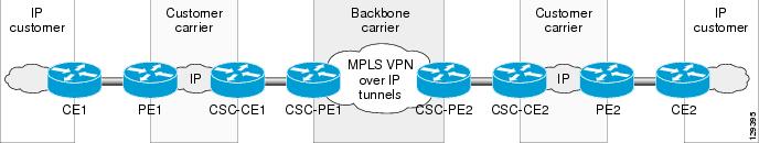
Figure 1 shows examples of how to configure the Carrier Supporting Carrier (CsC) feature on the interfaces of supported ISE and Engine 5 line cards in the PE routers of a backbone carrier (configured for the MPLS VPNs over IP Tunnels feature) and on the CE routers in one of the following types of customer carrier network:
•
•
Configuration for an ISP Customer Carrier
The following example shows how to configure the MPLS VPN Carrier Supporting Carrier over IP Tunnels feature for an ISP customer carrier to interconnect IP networks over a backbone MPLS VPNs over IP Tunnels network.
Figure 1 MPLS VPN Carrier Supporting Carrier over IP Tunnels for an ISP Customer Carrier
In this example, the following conditions apply:
•
•
•
•
For the MPLS VPN Carrier Supporting Carrier over IP Tunnels configuration shown in Figure 1, you must configure the two PE routers (CSC_PE1 and CSC-PE2) in the backbone carrier network and the two CE routers (CSC-CE1 and CSC-CE2) in the customer carrier networks, as described in the following sections.
CSC-CE1 Configuration
hostname csc-ce1mpls label protocol ldpinterface Loopback0ip address 10.100.2.2 255.255.255.255no ip directed-broadcastno ip route-cacheno ip mroute-cacheinterface Loopback1ip address 10.101.2.2 255.255.255.255no ip directed-broadcastno ip route-cacheinterface Loopback2ip address 10.102.2.2 255.255.255.255no ip directed-broadcastinterface POS2/0no ip addressno ip directed-broadcastencapsulation frame-relayno keepalivetag-switching ipcrc 32clock source internalinterface POS2/0.100 point-to-pointip address 192.168.80.4 255.255.255.0no ip directed-broadcastmpls label protocol ldptag-switching ipframe-relay interface-dlci 100interface POS2/0.200 point-to-pointip address 192.168.80.5 255.255.255.0no ip directed-broadcastmpls bgp forwardingframe-relay interface-dlci 200interface POS2/0.300 point-to-pointip address 192.168.80.6 255.255.255.0no ip directed-broadcastmpls label protocol ldptag-switching ipframe-relay interface-dlci 300interface POS2/0.400 point-to-pointip address 192.168.80.11 255.255.255.0no ip directed-broadcastframe-relay interface-dlci 400interface POS6/3no ip addressno ip directed-broadcastencapsulation frame-relayno keepalivecrc 32clock source internalinterface POS6/3.100 point-to-pointip address 192.168.70.4 255.255.255.0no ip directed-broadcastframe-relay interface-dlci 70interface POS6/3.200 point-to-pointip address 192.168.70.5 255.255.255.0no ip directed-broadcastmpls label protocol ldptag-switching ipframe-relay interface-dlci 200interface POS6/3.300 point-to-pointip address 192.168.70.6 255.255.255.0no ip directed-broadcastframe-relay interface-dlci 300router ospf 16log-adjacency-changesredistribute connected subnetsnetwork 192.168.70.4.0.0.0.255 area 100network 192.168.80.4.0.0.0.255 area 100router ospf 26log-adjacency-changesredistribute connected subnetsredistribute bgp 200 subnetsnetwork 192.168.70.5.0.0.0.255 area 200network 192.168.80.5.0.0.0.255 area 200router ospf 3log-adjacency-changesredistribute connected subnetsnetwork 192.168.70.6.0.0.0.255 area 3network 192.168.80.6.0.0.0.255 area 3network 10.102.2.2 0.0.0.0 area 3router bgp 200bgp log-neighbor-changesneighbor 192.168.80.5 remote-as 100neighbor 10.101.1.1 remote-as 200neighbor 10.101.1.1 update-source Loopback1neighbor 10.201.1.1 remote-as 200neighbor 10.201.1.1 update-source Loopback1neighbor 10.201.2.2 remote-as 200neighbor 10.201.2.2 update-source Loopback1address-family ipv4redistribute ospf 26neighbor 192.168.80.5 activateneighbor 192.168.80.5 send-labelno neighbor 10.101.1.1 activateno neighbor 10.201.1.1 activateno neighbor 10.201.2.2 activateno auto-summaryno synchronizationexit-address-familyaddress-family vpnv4neighbor 10.101.1.1 activateneighbor 10.101.1.1 send-community extendedneighbor 10.201.1.1 activateneighbor 10.201.1.1 send-community extendedneighbor 10.201.2.2 activateneighbor 10.201.2.2 send-community extendedexit-address-familyCSC-PE1 Configuration
hostname csc-pe1ip vrf forwardingip vrf my_rivrd 1:1ip vrf vpn100rd 100:100route-target export 100:100route-target import 100:100ip vrf vpn200rd 200:200route-target export 200:200route-target import 200:200ip vrf vpn300rd 300:300route-target export 300:300route-target import 300:300mpls label protocol ldpinterface Loopback0ip address 10.127.80.80 255.255.255.255no ip directed-broadcastip router isisno ip route-cacheinterface Tunnel100bandwidth 10000ip vrf forwarding my_rivip address 192.168.1.1 255.255.255.255no ip redirectsno ip directed-broadcasttunnel source Loopback0tunnel mode l3vpn l2tpv3 multipointinterface POS4/0no ip addressno ip directed-broadcastencapsulation frame-relayno keepalivempls label protocol ldptag-switching ipcrc 32clock source internalinterface POS4/0.100 point-to-pointip vrf forwarding vpn100ip address 192.168.80.4 255.255.255.0no ip directed-broadcastmpls label protocol ldptag-switching ipframe-relay interface-dlci 100interface POS4/0.200 point-to-pointip vrf forwarding vpn200ip address 192.168.80.5 255.255.255.0no ip directed-broadcastmpls bgp forwardingframe-relay interface-dlci 200interface POS4/0.300 point-to-pointip vrf forwarding vpn300ip address 192.168.80.6 255.255.255.0no ip directed-broadcastmpls label protocol ldptag-switching ipframe-relay interface-dlci 300interface POS5/0ip address 192.168.90.4 255.255.255.0no ip directed-broadcastip router isisno keepalivecrc 32clock source internalrouter ospf 16 vrf vpn100log-adjacency-changesredistribute bgp 100 subnetsnetwork 192.168.80.4.0.0.0.255 area 100router ospf 3 vrf vpn300log-adjacency-changesredistribute bgp 100 subnetsnetwork 192.168.80.6.0.0 0.255 area 3router isisnet 49.0001.0000.0000.000a.00router bgp 100bgp log-neighbor-changesneighbor 10.10.10.10 remote-as 100neighbor 10.10.10.10 update-source Loopback0neighbor 10.20.20.20 remote-as 100neighbor 10.20.20.20 update-source Loopback0neighbor 10.30.30.30 remote-as 100neighbor 10.30.30.30 update-source Loopback0address-family ipv4no neighbor 10.10.10.10 activateno neighbor 10.20.20.20 activateno neighbor 10.30.30.30 activateno auto-summaryno synchronizationexit-address-familyaddress-family ipv4 tunnelneighbor 10.10.10.10 activateneighbor 10.20.20.20 activateneighbor 10.30.30.30 activateexit-address-familyaddress-family vpnv4neighbor 10.10.10.10 activateneighbor 10.10.10.10 send-community bothneighbor 10.10.10.10 route-map rmap1 inneighbor 10.20.20.20 activateneighbor 10.20.20.20 send-community bothneighbor 10.20.20.20 route-map rmap1 inneighbor 10.30.30.30 activateneighbor 10.30.30.30 send-community bothneighbor 10.30.30.30 route-map rmap1 inexit-address-familyaddress-family ipv4 vrf vpn300redistribute connectedredistribute ospf 3 vrf vpn300no auto-summaryno synchronizationexit-address-familyaddress-family ipv4 vrf vpn200neighbor 192.168.80.5 remote-as 200neighbor 192.168.80.5 activateneighbor 192.168.80.5 as-overrideneighbor 192.168.80.5 send-labelno auto-summaryno synchronizationexit-address-familyaddress-family ipv4 vrf vpn100redistribute connectedredistribute ospf 16 vrf vpn100no auto-summaryno synchronizationexit-address-familyaddress-family ipv4 vrf my_rivno auto-summaryno synchronizationexit-address-familyaddress-family ipv4 vrf forwardingno auto-summaryno synchronizationexit-address-familyip route vrf my_riv 0.0.0.0 0.0.0.0 Tunnel100route-map rmap1 permit 10set ip next-hop in-vrf my_rivCSC-CE2 Configuration
hostname csc-ce2mpls label protocol ldpno mpls traffic-eng auto-bw timers frequency 0interface Loopback1ip address 10.201.2.2 255.255.255.255no ip directed-broadcastno ip route-cacheno ip mroute-cacheinterface POS12/0ip address 192.168.110.4 255.255.255.0no ip directed-broadcastno keepalivempls ldp discovery transport-address 11.11.11.11mpls label protocol ldptag-switching ipcrc 32clock source internalrouter ospf 17log-adjacency-changesredistribute connected subnetsnetwork 192.168.110.4.0.0.0.255 area 100router bgp 200bgp log-neighbor-changesneighbor 10.101.1.1 remote-as 200neighbor 10.101.1.1 update-source Loopback1neighbor 10.101.2.2 remote-as 200neighbor 10.101.2.2 update-source Loopback1neighbor 10.201.1.1 remote-as 200neighbor 10.201.1.1 update-source Loopback1address-family ipv4no neighbor 10.101.1.1 activateno neighbor 10.101.2.2 activateno neighbor 10.201.1.1 activateno auto-summaryno synchronizationexit-address-familyaddress-family vpnv4neighbor 10.101.1.1 activateneighbor 10.101.1.1 send-community extendedneighbor 10.101.2.2 activateneighbor 10.101.2.2 send-community extendedneighbor 10.201.1.1 activateneighbor 10.201.1.1 send-community extendedexit-address-familyip classlessip route 192.168.80.8 255.255.255.0 110.8.0.1ip route 192.168.80.11 255.255.255.0 110.11.0.1CSC-PE2 Configuration
hostname csc-pe2ip vrf forwardingip vrf my_rivrd 1:1ip vrf vpn100rd 100:100route-target export 100:100route-target import 100:100mpls label protocol ldpinterface Loopback0ip address 10.127.10.10 255.255.255.255no ip directed-broadcastip router isisinterface Loopback1ip vrf forwarding vpn100ip address 10.127.12.12 255.255.255.255no ip directed-broadcastinterface Tunnel100ip vrf forwarding my_rivip address 192.168.3.3 255.255.255.255no ip redirectsno ip directed-broadcasttunnel source Loopback0tunnel mode l3vpn l2tpv3 multipointinterface POS6/0ip address 192.168.100.4 255.255.255.0no ip directed-broadcastip router isiscrc 32clock source internalinterface POS8/0ip vrf forwarding vpn100ip address 192.168.110.4 255.255.255.0no ip directed-broadcastno keepalivempls ldp discovery transport-address 12.12.12.12mpls label protocol ldptag-switching ipcrc 32clock source internalrouter ospf 17 vrf vpn100log-adjacency-changesredistribute connected subnetsredistribute bgp 100 subnetsnetwork 192.168.110.4.0.0.0.255 area 100router isisnet 49.0001.0000.0000.000c.00router bgp 100no synchronizationbgp log-neighbor-changesneighbor 10.127.80.80 remote-as 100neighbor 10.127.80.80 update-source Loopback0no auto-summaryaddress-family ipv4 tunnelneighbor 10.127.80.80 activateexit-address-familyaddress-family vpnv4neighbor 10.127.80.80 activateneighbor 10.127.80.80 send-community bothneighbor 10.127.80.80 route-map rmap1 inexit-address-familyaddress-family ipv4 vrf vpn400redistribute connectedno auto-summaryno synchronizationexit-address-familyaddress-family ipv4 vrf vpn100redistribute connectedredistribute ospf 17 vrf vpn100no auto-summaryno synchronizationexit-address-familyaddress-family ipv4 vrf my_rivno auto-summaryno synchronizationexit-address-familyaddress-family ipv4 vrf forwardingno auto-summaryno synchronizationexit-address-familyip route vrf my_riv 0.0.0.0 0.0.0.0 Tunnel100route-map rmap1 permit 10set ip next-hop in-vrf my_rivConfiguration for an MPLS VPN Customer Carrier
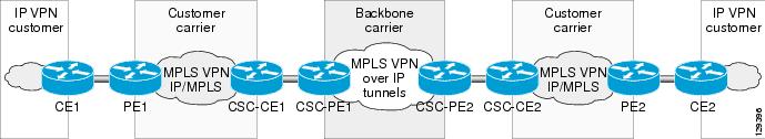
Figure 2 shows how to configure the MPLS VPN Carrier Supporting Carrier over IP Tunnels feature for an MPLS VPN customer carrier to interconnect MPLS/IP networks over a backbone MPLS VPNs over IP Tunnels network.
Figure 2 MPLS VPN Carrier Supporting Carrier over IP Tunnels for an MPLS VPN Customer Carrier
In this example, the following conditions apply:
•
•
•
•
For the MPLS VPN Carrier Supporting Carrier over IP Tunnels configuration shown in Figure 2, you must configure the two PE routers (CSC-PE1 and CSC-PE2) in the backbone carrier network and the two CE routers (CSC-CE1 and CSC-CE2) in the customer carrier networks, as described in the following sections.
CSC-CE1 Configuration
hostname csc-ce1mpls label protocol ldpinterface Loopback0ip address 10.127.100.2 255.255.255.255no ip directed-broadcastno ip route-cacheno ip mroute-cacheinterface Loopback1ip address 10.127.101.2 255.255.255.255no ip directed-broadcastno ip route-cacheinterface Loopback2ip address 10.127.102.2 255.255.255.255no ip directed-broadcastinterface POS2/0no ip addressno ip directed-broadcastencapsulation frame-relayno keepalivetag-switching ipcrc 32clock source internalinterface POS2/0.100 point-to-pointip address 192.168.80.4 255.255.255.0no ip directed-broadcastmpls label protocol ldptag-switching ipframe-relay interface-dlci 100interface POS2/0.200 point-to-pointip address 192.168.80.5 255.255.255.0no ip directed-broadcastmpls bgp forwardingframe-relay interface-dlci 200interface POS2/0.300 point-to-pointip address 192.168.80.6 255.255.255.0no ip directed-broadcastmpls label protocol ldptag-switching ipframe-relay interface-dlci 300interface POS2/0.400 point-to-pointip address 192.168.80.11 255.255.255.0no ip directed-broadcastframe-relay interface-dlci 400interface POS6/3no ip addressno ip directed-broadcastencapsulation frame-relayno keepalivecrc 32clock source internalinterface POS6/3.100 point-to-pointip address 192.168.70.4 255.255.255.0no ip directed-broadcastframe-relay interface-dlci 70interface POS6/3.200 point-to-pointip address 192.168.70.5 255.255.255.0no ip directed-broadcastmpls label protocol ldptag-switching ipframe-relay interface-dlci 200interface POS6/3.300 point-to-pointip address 192.168.70.6 255.255.255.0no ip directed-broadcastframe-relay interface-dlci 300router ospf 16log-adjacency-changesredistribute connected subnetsnetwork 192.168.70.4.0.0.0.255 area 100network 192.168.80.4.0.0 0.255 area 100router ospf 26log-adjacency-changesredistribute connected subnetsredistribute bgp 200 subnetsnetwork 192.168.70.5.0.0.0.255 area 200network 192.168.80.5.0.0.0.255 area 200router ospf 3log-adjacency-changesredistribute connected subnetsnetwork 192.168.70.6.0.0.0.255 area 3network 192.168.80.6.0.0.0.255 area 3network 10.102.2.2 0.0.0.0 area 3router bgp 200bgp log-neighbor-changesneighbor 192.168.80.5.remote-as 100neighbor 10.101.1.1 remote-as 200neighbor 10.101.1.1 update-source Loopback1neighbor 10.201.1.1 remote-as 200neighbor 10.201.1.1 update-source Loopback1neighbor 10.201.2.2 remote-as 200neighbor 10.201.2.2 update-source Loopback1address-family ipv4redistribute ospf 26neighbor 192.168.80.5.activateneighbor 192.168.80.5 send-labelno neighbor 10.101.1.1 activateno neighbor 10.201.1.1 activateno neighbor 10.201.2.2 activateno auto-summaryno synchronizationexit-address-familyaddress-family vpnv4neighbor 10.101.1.1 activateneighbor 10.101.1.1 send-community extendedneighbor 10.201.1.1 activateneighbor 10.201.1.1 send-community extendedneighbor 10.201.2.2 activateneighbor 10.201.2.2 send-community extendedexit-address-familyCSC-PE1 Configuration
hostname csc-pe1ip vrf forwardingip vrf my_rivrd 1:1ip vrf vpn100rd 100:100route-target export 100:100route-target import 100:100ip vrf vpn200rd 200:200route-target export 200:200route-target import 200:200ip vrf vpn300rd 300:300route-target export 300:300route-target import 300:300mpls label protocol ldpinterface Loopback0ip address 10.127.80.80 255.255.255.255no ip directed-broadcastip router isisno ip route-cacheinterface Tunnel100bandwidth 10000ip vrf forwarding my_rivip address 192.168.1.1 255.255.255.255no ip redirectsno ip directed-broadcasttunnel source Loopback0tunnel mode l3vpn l2tpv3 multipointinterface POS4/0no ip addressno ip directed-broadcastencapsulation frame-relayno keepalivempls label protocol ldptag-switching ipcrc 32clock source internalinterface POS4/0.100 point-to-pointip vrf forwarding vpn100ip address 192.168.80.4 255.255.255.0no ip directed-broadcastmpls label protocol ldptag-switching ipframe-relay interface-dlci 100interface POS4/0.200 point-to-pointip vrf forwarding vpn200ip address 192.168.80.5 255.255.255.0no ip directed-broadcastmpls bgp forwardingframe-relay interface-dlci 200interface POS4/0.300 point-to-pointip vrf forwarding vpn300ip address 192.168.80.6 255.255.255.0no ip directed-broadcastmpls label protocol ldptag-switching ipframe-relay interface-dlci 300interface POS5/0ip address 192.168.90.4 255.255.255.0no ip directed-broadcastip router isisno keepalivecrc 32clock source internalrouter ospf 16 vrf vpn100log-adjacency-changesredistribute bgp 100 subnetsnetwork 192.168.80.4.0.0.0.255 area 100router ospf 3 vrf vpn300log-adjacency-changesredistribute bgp 100 subnetsnetwork 192.168.80.6.0.0.0.255 area 3router isisnet 49.0001.0000.0000.000a.00router bgp 100bgp log-neighbor-changesneighbor 10.10.10.10 remote-as 100neighbor 10.10.10.10 update-source Loopback0neighbor 10.20.20.20 remote-as 100neighbor 10.20.20.20 update-source Loopback0neighbor 10.30.30.30 remote-as 100neighbor 10.30.30.30 update-source Loopback0address-family ipv4no neighbor 10.10.10.10 activateno neighbor 10.20.20.20 activateno neighbor 10.30.30.30 activateno auto-summaryno synchronizationexit-address-familyaddress-family ipv4 tunnelneighbor 10.10.10.10 activateneighbor 10.20.20.20 activateneighbor 10.30.30.30 activateexit-address-familyaddress-family vpnv4neighbor 10.10.10.10 activateneighbor 10.10.10.10 send-community bothneighbor 10.10.10.10 route-map rmap1 inneighbor 10.20.20.20 activateneighbor 10.20.20.20 send-community bothneighbor 10.20.20.20 route-map rmap1 inneighbor 10.30.30.30 activateneighbor 10.30.30.30 send-community bothneighbor 10.30.30.30 route-map rmap1 inexit-address-familyaddress-family ipv4 vrf vpn300redistribute connectedredistribute ospf 3 vrf vpn300no auto-summaryno synchronizationexit-address-familyaddress-family ipv4 vrf vpn200neighbor 192.168.80.5.remote-as 200neighbor 192.168.80.5 activateneighbor 192.168.80.5 as-overrideneighbor 192.168.80.5 send-labelno auto-summaryno synchronizationexit-address-familyaddress-family ipv4 vrf vpn100redistribute connectedredistribute ospf 16 vrf vpn100no auto-summaryno synchronizationexit-address-familyaddress-family ipv4 vrf my_rivno auto-summaryno synchronizationexit-address-familyaddress-family ipv4 vrf forwardingno auto-summaryno synchronizationexit-address-familyip route vrf my_riv 0.0.0.0 0.0.0.0 Tunnel100route-map rmap1 permit 10set ip next-hop in-vrf my_rivCSC-CE2 Configuration
hostname csc-ce2interface Loopback0ip address 10.127.200.2 255.255.255.255no ip directed-broadcastno ip route-cacheno ip mroute-cacheinterface Loopback1ip address 10.127.201.2 255.255.255.255no ip directed-broadcastno ip route-cacheno ip mroute-cacheinterface Loopback2ip address 10.127.202.2 255.255.255.255no ip directed-broadcastinterface Loopback3ip address 10.127.203.2 255.255.255.255no ip directed-broadcastinterface Loopback4ip address 10.127.204.2 255.255.255.255no ip directed-broadcastinterface Loopback5ip address 10.127.11.11 255.255.255.255no ip directed-broadcastinterface POS2/0ip address 192.168.110.5 255.255.255.0no ip directed-broadcastno keepalivempls bgp forwardingtag-switching ipcrc 32clock source internalrouter ospf 27log-adjacency-changesredistribute connected subnetsredistribute bgp 200 subnetsnetwork 192.168.110.5.0.0.0.255 area 200network 192.168.120.5.0.0.0.255 area 200network 10.201.2.2 0.0.0.0 area 200router bgp 200bgp log-neighbor-changesneighbor 10.101.1.1 remote-as 200neighbor 10.101.1.1 update-source Loopback1neighbor 10.101.2.2 remote-as 200neighbor 10.101.2.2 update-source Loopback1neighbor 192.168.110.5 remote-as 100neighbor 192.168.110.7 remote-as 100neighbor 10.201.1.1 remote-as 200neighbor 10.201.1.1 update-source Loopback1address-family ipv4redistribute eigrp 27redistribute ospf 27no neighbor 10.101.1.1 activateno neighbor 10.101.2.2 activateneighbor 192.168.110.5 activateneighbor 192.168.110.5 send-labelneighbor 192.168.110.7 activateneighbor 192.168.110.7 send-labelno neighbor 10.201.1.1 activateno auto-summaryno synchronizationexit-address-familyaddress-family vpnv4neighbor 10.101.1.1 activateneighbor 10.101.1.1 send-community extendedneighbor 10.101.2.2 activateneighbor 10.101.2.2 send-community extendedneighbor 10.201.1.1 activateneighbor 10.201.1.1 send-community extendedexit-address-familyaddress-family ipv4 vrf vpn201redistribute connectedno auto-summaryno synchronizationexit-address-familyip classlessip route 192.168.80.8 255.255.255.0 110.8.0.1ip route 192.168.80.11 255.255.255.0 110.11.0.1CSC-PE2 Configuration
hostname csc-pe2-2ip vrf forwardingip vrf my_rivrd 1:1ip vrf vpn200rd 200:200route-target export 200:200route-target import 200:200interface Loopback0ip address 10.127.20.20 255.255.255.255no ip directed-broadcastip router isisno ip route-cacheno ip mroute-cacheinterface Tunnel100bandwidth 10000ip vrf forwarding my_rivip address 192.168.5.5 255.255.255.255no ip redirectsno ip directed-broadcasttunnel source Loopback0tunnel mode l3vpn l2tpv3 multipointinterface POS3/0ip vrf forwarding vpn200ip address 192.168.110.5 255.255.255.0no ip directed-broadcastno keepalivempls bgp forwardingcrc 32clock source internalinterface POS6/0ip address 192.168.100.5 255.255.255.0no ip directed-broadcastip router isiscrc 32clock source internalrouter isisnet 49.0001.0000.0000.000d.00router bgp 100bgp log-neighbor-changesneighbor 10.127.80.80 remote-as 100neighbor 10.127.80.80 update-source Loopback0address-family ipv4no neighbor 10.127.80.80 activateno auto-summaryno synchronizationexit-address-familyaddress-family ipv4 tunnelneighbor 10.127.80.80 activateexit-address-familyaddress-family vpnv4neighbor 10.127.80.80 activateneighbor 10.127.80.80 send-community bothneighbor 10.127.80.80 route-map rmap1 inexit-address-familyaddress-family ipv4 vrf vpn400redistribute connectedno auto-summaryno synchronizationexit-address-familyaddress-family ipv4 vrf vpn200neighbor 192.168.110.5 remote-as 200neighbor 192.168.110.5 activateneighbor 192.168.110.5 as-overrideneighbor 192.168.110.5 send-labelneighbor 192.168.110.7 remote-as 200neighbor 192.168.110.7 activateneighbor 192.168.110.7 as-overrideneighbor 192.168.110.7 send-labelno auto-summaryno synchronizationexit-address-familyaddress-family ipv4 vrf my_rivno auto-summaryno synchronizationexit-address-familyaddress-family ipv4 vrf forwardingno auto-summaryno synchronizationexit-address-familyip route vrf my_riv 0.0.0.0 0.0.0.0 Tunnel100Verifying the VRF—Example
Use the show ip bgp vpnv4, show ip route vrf, and show ip cef vrf commands to verify that VRF and RiV are configured correctly propagating to the appropriate routing and forwarding tables.
Verify that the specified VRF prefix has been received by BGP. The BGP table entry should show that the route-map has worked and that the next hop is showing in the RiV. Use the show ip bgp vpnv4 command as shown in this example:
Router# show ip bgp vpnv4 vrf vrf-name 10.10.10.4BGP routing table entry for 100:1:10.10.10.4/24, version 12Paths: (1 available, best #1)Not advertised to any peerLocal172.16.1.2 in "vrf-name" from 172.16.1.2 (172.16.1.2)Origin incomplete, metric 0, localpref 100, valid, internal, bestExtended Community: RT:100:1Use the show ip route vrf command to confirm that the same information has been propagated to the routing table:
Router# show ip route vrf vrf-name 10.10.10.4Routing entry for 10.10.10.4/24Known via "bgp 100", distance 200, metric 0, type internalLast update from 172.16.1.2 00:23:07 agoRouting Descriptor Blocks:* 172.16.1.2 (vrf-name), from 172.16.1.2, 00:23:07 agoRoute metric is 0, traffic share count is 1AS Hops 0
Use the show ip cef vrf command to verify that the same information has been propagated to the CEF forwarding table:
Router# show ip cef vrf vrf-namePrefix Next Hop Interface0.0.0.0/0 attached Tunnel10.0.0.0/32 receive10.10.10.4/32 10.10.10.4 Tunnel1172.16.1.2/32 receive224.0.0.0/4 drop224.0.0.0/24 receive255.255.255.255/32 receiveRouter# show ip cef vrf CUSTOMER_APrefix Next Hop Interface0.0.0.0/0 drop Null0 (default route handler entry)0.0.0.0/32 receive192.168.0.0/8 10.10.10.4 Tunnel110.0.4.0/24 10.10.10.4 Tunnel110.0.6.0/24 attached Serial2/010.0.6.0/32 receive10.0.6.1/32 receive10.0.6.255/32 receive224.0.0.0/4 drop224.0.0.0/24 receive255.255.255.255/32 receiveVerifying the Multipoint L2TPv3 Tunnel—Examples
Use the show interface, show l2tun, and show tunnel endpoint commands to verify the configuration of the, tunnel interface, L2TPv3 tunnel and tunnel endpoints.
Use the show interface command, as show in the display, to verify that the tunnel interface is up and configured correctly:
Router# show interface Tunnel 1Tunnel1 is up, line protocol is upHardware is TunnelInternet address is 172.16.1.2/32MTU 1514 bytes, BW 9 Kbit, DLY 500000 usec, rely 255/255, load 1/255Encapsulation TUNNEL, loopback not setKeepalive not setTunnel source 10.10.10.6 (Loopback0)Tunnel protocol/transport Multi-L2TPv3 (L3VPN), sequencing disabledTransporting l3vpn traffic to routes recursing through "MY_RIV"Key disabledChecksumming of packets disabled, fast tunneling enabledLast input never, output never, output hang neverLast clearing of "show interface" counters neverInput queue: 0/75/0/0 (size/max/drops/flushes); Total output drops: 0Queueing strategy: fifoOutput queue: 0/0 (size/max)5 minute input rate 0 bits/sec, 0 packets/sec5 minute output rate 0 bits/sec, 0 packets/sec0 packets input, 0 bytes, 0 no bufferReceived 0 broadcasts, 0 runts, 0 giants, 0 throttles0 input errors, 0 CRC, 0 frame, 0 overrun, 0 ignored, 0 abort0 packets output, 0 bytes, 0 underruns0 output errors, 0 collisions, 0 interface resets0 output buffer failures, 0 output buffers swapped outUse the show l2tun command, as shown in the display, to verify tunnel and session information:
Router# show l2tunTunnel and Session Information Total tunnels 0 sessions 1L3VPN Session Information Total sessions 1LocID Cookie1025 0xC0DEE550DEADBEEFUse the show tunnel endpoint command, as shown in the display to verify that the tunnel endpoints were created correctly:
Router# show tunnel endpointTunnel1 running in Multi-L2TPv3 (L3VPN) modeRFC2547/L3VPN Tunnel endpoint discovery is active on Tu1Transporting l3vpn traffic to all routes recursing through "MY_RIV"Endpoint 10.10.10.4 via destination 10.10.10.4Use the show ip bgp ipv4 tunnel command, as shown in the display to verify tunnel specific information configured under the "tunnel" SAFI:
Router# show ip bgp ipv4 tunnelBGP table version is 3, local router ID is 10.3.3.3Status codes: s suppressed, d damped, h history, * valid, > best, i - internal,r RIB-failure, S StaleOrigin codes: i - IGP, e - EGP, ? - incompleteNetwork Next Hop Metric LocPrf Weight Path*> 10.3.3.3/32 0.0.0.0 0 32768 ?*>i10.5.5.5/32 10.5.5.5 0 100 0 ?ssacount=1, type L2TP, len 16pref 0,flags 0,cookielen 8,ss_id 402,cookie_high D0338947,cookie_low 69DCF79Essacount=1, type L2TP, len 16pref 0,flags 0,cookielen 8,ss_id 401,cookie_high 6FB30F92,cookie_low A7E61105Verifying QoS Configuration—Example
This section contains sample output from the show policy-map interface command and the show policy-map command. The output from these commands can be used to verify and monitor the feature configuration in your network.
The following is sample output from the show policy-map interface command. In this sample output, the character string "set precedence tunnel 6" indicates that the tunnel marking has been configured to set the IP precedence in the header of tunneled packets.
Router# show policy-map interfacePOS0/0.1Service-policy input: tunnel (1196)Class-map: frde (match-any) (1197/18)0 packets, 0 bytes5 minute offered rate 0 bps, drop rate 0 bpsMatch: fr-de (1198)Set Policy:set precedence tunnel 6Class-map: class-default (match-any) (1200/0)0 packets, 0 bytes5 minute offered rate 0 bps, drop rate 0 bpsMatch: any (1201)Set Policy:set precedence tunnel 3The following is sample output from the show policy-map command. In this sample output, the character string "ip precedence tunnel 4" indicates that the tunnel marking on L2TPv3 feature has been configured to set the IP precedence in the header of an L2TPv3 tunneled packet.
Router# show policy-mapPolicy Map TUNNEL_MARKINGClass MATCH_FRDEset ip precedence tunnel 4
Verifying MPLS VPN Carrier Supporting Carrier over IP Tunnels—Example
This section shows how to use the show mpls ldp discovery command to display the status of the label distribution protocol (LDP) sessions between a PE router in the backbone-carrier (MPLS VPNs over IP Tunnels) network and the CE router in a customer carrier network.
The following example shows the LDP sessions in VRF Customer A of the PE router of the backbone carrier.
Router# show mpls ldp discovery vrf customer_aLocal LDP Identifier:139.0.0.0:0Discovery Sources:Interfaces:Ethernet1/0 (ldp): xmit/recvLDP Id: 55.0.0.1:0POS6/0 (ldp): xmitThe next example shows how to display all LDP sessions that are active on the router.
Router# show mpls ldp discovery allLocal LDP Identifier:141.141.141.141:0Discovery Sources:Interfaces:Ethernet1/5 (ldp): xmit/recvLDP Id: 5.5.5.5:0VRF vpn1: Local LDP Identifier:139.0.0.1:0Discovery Sources:Interfaces:Ethernet1/0 (ldp): xmit/recvLDP Id: 55.0.0.1:0POS6/0 (ldp): xmit Local LDP Identifier:The Local LDP Identifier field shows the LDP identifier for the local label switching router for this session. The Interfaces field displays the interfaces configured for the Carrier Supporting Carrier feature that are performing LDP discovery activity:
•
•
Additional References
For additional information related to this feature, refer to the following references:
Related Documents
CEF switching
Cisco IOS Switching Services Configuration Guide, Release 12.3
QoS—Tunnel Marking
VPN configuration
Cisco IOS Dial Services Configuration Guide, Release 12.3 and Cisco IOS Switching Services Configuration Guide, Release 12.3
VPN Routing and Forwarding (VRF) instances
Cisco IOS Switching Services Configuration Guide, Release 12.3
Globally configuring the Label Distribution Protocol (LDP) on every interface associated with a specified Interior Gateway Protocol (IGP) instance
Configuring PE routers in an MPLS VPN-based service provider to allow other service providers to use a segment of its backbone network:
•
•
MPLS VPN—Carrier Supporting Carrier
MPLS VPN—Carrier Supporting Carrier—IPv4 BGP Label Distribution
Standards
IPv4-Tunnel SAFI
IPv4-Tunnel SAFI
http://www.ietf.org/internet-drafts/draft-nalawade-kapoor-tunnel-safi-02.txt
MIBs
RFCs
Technical Assistance
Command Reference
This section documents modified commands.
address-family ipv4—BGP
To enter address family configuration mode to configure an IPv4 routing session under a BGP routing process, use the address-family ipv4 command in router configuration mode. To disable an address family specific IPv4 routing session, use the no form of this command.
address-family ipv4 [multicast | unicast | vrf vrf-name | tunnel]
no address-family ipv4 [multicast | unicast | vrf vrf-name | tunnel]
Syntax Description
Defaults
IP Version 4 address prefixes are not enabled. Unicast address prefixes are the default when IP Version 4 address prefixes are configured.
Command Modes
Router configuration
Command History
Usage Guidelines
The address-family ipv4 command places the router in an address family configuration mode, from which you can configure address family and subaddress family specific routing sessions that use standard IP Version 4 address prefixes. To leave an address family configuration mode and return to router configuration mode, type exit.
Routing information for address family IP Version 4 is advertised by default when you configure a BGP routing session using the neighbor remote-as command unless you enter the no bgp default ipv4-unicast command.
The tunnel keyword is used to enable the tunnel subaddress family identifier (SAFI) under the IPv4 address family identifier. This SAFI is used to advertise the tunnel endpoints and the SAFI specific attributes (which contain the tunnel type and tunnel capabilities). Redistribution of tunnel endpoints into the BGP IPv4 tunnel SAFI table occurs automatically when the tunnel address-family is configured. However, peers need to be activated under the tunnel address-family before the sessions can exchange tunnel information.
Examples
The following example places the router in tunnel address family configuration mode:
Router(config)# router bgp 100Router(config-router)# address-family ipv4 tunnelRouter(config-router-af)#The following example places the router in IPv4 address family configuration mode:
Router(config)# router bgp 100Router(config-router)# address-family ipv4Router(config-router-af)#The following example places the router in IPv4 multicast address family configuration mode:
Router(config)# router bgp 100Router(config-router)# address-family ipv4 multicastRouter(config-router-af)#The following example places the router in IPv4 unicast address family configuration mode:
Router(config)# router bgp 100Router(config-router)# address-family ipv4 unicastRouter(config-router-af)#The following example places the router in address family configuration mode and specifies cisco as the name of the VRF instance to associate with subsequent IP Version 4 address family configuration mode commands:
Router(config)# router bgp 100Router(config-router)# address-family ipv4 vrf ciscoRouter(config-router-af)#
Note
Related Commands
clear ip bgp
To reset a BGP connection using BGP soft reconfiguration, use the clear ip bgp command in privileged EXEC mode.
clear ip bgp {* | neighbor-address | peer-group peer-group-name} [ipv4 tunnel] [soft [in | out]]
Syntax Description
Defaults
No reset is initiated.
Command Modes
Privileged EXEC
Command History
10.0
This command was introduced.
12.0(6)T
12.0(2)S
The dynamic inbound soft reset capability was added.
Usage Guidelines
You can reset inbound routing table updates dynamically or by generating new updates using stored update information. Using stored update information required additional memory for storing the updates.
To reset inbound routing table updates dynamically, all BGP routers must support the route refresh capability. To determine whether a BGP router supports this capability, use the show ip bgp neighbors command. If a router supports the route refresh capability, the following message is displayed:
Received route refresh capability from peer.If all BGP routers support the route refresh capability, use the clear ip bgp {* | address | peer-group-name} in command. You need not use the soft keyword, because soft reset is automatically assumed when the route refresh capability is supported.
To generate new inbound updates from stored update information (rather than dynamically) without resetting the BGP session, you must preconfigure the local BGP router using the neighbor soft-reconfiguration inbound command. This preconfiguration causes the software to store all received updates without modification regardless of whether an update is accepted by the inbound policy. Storing updates is memory intensive and should be avoided if possible.
Outbound BGP soft configuration has no memory overhead and does not require any preconfiguration. You can trigger an outbound reconfiguration on the other side of the BGP session to make the new inbound policy take effect.
Use this command whenever any of the following changes occur:
•
•
•
•
Examples
The following example clears the inbound session with the neighbor 10.108.1.1 without resetting the session:
Router# clear ip bgp 10.108.1.1 soft inThe following example clears the outbound session with the peer group named corp without resetting the session:
Router# clear ip bgp peer-group corp soft outRelated Commands
neighbor soft-reconfiguration
Configures the Cisco IOS software to start storing updates.
show ip bgp
Displays entries in the BGP routing table.
clear tunnel l3vpn l2tpv3
To reset a Layer 3 VPN session over a L2TPv3 tunnel, use the clear tunnel l3vpn l2tpv3 command in privileged EXEC mode.
clear tunnel l3vpn l2tpv3 [hold-time]
Syntax Description
Defaults
No reset is initiated.
Command Modes
Privileged EXEC
Command History
12.0(28)S
This command was integrated in Cisco IOS Release 12.0(28)S.
12.0(30)S
Support for the Cisco 12000 series Internet router was added.
Usage Guidelines
This command is used to generate and distribute a new L2TPv3 session for a Layer 3 VPN. This command is issued on the PE router. The hold-time argument is used to configure the amount of time that the existing session will remain valid, while the new session is propagated to peers. The default value for the hold-time argument is 15 seconds. This should be enough time for most networks. However, this value can be increased if it takes longer for the new session to propagate to all other PE routers.
Examples
The following example resets the existing L2TPv3 session for a Layer 3 VPN and generates a new session:
Router# clear tunnel l3vpn l2tpv3show ip bgp ipv4
To display entries in the IP version 4 (IPv4) Border Gateway Protocol (BGP) routing table, use the show ip bgp ipv4 command in EXEC mode.
show ip bgp ipv4 {multicast | unicast | tunnel [ip-address | summary]}
Syntax Description
Command Modes
EXEC
Command History
Examples
The following is sample output from the show ip bgp ipv4 unicast command:
Router# show ip bgp ipv4 unicastBGP table version is 4, local router ID is 10.0.40.1Status codes: s suppressed, d damped, h history, * valid, > best, i - internalOrigin codes: i - IGP, e - EGP, ? - incompleteNetwork Next Hop Metric LocPrf Weight Path*> 10.10.10.0/24 172.16.10.1 0 0 300 i*> 10.10.20.0/24 172.16.10.1 0 0 300 i* 10.20.10.0/24 172.16.10.1 0 0 300 iThe following is sample output from the show ip bgp ipv4 multicast command:
Router# show ip bgp ipv4 multicastBGP table version is 4, local router ID is 10.0.40.1Status codes: s suppressed, d damped, h history, * valid, > best, i - internalOrigin codes: i - IGP, e - EGP, ? - incompleteNetwork Next Hop Metric LocPrf Weight Path*> 10.10.10.0/24 172.16.10.1 0 0 300 i*> 10.10.20.0/24 172.16.10.1 0 0 300 i* 10.20.10.0/24 172.16.10.1 0 0 300 iThe following is sample output from the show ip bgp ipv4 tunnel command:
Router# show ip bgp ipv4 tunnelBGP table version is 3, local router ID is 10.3.3.3Status codes: s suppressed, d damped, h history, * valid, > best, i - internal,r RIB-failure, S StaleOrigin codes: i - IGP, e - EGP, ? - incompleteNetwork Next Hop Metric LocPrf Weight Path*> 10.3.3.3/32 0.0.0.0 0 32768 ?*>i10.5.5.5/32 10.5.5.5 0 100 0 ?ssacount=1, type L2TP, len 16pref 0,flags 0,cookielen 8,ss_id 402,cookie_high D0338947,cookie_low 69DCF79Essacount=1, type L2TP, len 16pref 0,flags 0,cookielen 8,ss_id 401,cookie_high 6FB30F92,cookie_low A7E61105The following is sample output from the show ip bgp ipv4 summary command:
Router# show ip bgp ipv4 tunnel summaryBGP router identifier 10.3.3.3, local AS number 1BGP table version is 3, main routing table version 3..2 BGP SAFI-Specific-Attr entries using 80 bytes of memory..Neighbor V AS MsgRcvd MsgSent TblVer InQ OutQ Up/Down State/PfxRcd10.5.5.5 4 1 422 413 3 0 0 05:28:23 1The following is sample output from the show ip bgp tunnel command when a single IP address is specified:
Router# show ip bgp ip tunnel 10.5.5.5BGP routing table entry for 10.5.5.5/32, version 2Paths: (1 available, best #1, table IPv4-Tunnel-BGP-Table)Not advertised to any peerLocal10.5.5.5 (metric 30) from 10.5.5.5 (10.5.5.5)Origin incomplete, metric 0, localpref 100, valid, internal, bestSAFI Specific Attribute: ssacount=1, type L2TP, len 16pref 0,flags 0,cookielen 8,ss_id 402,cookie_high D0338947,cookie_low 69DCF79ETable 3 describes the significant fields shown in the display.
Related Commands
Copyright © 2006 Cisco Systems, Inc. All rights reserved