Downloads |
 Feedback Feedback
|
Table Of Contents
Prerequisites for Any Transport over MPLS
Cisco 7200 and 7500 Series Routers: Required Chassis, Processors, and VIPs
Cisco 7200 and 7500 Series Routers: Supported Port Adapters
Cisco 12000 Series Routers: Supported Line Cards
Restrictions for Any Transport over MPLS
ATM AAL5 over MPLS Restrictions
ATM Cell Relay over MPLS Restrictions
Ethernet over MPLS Restrictions
Frame Relay over MPLS Restrictions
Restrictions Specific to the Cisco 12000 Series Routers
Information about Any Transport over MPLS
How AToM Transports Layer 2 Packets
Compatibility with Previous Releases of AToM
How to Configure Any Transport over MPLS
How to Configure the Pseudowire-Class
How to Configure ATM AAL5 over MPLS
Configuring OAM Cell Emulation for ATM AAL5 over MPLS
How to Configure ATM Cell Relay over MPLS
Varieties of ATM Cell Relay over MPLS
Configuring ATM Cell Relay over MPLS: VC Mode
Configuring ATM Cell Relay over MPLS: VP Mode
Configuring ATM Cell Relay over MPLS: Port Mode
Configuring ATM Cell Relay over MPLS: Single Cell Relay
Configuring ATM Cell Relay over MPLS: Packed Cell Relay
OAM Support with ATM Cell Relay over MPLS
How to Configure Ethernet over MPLS
Configuring Ethernet over MPLS: VLAN Mode
Configuring Ethernet over MPLS: Port Mode
Configuring Ethernet over MPLS: VLAN ID Rewrite
How to Configure Frame Relay over MPLS
How Frame Relay PDUs Move Between PE Routers
Configuring Frame Relay over MPLS with DLCI-to-DLCI Connections
Configuring Frame Relay over MPLS with Port-to-Port Connections
Enabling Other PE Devices to Transport Frame Relay Packets
Local Management Interface and Frame Relay over MPLS
How to Configure HDLC and PPP over MPLS
Configuring HDLC and PPP over MPLS
How to Configure Distributed CEF Mode
How to Configure MPLS Traffic Engineering Fast Reroute
Configuring MPLS TE Fast Reroute
Fast Reroute Configuration Example
How to Configure Tunnel Selection
Tunnel Selection Configuration Guidelines
Tunnel Selection Configuration Example
Troubleshooting Tunnel Selection
How to Estimate the Size of Packets Traveling Through the Core Network
Example of Estimating Packet Size
Changing the MTU Size on the P and PE Routers
How To Configure QOS with AToM
How to Set Experimental Bits with AToM
ATM AAL5 over MPLS and EXP Bits
ATM Cell Relay over MPLS and EXP Bits
Ethernet over MPLS and EXP Bits
Frame Relay over MPLS and EXP Bits
HDLC over MPLS and PPP over MPLS and EXP Bits
Using 802.1Q P Bits to Determine the Experimental Bit Settings
How to Configure QOS Features with the Cisco 12000 Series Routers
Configuring Traffic Policing with the Cisco 12000 Series Routers
Configuring Traffic Policing for ATM AAL5 and ATM Cell Relay on the Cisco 12000 Series Routers
Configuring Traffic Policing for Frame Relay on the Cisco 12000 Series Routers
How to Configure QoS Features with the Cisco 7500 Series Routers
Setting the Frame Relay Discard Eligibility Bit on the Cisco 7500 Series Routers
Matching the Frame Relay Discard Eligibility Bit on the Cisco 7500 Series Routers
debug mpls l2transport fast-reroute
Any Transport over MPLS
Any Transport over MPLS (AToM) transports Layer 2 packets over a Multiprotocol Label Switching (MPLS) backbone. AToM enables service providers to connect customer sites with existing data link layer (Layer 2) networks, by using a single, integrated, packet-based network infrastructure — a Cisco MPLS network. Instead of separate networks with network management environments, service providers can deliver Layer 2 connections over an MPLS backbone. AToM provides a common framework to encapsulate and transport supported Layer 2 traffic types over an MPLS network core. AToM supports the following transport types:
•
ATM AAL5 over MPLS
•
•
•
•
•
Feature Specifications for Any Transport over MPLS
12.0(10)ST
Any Transport over MPLS: ATM AAL5 over MPLS was introduced on the Cisco 12000 series routers.
12.1(8a)E
Any Transport over MPLS: Ethernet over MPLS was introduced on the Cisco 7600 series Internet router.
12.0(21)ST
Ethernet over MPLS was introduced on the Cisco 12000 series routers. ATM AAL5 over MPLS was updated.
12.0(22)S
Ethernet over MPLS was integrated into this release. Support for the Cisco 10720 router was added. ATM AAL5 over MPLS was integrated into this release for the Cisco 12000 series routers.
12.0(23)S
The following new features were introduced:
•
•
•
•
These features were supported on the Cisco 7200 and 7500 series routers.
The Cisco 12000, 7200, and 7500 series routers supported the following features:
•
•
The Cisco 10720 Internet router continued support for Ethernet over MPLS.
12.2(14)S
This feature was integrated into Cisco IOS Release 12.2(14)S.
12.2(15)T
This feature was integrated into Cisco IOS Release 12.2(15)T.
12.0(25)S
The following new features were introduced:
•
•
•
•
•
•
•
•
•
•
Cisco 7200 series, Cisco 7500 series, Cisco 12000 series, Cisco 10720 Internet router
See the sections that describe the features to determine the platforms that support the features.
See Prerequisites for Any Transport over MPLS for the supported port adapters and line cards.
Finding Support Information for Platforms and Cisco IOS Software Images
Use Cisco Feature Navigator to find information about platform support and Cisco IOS software image support. Access Cisco Feature Navigator at http://www.cisco.com/go/fn. You must have an account on Cisco.com. If you do not have an account or have forgotten your username or password, click Cancel at the login dialog box and follow the instructions that appear.
Contents
•
•
•
•
Prerequisites for Any Transport over MPLS
On the provider edge (PE) routers, AToM requires the hardware specified in the following sections:
•
•
•
Cisco 7200 and 7500 Series Routers: Required Chassis, Processors, and VIPs
•
–
–
•
–
–
–
Note
Cisco 7200 and 7500 Series Routers: Supported Port Adapters
The following port adapters are supported for the Cisco 7200 and 7500 series routers for each transport type in Cisco IOS Release 12.0(25)S.
Cisco 12000 Series Routers: Supported Line Cards
The following line cards are supported for the Cisco 12000 series routers for each transport type.
Restrictions for Any Transport over MPLS
The following general restrictions pertain to all transport types under AToM:
•
•
ATM AAL5 over MPLS Restrictions
The following restrictions pertain to the ATM AAL5 over MPLS feature:
•
•
ATM Cell Relay over MPLS Restrictions
The following restrictions pertain to the ATM Cell Relay over MPLS feature:
•
Ethernet over MPLS Restrictions
The following restrictions pertain to the Ethernet over MPLS feature:
•
Frame Relay over MPLS Restrictions
The following restrictions pertain to the Frame Relay over MPLS feature:
•
HDLC over MPLS Restrictions
The following restrictions pertain to the HDLC over MPLS feature:
•
•
PPP over MPLS Restrictions
The following restrictions pertain to the PPP over MPLS feature:
•
•
•
•
Restrictions Specific to the Cisco 12000 Series Routers
Fast Reroute
Fast Reroute uses three or more labels, depending on where the Traffic Engineering (TE) tunnel ends:
•
•
The Engine 0 ATM line cards support three or more labels, although performance degrades. The Engine 2 Gigabit Ethernet line cards and IP Service Engine (ISE) line cards support three or more labels and can work with the Fast Reroute feature.
Frame Relay over MPLS
If you configure Frame Relay over MPLS and the core-facing interface is an Engine 4 or 4+ line card and the edge facing interface is an Engine 0 or 2 line card, then the FECN, BECN, CR, and DE bit information is stripped from the PVC.
ATM Cell Relay over MPLS
If you configure the Engine 2 8-Port OC-3 STM-1 ATM line card for ATM single cell relay over MPLS, you cannot configure other Layer 3 features on those ports reserved for ATM cell relay over MPLS.
Information about Any Transport over MPLS
To configure AToM, you must understand the following concepts:
•
•
How AToM Transports Layer 2 Packets
AToM encapsulates Layer 2 frames at the ingress PE and sends them to a corresponding PE at the other end of a pseudowire, which is a connection between the two PE routers. The egress PE removes the encapsulation and sends out the Layer 2 frame.
The successful transmission of the Layer 2 frames between PE routers is due to the configuration of the PE routers. You set up the connection, called a pseudowire, between the routers. You specify the following information on each PE router:
•
•
•
The following example shows the basic configuration steps on a PE router that enable the transport of Layer 2 packets. Each transport type has slightly different steps.
Step 1 defines the interface or subinterface on the PE router.
Router# interface interface-type interface-numberStep 2 specifies the encapsulation type for the interface, such as dot1q.
Router(config-if)# encapsulation encapsulation-typeStep 3 does the following:
•
•
The combination of the peer-router-id and the VC ID must be a unique combination on the router. Two circuits cannot use the same combination of peer-router-id and VC ID.
•
Router(config-if)# xconnect peer-router-id vcid encapsulation mplsAs an alternative, you can set up a pseudowire class to specify the tunneling method and other characteristics. See the "How to Configure the Pseudowire-Class" section for more information.
Compatibility with Previous Releases of AToM
In previous releases of AToM, the command used to configure AToM circuits was mpls l2 transport route. This command has been replaced with the xconnect command.
No new CLI enhancements will be made to the mpls l2transport route command. CLI enhancements will be made to either the xconnect command or pseudowire-class command. Therefore, we recommend that you use the xconnect command to configure AToM circuits.
Configurations from previous releases that use the mpls l2transport route command are still supported.
Benefits of AToM
The following list explains some of the benefits of enabling Layer 2 packets to be sent in the MPLS network:
•
•
•
How to Configure Any Transport over MPLS
This section explains how to perform a basic AToM configuration and includes the following procedures:
•
•
•
•
•
•
•
•
•
•
Prerequisites
Before configuring AToM, ensure that the network is configured as follows:
•
•
•
•
How to Configure the Pseudowire-Class
The successful transmission of the Layer 2 frames between PE routers is due to the configuration of the PE routers. You set up the connection, called a pseudowire, between the routers.
Note
The pseudowire-class configuration group specifies the characteristics of the tunneling mechanism, including:
•
•
•
For more information about the pseudowire-class command, see the feature module Layer 2 Tunnel Protocol Version 3 at the following location:
http://www.cisco.com/univercd/cc/td/doc/product/software/ios120/120newft/120limit/120s/120s24/l2tpv3.htm
Once you specify the encapsulation mpls command, you cannot remove it using the no encapsulation mpls command. Nor can you change the command's setting using the encapsulation l2tpv3 command. Those methods result in the following error message:
Encapsulation changes are not allowed on an existing pw-class.To remove the command, you must delete the pseudowire with the no pseudowire-class command. To change the type of encapsulation, remove the pseudowire with the no pseudowire-class command and re-establish the pseudowire and specify the new encapsulation type.
SUMMARY STEPS
1.
2.
3.
4.
DETAILED STEPS
Configuration Guidelines
You must specify encapsulation mpls as part of the xconnect command or as part of a pseudowire class for the AToM VCs to work properly. If you omit encapsulation mpls as part of the xconnect command, you receive the following error:
% Incomplete command.How to Configure ATM AAL5 over MPLS
ATM AAL5 over MPLS encapsulates ATM AAL5 SDUs in MPLS packets and forwards them across the MPLS network. Each ATM AAL5 SDU is transported as a single packet. Perform this task to enable ATM AAL5 over MPLS.
SUMMARY STEPS
1.
2.
3.
4.
5.
6.
DETAILED STEPS
Configuring OAM Cell Emulation for ATM AAL5 over MPLS
Supported Platforms:
•
•
•
Overview of OAM Cell Emulation
If a PE router does not support the transport of OAM cells across an LSP, you can use OAM cell emulation to locally terminate or loopback the OAM cells. You configure OAM cell emulation on both PE routers, which emulates a VC by forming two unidirectional LSPs. You use the oam-ac emulation-enable command and the oam-pvc manage command on both PE routers to enable OAM cell emulation.
After you enable OAM cell emulation on a router, you can configure and manage the ATM VC in the same manner as you would a terminated VC. A VC that has been configured with OAM cell emulation can send loopback cells at configured intervals toward the local CE router. The endpoint can be either of the following:
•
•
The OAM cells include the following:
•
•
These cells identify and report defects along a VC. When a physical link or interface failure occurs, intermediate nodes insert OAM AIS cells into all the downstream devices affected by the failure. When a router receives an AIS cell, it marks the ATM VC down and sends an RDI cell to let the remote end know about the failure.
Enabling OAM Cell Emulation for ATM AAL5 over MPLS
To enable OAM cell emulation on the PE routers, issue the oam-ac emulation-enable and oam-pvc manage commands in AToM VC configuration mode.
Specifying the Rate at Which AIS Cells Are Sent
The oam-ac emulation-enable command lets you specify the rate at which AIS cells are sent. The default is one cell every second. The range is 0 to 60 seconds.
Configuration Examples for OAM Cell Emulation
The following example enables OAM cell emulation on an ATM PVC:
Router# interface ATM 1/0/0Router(config-if)# pvc 1/200 l2transport
Router(config-atm-vc)# oam-ac emulation-enableRouter(config-atm-vc)# oam-pvc manageThe following example sets the rate at which an AIS cell is sent to every 30 seconds:
Router# interface ATM 1/0/0Router(config-if)# pvc 1/200 l2transport
Router(config-atm-vc)# oam-ac emulation-enable 30Router(config-atm-vc)# oam-pvc manageVerifying OAM Cell Emulation
The following show atm pvc command shows that OAM cell emulation is enabled and working on the ATM PVC:
Router# show atm pvc 5/500ATM4/1/0.200: VCD: 6, VPI: 5, VCI: 500UBR, PeakRate: 1AAL5-LLC/SNAP, etype:0x0, Flags: 0x34000C20, VCmode: 0x0OAM Cell Emulation: enabled, F5 End2end AIS Xmit frequency: 1 second(s)OAM frequency: 0 second(s), OAM retry frequency: 1 second(s)OAM up retry count: 3, OAM down retry count: 5OAM Loopback status: OAM DisabledOAM VC state: Not ManagedVerifiedILMI VC state: Not ManagedInPkts: 564, OutPkts: 560, InBytes: 19792, OutBytes: 19680InPRoc: 0, OutPRoc: 0InFast: 4, OutFast: 0, InAS: 560, OutAS: 560InPktDrops: 0, OutPktDrops: 0CrcErrors: 0, SarTimeOuts: 0, OverSizedSDUs: 0Out CLP=1 Pkts: 0OAM cells received: 26F5 InEndloop: 0, F5 InSegloop: 0, F5 InAIS: 0, F5 InRDI: 26OAM cells sent: 77F5 OutEndloop: 0, F5 OutSegloop: 0, F5 OutAIS: 77, F5 OutRDI: 0OAM cell drops: 0Status: UPHow to Configure ATM Cell Relay over MPLS
This section contains the following concepts and procedures:
•
•
•
•
•
•
Varieties of ATM Cell Relay over MPLS
ATM cell relay over MPLS provides several configuration options:
•
•
•
•
•
Table 1 shows the platforms that support the new ATM cell relay features. The following sections explain how to configure each feature.
Note
Configuring ATM Relay over MPLS with the Cisco 12000 Series Router Engine 2 8-Port OC-3 STM-1 ATM Line Card
If you configure ATM cell relay on the Cisco 12000 series router with an engine 2 8-port OC-3 STM-1 ATM line card, note the following configuration differences:
•
•
–
–
–
–
If you configured the Engine 2 8-port OC-3 STM-1 ATM line card on a port for ATM AAL5 over MPLS and you now want to configure ATM cell relay over MPLS on that port, the VCs for AAL5 on that port and its corresponding port are removed. The same is also true if you have ATM AAL5 UNI terminated VCs or ATM Cell Relay over MPLS VCs. You receive the following messages:
All VCs/VPs on interface 15/7 and 15/6 will be deleted. Continue ? [yes/no]:SLOT 15:00:28:20: %PM622-6-SAR_MODE_CHANGED: port 7 and 6 switched to aal0 mode•
Configuring ATM Cell Relay over MPLS: VC Mode
Supported Platforms:
•
•
•
Perform this task to configure ATM Cell Relay on the permanent virtual circuits.
SUMMARY STEPS
1.
2.
3.
4.
5.
6.
DETAILED STEPS
VC Mode Configuration Example
Example 1 shows the configuration for carrying single ATM cells over PVCs.
Verifying ATM Cell Relay VC Mode
The following show atm vc command shows that the interface is configured for VC mode cell relay:
Router# show atm vc 7ATM3/0: VCD: 7, VPI: 23, VCI: 100UBR, PeakRate: 149760AAL0-Cell Relay, etype:0x10, Flags: 0x10000C2D, VCmode: 0x0OAM Cell Emulation: not configuredInBytes: 0, OutBytes: 0Status: UPConfiguring ATM Cell Relay over MPLS: VP Mode
Supported Platforms:
•
•
•
Virtual Path (VP) mode allows cells coming into a predefined permanent virtual path (PVP) on the ATM interface to be transported over the MPLS backbone to a predefined PVP on the egress ATM interface. You can use VP mode to send single cells or packed cells over the MPLS backbone.
To configure VP mode, you must specify the following:
•
•
Perform this task to transport ATM cells over a PVP.
SUMMARY STEPS
1.
2.
3.
4.
5.
DETAILED STEPS
VP Mode Configuration Guidelines
When configuring ATM Cell Relay over MPLS in VP mode, use the following guidelines:
•
•
•
•
•
•
•
VP Mode Configuration Example
The following example transports single ATM cells over a virtual path:
pseudowire-class vp-cell-relayencapsulation mplsint atm 5/0atm pvp 1 l2transportxconnect 10.0.0.1 123 pw-class vp-cell-relayVerifying ATM Cell Relay VP Mode
The following show atm vp command shows that the interface is configured for VP mode cell relay:
Router# show atm vp 1ATM5/0 VPI: 1, Cell Relay, PeakRate: 149760, CesRate: 0, DataVCs: 1, CesVCs: 0, Status: ACTIVEVCD VCI Type InPkts OutPkts AAL/Encap Status6 3 PVC 0 0 F4 OAM ACTIVE7 4 PVC 0 0 F4 OAM ACTIVETotalInPkts: 0, TotalOutPkts: 0, TotalInFast: 0, TotalOutFast: 0,TotalBroadcasts: 0 TotalInPktDrops: 0, TotalOutPktDrops: 0Configuring ATM Cell Relay over MPLS: Port Mode
Supported Platforms:
•
Port mode cell relay allows a single cell coming into an ATM interface to be packed into an MPLS packet and transported over the MPLS backbone to an egress ATM interface.
To configure port mode, you issue the xconnect command from an ATM main interface and specify the destination address and the VC ID. The syntax and semantics of the xconnect command are the same as for all other transport types. Each ATM port is associated with one unique pseudowire VC label.
SUMMARY STEPS
1.
2.
3.
4.
DETAILED STEPS
Port Mode Configuration Guidelines
When configuring ATM Cell Relay over MPLS in port mode, use the following guidelines:
•
•
•
•
Port Mode Configuration Example
The following example shows interface 5/0 is set up to transport ATM cell relay packets.
pseudowire-class atm-cell-relayencapsulation mplsinterface atm 5/0xconnect 10.0.0.1 123 pw-class atm-cell-relayVerifying the Port Mode Feature
The show atm route command displays port mode cell relay states. The following example shows that atm interface 1/0 is for cell relay, the VC ID is 123 and the tunnel is down.
Router# show atm routeInput Intf Output Intf Output VC StatusATM1/0 ATOM Tunnel 123 DOWNThe show mpls l2transport vc command also shows configuration information.
Router# show mpls l2transport vcLocal intf Local circuit Dest address VC ID Status------------- -------------------- --------------- ---------- ----------AT1/0 ATM CELL ATM1/0 100.1.1.121 1121 UPThe show interface atm command displays cell relay information, as shown in the following example. The fifth line shows that the encapsulation is AAL0 cell relay.
Router# show interface atm 1/0ATM1/0 is up, line protocol is upHardware is CM155 OC-3c ATM, address is 0003.a018.6440 (bia 0003.a018.6440)MTU 4470 bytes, sub MTU 4470, BW 155000 Kbit, DLY 80 usec, rely 255/255, load 1/255Encapsulation ATM, loopback not setEncapsulation(s): AAL0 - Cell Relay ! This line shows the encapsulation type.2048 maximum active VCs, 1024 VCs per VP, 1 current VCCsVC idle disconnect time: 300 secondsLast input never, output never, output hang neverLast clearing of "show interface" counters neverQueueing strategy: fifoOutput queue 0/40, 0 drops; input queue 0/75, 0 drops5 minute input rate 0 bits/sec, 0 packets/sec5 minute output rate 0 bits/sec, 0 packets/sec12099 packets input, 653328 bytes, 0 no bufferReceived 0 broadcasts, 0 runts, 0 giants, 0 throttles0 input errors, 0 CRC, 0 frame, 0 overrun, 0 ignored, 0 abort12094 packets output, 725640 bytes, 0 underruns0 output errors, 0 collisions, 0 interface resets0 output buffer failures, 0 output buffers swapped outTroubleshooting Tips
The debug atm l2transport and debug mpls l2transport vc commands help in troubleshooting.
Configuring ATM Cell Relay over MPLS: Single Cell Relay
Supported Platforms:
•
•
•
The single cell relay feature allows you to insert one ATM cell in each MPLS packet. You can use single cell relay in both VP and VC mode. The configuration steps show how to configure single cell relay in VC mode. For VP mode, see the "Configuring ATM Cell Relay over MPLS: VP Mode" section.
SUMMARY STEPS
1.
2.
3.
4.
5.
6.
DETAILED STEPS
Configuring ATM Cell Relay over MPLS: Packed Cell Relay
Supported Platforms:
•
•
The packed cell relay feature allows you to insert multiple concatenated ATM cells in an MPLS packet. The packed cell relay feature is more efficient than single cell relay, because each ATM cell is 52 bytes, and each AToM packet is at least 64 bytes. You configure the packed cell relay feature in ATM VP or VC mode.
At a high level, packed cell relay configuration consists of the following steps:
Step 1
Step 2
The following procedure allows you to enable the cell-packing feature in VC mode.
SUMMARY STEPS
1.
2.
3.
4.
5.
6.
7.
8.
DETAILED STEPS
Step 1
enable
Example:Router> enable
Enables privileged EXEC mode.
•
Step 2
configure terminal
Example:Router# configure terminal
Enters global configuration mode.
Step 3
interface atmslot/port
Example:Router(config)# interface atm1/0
Defines the interface.
Step 4
atm mcpt-timers [timer1-timeout timer2-timeout timer3-timeout]
Example:Router(config-if)# atm mcpt-timers 100 200 250
Sets up the cell-packing timers, which specify how long the PE router can wait for cells to be packed into an MPLS packet.
You can set up to three timers. For each timer, you specify the maximum cell packing timeout (MCPT). This value gives the cell packing function a limited amount of time to complete. If the timer expires before the maximum number of cells are packed into an AToM packet, the packet is sent anyway. The timeout's default and range of acceptable values depends on the ATM link speed.
The default values for the PA-A3 port adapters are:
•
•
•
You can specify either the number of microseconds or use the default.
The range of values for the PA-A3 port adapters are:
•
•
•
See the atm mcpt-timers command for more information.
Step 5
pvc vpi/vci l2transport
Example:Router(config-atm-vc)# pvc 1/100 l2transport
Assigns a virtual path identifier (VPI) and virtual circuit identifier (VCI). The l2transport keyword indicates that the PVC is a switched PVC instead of a terminated PVC.
Step 6
For ATM Cell Relay, this command specifies raw cell encapsulation for the interface. Make sure you specify the same encapsulation type on the PE routers.
Step 7
Binds the attachment circuit to a pseudowire VC.
Step 8
Enables cell packing and specifies the cell packing parameters.
The cells value represents the maximum number of cells to be packed into an MPLS packet. The range is from 2 to the maximum transmission unit (MTU) of the interface divided by 52. The default is MTU/52.
The timer value allows you to specify which timer to use. The default is timer 1.
See the cell-packing command for more information.
Packed Cell Relay Configuration Guidelines
When configuring packed cell relay, use the following guidelines:
•
•
•
•
•
•
Packed Cell Relay Configuration Examples
The following example shows that ATM PVC 1/100 is an AToM cell relay PVC. There are three timers set up, with values of 1000 usecs, 800 usecs, and 500 usecs, respectively. The cell-packing command specifies that five ATM cells are to be packed into an MPLS packet. The cell-packing command also specifies that timer 1 is to be used.
int atm 1/0atm mcpt-timer 1000 800 500pvc 1/100 l2transportencapsulation aal0xconnect 10.0.0.1 123 encapsulation mplscell-packing 5 mcpt-timer 1The following example shows packed cell relay enabled on an interface set up for VP mode. The cell-packing command specifies that 10 ATM cells are to be packed into an MPLS packet. The cell-packing command also specifies that timer 2 is to be used.
int atm 1/0atm mcpt-timer 1000 800 500atm pvp 100 l2transportxconnect 10.0.0.1 234 encapsulation mplscell-packing 10 mcpt-timer 2Verifying Packed Cell Relay
Use the following commands to display status and statistics for the ATM packed cell relay feature:
These commands display the following statistics:
•
•
•
The show atm cell-packing command displays information about the VCs and VPs that have cell packing enabled:
Router# show atm cell-packingaverage averagecircuit local nbr of cells peer nbr of cells MCPTtype MNCP rcvd in one pkt MNCP sent in one pkt (us)==============================================================================atm 1/0 vc 1/200 20 15 30 20 60atm 1/0 vp 2 25 21 30 24 100The following show atm vp command displays the cell packing information at the end of the output:
Router# show atm vp 12ATM5/0 VPI: 12, Cell Relay, PeakRate: 149760, CesRate: 0, DataVCs: 1, CesVCs: 0, Status: ACTIVEVCD VCI Type InPkts OutPkts AAL/Encap Status6 3 PVC 0 0 F4 OAM ACTIVE7 4 PVC 0 0 F4 OAM ACTIVETotalInPkts: 0, TotalOutPkts: 0, TotalInFast: 0, TotalOutFast: 0,TotalBroadcasts: 0 TotalInPktDrops: 0, TotalOutPktDrops: 0Local MNCP: 5, average number of cells received: 3Peer MNCP: 1, average number of cells sent: 1Local MCPT: 100 usTroubleshooting Tips
The debug atm cell-packing command helps you to debug ATM cell-packing.
OAM Support with ATM Cell Relay over MPLS
The F4 end-to-end OAM cells are transparently transported along with the ATM cells. When a PVP or PVC is down on PE1, the label associated with that PVP or PVC is withdrawn. Subsequently, PE2 detects the label withdrawal and sends an F4 AIS/RDI signal to CE2. The PVP or PVC on PE2 remains in the up state.
How to Configure Ethernet over MPLS
Ethernet over MPLS works by encapsulating Ethernet PDUs in MPLS packets and forwarding them across the MPLS network. Each PDU is transported as a single packet.
There are two ways to configure Ethernet over MPLS:
•
•
See the following sections for more information:
•
•
•
Configuring Ethernet over MPLS: VLAN Mode
Supported Platforms:
•
•
•
•
A virtual LAN (VLAN) is a switched network that is logically segmented by functions, project teams, or applications regardless of the physical location of users. Ethernet over MPLS allows you to connect two VLAN networks that are in different locations. You configure the PE routers at each end of the MPLS backbone and add a point-to-point virtual circuit (VC). Only the two PE routers at the ingress/egress points of the MPLS backbone know about the VCs dedicated to transporting Layer 2 VLAN traffic. All other routers do not have table entries for those VCs.
Note
SUMMARY STEPS
1.
2.
3.
4.
5.
DETAILED STEPS
Ethernet over MPLS VLAN Mode Configuration Guidelines
When configuring Ethernet over MPLS in VLAN mode, use the following guidelines:
•
•
Configuring Ethernet over MPLS: Port Mode
Supported Platforms:
•
•
•
•
Port mode allows a frame coming into an interface to be packed into an MPLS packet and transported over the MPLS backbone to an egress interface. The entire Ethernet frame without the preamble or FCS is transported as a single packet. To configure port mode, you use the xconnect command in main interface mode and specify the destination address and the VC ID. The syntax and semantics of the xconnect command are the same as for all other transport types. Each interface is associated with one unique pseudowire VC label.
SUMMARY STEPS
1.
2.
3.
4.
DETAILED STEPS
Ethernet over MPLS Port Mode Configuration Guidelines
When configuring Ethernet over MPLS in port mode, use the following guidelines:
•
•
•
•
Ethernet over MPLS Port Mode Configuration Example
The following example configures VC 123 in Ethernet port mode:
pseudowire-class ethernet-portencapsulation mplsint gigabitethernet1/0xconnect 10.0.0.1 123 pw-class ethernet-portVerifying Ethernet over MPLS Port Mode
To determine if a VC is set up in VLAN mode or port mode, issue the show mpls l2transport vc command.
The following example shows two VCs set up for Ethernet over MPLS.
•
•
Router# show mpls l2transport vcLocal intf Local circuit Dest address VC ID Status------------- -------------------- --------------- ---------- ----------Gi4/0.1 Eth VLAN 2 11.1.1.1 2 UPGi8/0/1 Ethernet 11.1.1.1 8 UPIf you issue the show mpls l2transport vc detail command, the output is similar.
Router# show mpls l2transport vc detailLocal interface: Gi4/0.1 up, line protocol up, Eth VLAN 2 upDestination address: 11.1.1.1, VC ID: 2, VC status: up...Local interface: Gi8/0/1 up, line protocol up, Ethernet upDestination address: 11.1.1.1, VC ID: 8, VC status: upConfiguring Ethernet over MPLS: VLAN ID Rewrite
Supported Platforms:
•
•
•
•
The VLAN ID rewrite feature enables you to use VLAN interfaces with different VLAN IDs at both ends of the tunnel.
The Cisco 7200 and 7500 series routers and the Cisco 10720 routers automatically perform VLAN ID rewrite on the disposition PE router. There is no configuration required.
Configuring the VLAN ID Rewrite Feature for the Cisco 12000 Series Routers
The VLAN ID rewrite feature has the following guidelines for the Cisco 12000 series routers:
•
•
The VLAN ID rewrite functionality for the Cisco 1200 series routers requires that both ends of the Ethernet over MPLS connections to be provisioned with the same line cards. Make sure that both edge-facing ends of the virtual circuit use either the Engine 2 or IP Service Engine (ISE)) Ethernet line card. The following example shows the system flow with the VLAN ID rewrite feature:
•
Traffic flows from VLAN1 on CE1 to VLAN2 on CE2. As the frame reaches the edge-facing line card of the disposition router PE2, the VLAN ID in the dot1Q header changes to the VLAN ID assigned to VLAN 2.
•
Traffic flows from VLAN1 on CE1 to VLAN2 on CE2. As the frame reaches the edge-facing line card of the imposition router PE1, the VLAN ID in the dot1Q header changes to the VLAN ID assigned to VLAN 2.
For the Cisco 12000 series router Engine 2 3-port Gigabit Ethernet line card, you must issue the remote circuit id command as part of the Ethernet over MPLS VLAN ID rewrite configuration.
SUMMARY STEPS
1.
2.
3.
4.
5.
DETAILED STEPS
VLAN ID Rewrite Configuration Example for the Cisco 1200 series routers
The following example configures VLAN ID rewrite on peer PE routers for the Cisco 1200 series routers:
Note
Verifying Ethernet over MPLS VLAN ID Rewrite for the Cisco 1200 series routers
For the Cisco 1200 series routers, to determine if VLAN ID rewrite is enabled, issue the show controllers eompls forwarding-table command. In the example, the first number is the port number on the line card and the second number is the local VLAN ID.
On PE1:
LC-Slot0# show controllers eompls forwarding-table 0 2Port # 0, VLAN-ID # 2, Table-index 2EoMPLS configured: 1tag_rew_ptr = D001BB58Leaf entry? = 1FCR index = 20**tagrew_psa_addr = 0006ED60**tagrew_vir_addr = 7006ED60**tagrew_phy_addr = F006ED60[0-7] loq 8800 mtu 4458 oq 4000 ai 3 oi 04019110 (encaps size 4)cw-size 4 vlanid-rew 3gather A30 (bufhdr size 32 EoMPLS (Control Word) Imposition profile 81)2 tag: 18 18counters 1182, 10 reported 1182, 10.Local OutputQ (Unicast): Slot:2 Port:0 RED queue:0 COS queue:0Output Q (Unicast): Port:0 RED queue:0 COS queue:0On PE2:
LC-Slot3# show controllers eompls forwarding-table 0 3Port # 0, VLAN-ID # 3, Table-index 3EoMPLS configured: 1tag_rew_ptr = D0027B90Leaf entry? = 1FCR index = 20**tagrew_psa_addr = 0009EE40**tagrew_vir_addr = 7009EE40**tagrew_phy_addr = F009EE40[0-7] loq 9400 mtu 4458 oq 4000 ai 8 oi 84000002 (encaps size 4)cw-size 4 vlanid-rew 2gather A30 (bufhdr size 32 EoMPLS (Control Word) Imposition profile 81)2 tag: 17 18counters 1182, 10 reported 1182, 10.Local OutputQ (Unicast): Slot:5 Port:0 RED queue:0 COS queue:0Output Q (Unicast): Port:0 RED queue:0 COS queue:0How to Configure Frame Relay over MPLS
How Frame Relay PDUs Move Between PE Routers
Frame Relay over MPLS encapsulates Frame Relay protocol data units (PDUs) in MPLS packets and forwards them across the MPLS network. For Frame Relay, you can set up data-link connection identifier (DLCI)-to-DLCI connections or port-to-port connections.
•
•
Configuring Frame Relay over MPLS with DLCI-to-DLCI Connections
Perform this task to configure Frame Relay over MPLS wit DLCI-to-DLCI connections.
SUMMARY STEPS
1.
2.
3.
4.
5.
6.
7.
8.
DETAILED STEPS
Configuring Frame Relay over MPLS with Port-to-Port Connections
When you set up a port-to-port connection between PE routers, you use HDLC mode to transport the Frame Relay encapsulated packets. Perform this task to set up Frame Relay port-to-port connections.
SUMMARY STEPS
1.
2.
3.
4.
5.
DETAILED STEPS
Enabling Other PE Devices to Transport Frame Relay Packets
You can configure an interface as a data terminal equipment (DTE) device or a data circuit-terminating equipment (DCE) switch, or as a switch connected to a switch with network-to-network interface (NNI) connections. Use the following command in interface configuration mode:
frame-relay intf-type [dce | dte | nni]
The keywords are explained in the following table:
Local Management Interface and Frame Relay over MPLS
Local Management Interface (LMI) is a protocol that communicates status information about permanent virtual circuits (PVCs). When a PVC is added, deleted, or changed, the LMI notifies the endpoint of the status change. LMI also provides a polling mechanism that verifies that a link is up.
How LMI Works
To determine the PVC status, LMI checks that a PVC is available from the reporting device to the Frame Relay end-user device. If a PVC is available, LMI reports that the status is "Active," which means that all interfaces, line protocols, and core segments are operational between the reporting device and the Frame Relay end-user device. If any of those components is not available, the LMI reports a status of "Inactive."
Note
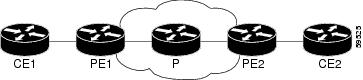
Figure 1 is a sample topology that helps illustrate how LMI works.
Figure 1 Sample Topology
In Figure 1, note the following:
•
•
•
•
How the LMI protocol behaves depends on whether you have DLCI-to-DLCI or port-to-port connections.
DLCI-to-DLCI Connections
If you have DLCI-to-DLCI connections, LMI runs locally on the Frame Relay ports between the PE and CE devices.
•
•
–
–
–
–
For DTE/DCE configurations, the following LMI behavior exists:
The Frame Relay device accessing the network (DTE) does the polling. The network device (DCE) responds to the LMI polls. Therefore, if a problem exists on the DTE side, the DCE is not aware of the problem, because it does not poll.
Port-to-Port Connections
If you have port-to-port connections, the PE routers do not participate in the LMI status-checking procedures. LMI operates between the customer edge (CE) routers only. The CE routers must be configured as DCE-DTE or NNI-NNI.
For More Information About LMI
For information about LMI, including configuration instructions, see the following document:
Configuring Frame Relay, Configuring the LMI
http://www.cisco.com/univercd/cc/td/doc/product/software/ios122/122cgcr/fwan_c/wcffrely.htm#xtocid8
How to Configure HDLC and PPP over MPLS
With HDLC over MPLS, the whole HDLC packet is transported. The ingress PE router removes only the HDLC flags and frame check sequence (FCS) bits. The contents of the packet are not used or changed.
With PPP over MPLS, the ingress PE router removes the flags, address, control field, and the FCS.
Configuring HDLC and PPP over MPLS
Perform this task to set up HDLC and PPP connections.
SUMMARY STEPS
1.
2.
3.
4.
5.
DETAILED STEPS
How to Configure Distributed CEF Mode
Supported Platforms:
•
•
Note
Distributed CEF mode is supported on the Cisco 7500 series routers for Frame Relay, HDLC, and PPP. In distributed CEF mode, the switching process occurs on the VIPs that support switching. When distributed CEF is enabled, VIP port adapaters maintain identical copies of the forwarding information base (FIB) and adjacency tables. The port adapters perform the express forwarding between port adapters, relieving the Route Switch Processor (RSP) from performing the switching. Distributed CEF uses an inter process communications (IPC) mechanism to ensure synchronization of FIBs and adjacency tables between the RSP and port adapters.
Enabling Distributed CEF
To enable distributed CEF on the Cisco 7500 series routers, issue the ip cef distributed command.
How to Configure MPLS Traffic Engineering Fast Reroute
Supported Platforms:
•
•
•
•
This feature allows AToM to use MPLS Traffic Engineering (TE) tunnels with Fast Reroute support. AToM VCs can be rerouted around a failed link or node at the same time as MPLS and IP prefixes.
Configuring MPLS TE Fast Reroute
Enabling Fast Reroute on AToM does not require any special commands; you can use standard fast reroute commands. At the ingress PE, an AToM tunnel is protected by Fast Reroute when it is routed to an FRR-protected TE tunnel. Both link and node protection are supported for AToM VCs at the ingress PE. For more information on configuring MPLS TE Fast Reroute, see the following:
MPLS Traffic Engineering (TE)—Link and Node Protection, with RSVP Hellos Support
http://www.cisco.com/univercd/cc/td/doc/product/software/ios120/120newft/120limit/120s/120s23/fs_frrnd.htm
Fast Reroute Configuration Example
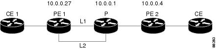
The following configuration example and Figure 2 show the configuration of Fast Reroute on AToM PE routers.
Routers PE1 and PE2 have the following characteristics:
•
•
•
Figure 2 Fast Reroute Configuration
PE1 (Java)mpls label protocol ldpmpls traffic-eng tunnelsmpls ldp router-id Loopback1 force!pseudowire-class T41encapsulation mplspreferred-path interface Tunnel41 disable-fallback!pseudowire-class IP1encapsulation mplspreferred-path peer 1.4.0.1 disable-fallback!interface Loopback1ip address 1.0.0.27 255.255.255.255!interface Tunnel1ip unnumbered Loopback1tunnel destination 1.0.0.1tunnel mode mpls traffic-engtunnel mpls traffic-eng priority 1 1tunnel mpls traffic-eng bandwidth 10000tunnel mpls traffic-eng path-option 1 explicit name FRR!interface Tunnel41ip unnumbered Loopback1tunnel destination 1.0.0.4tunnel mode mpls traffic-engtunnel mpls traffic-eng priority 1 1tunnel mpls traffic-eng bandwidth 1000tunnel mpls traffic-eng path-option 1 explicit name Chino_1tunnel mpls traffic-eng fast-reroute!interface POS0/0description Joe POS8/0/0ip address 1.1.0.2 255.255.255.252mpls traffic-eng tunnelsmpls traffic-eng backup-path Tunnel1crc 16clock source internalpos ais-shutpos report lrdiip rsvp bandwidth 155000 155000!interface POS0/3description Joe POS10/1/0ip address 1.1.0.14 255.255.255.252mpls traffic-eng tunnelscrc 16clock source internalip rsvp bandwidth 155000 155000!interface gigabitethernet3/0.1encapsulation dot1Q 203xconnect 1.0.0.4 2 pw-class IP1!interface gigabitethernet3/0.2encapsulation dot1Q 204xconnect 1.0.0.4 4 pw-class T41!router ospf 1network 1.0.0.0 0.255.255.255 area 0mpls traffic-eng router-id Loopback1mpls traffic-eng area 0!ip classlessip route 1.4.0.1 255.255.255.255 Tunnel41!ip explicit-path name Java_1 enablenext-address 1.4.1.2next-address 1.1.0.10P (Joe)
ip cefmpls traffic-eng tunnels!interface Loopback1ip address 1.0.0.1 255.255.255.255!interface FastEthernet1/0/0ip address 1.4.1.2 255.255.255.0mpls traffic-eng tunnelsip rsvp bandwidth 10000 10000!interface POS8/0/0description Java POS0/0ip address 1.1.0.1 255.255.255.252mpls traffic-eng tunnelspos ais-shutpos report lrdiip rsvp bandwidth 155000 155000!interface POS10/1/0description Java POS0/3ip address 1.1.0.13 255.255.255.252mpls traffic-eng tunnelsip rsvp bandwidth 155000 155000!router ospf 1network 1.0.0.0 0.255.255.255 area 0mpls traffic-eng router-id Loopback1mpls traffic-eng area 0PE2 (Chino)
ip cefmpls label protocol ldpmpls traffic-eng tunnelsmpls ldp router-id Loopback1 force!interface Loopback1ip address 1.0.0.4 255.255.255.255!interface loopback 2ip address 1.4.0.1 255.255.255.255!interface Tunnel27ip unnumbered Loopback1tunnel destination 1.0.0.27tunnel mode mpls traffic-engtunnel mpls traffic-eng autoroute announcetunnel mpls traffic-eng priority 1 1tunnel mpls traffic-eng bandwidth 1000tunnel mpls traffic-eng path-option 1 explicit name Java_1!interface FastEthernet0/0.2encapsulation dot1Q 203xconnect 1.0.0.27 2 encapsulation mpls!interface FastEthernet0/0.3encapsulation dot1Q 204xconnect 1.0.0.27 4 encapsulation mpls!interface FastEthernet1/1ip address 1.4.1.1 255.255.255.0mpls traffic-eng tunnelsip rsvp bandwidth 10000 10000!router ospf 1network 1.0.0.0 0.255.255.255 area 0mpls traffic-eng router-id Loopback1mpls traffic-eng area 0!ip explicit-path name Java_1 enablenext-address 1.4.1.2next-address 1.1.0.10Verifying Fast Reroute
Issue the show mpls traffic-eng tunnels command to display status information about the tunnels.
Java# show mpls traffic-eng tunnels tunnel 41Name: Java_t41 (Tunnel41) Destination: 1.0.0.4Status:Admin: up Oper: up Path: valid Signalling: connectedpath option 1, type explicit Chino_1 (Basis for Setup, path weight 2)Config Parameters:Bandwidth: 1000 kbps (Global) Priority: 1 1 Affinity: 0x0/0xFFFFMetric Type: TE (default)AutoRoute: disabled LockDown: disabled Loadshare: 1000 bw-basedauto-bw: disabledInLabel : -OutLabel : POS0/0, 35FRR OutLabel : Tunnel1, 35RSVP Signalling Info:Src 1.0.0.27, Dst 1.0.0.4, Tun_Id 41, Tun_Instance 48RSVP Path Info:My Address: 1.0.0.27Explicit Route: 1.1.0.1 1.4.1.2 1.4.1.1 1.0.0.4Record Route: NONETspec: ave rate=1000 kbits, burst=1000 bytes, peak rate=1000 kbitsRSVP Resv Info:Record Route: 1.4.1.2(35) 1.4.1.1(0)Fspec: ave rate=1000 kbits, burst=1000 bytes, peak rate=17179869 kbitsShortest Unconstrained Path Info:Path Weight: 2 (TE)Explicit Route: 1.1.0.1 1.4.1.2 1.4.1.1 1.0.0.4History:Tunnel:Time since created: 3 days, 7 hours, 49 minutesTime since path change: 3 days, 7 hours, 46 minutesCurrent LSP:Uptime: 3 days, 7 hours, 31 minutesSelection: reoptimationPrior LSP:ID: path option 1 [42]Removal Trigger: re-route path verification failedIssue the show mpls interfaces command to display information about the TE tunnel.
Java# show mpls interfaces tunnel 41 detailInterface Tunnel41:MPLS TE Tunnel HeadIP labeling not enabledLSP Tunnel labeling not enabledBGP labeling not enabledMPLS not operationalMTU = 4466Tun hd Untagged 0 Tu41 point2pointMAC/Encaps=4/8, MRU=4470, Tag Stack{28}, via PO0/00F008847 0001C000No output feature configuredFast Reroute Protection via {Tu1, outgoing label 28}Issue the show mpls traffic-eng fast-reroute database command to display information about the status of the tunnels.
Java# show mpls traffic-eng fast-reroute databaseTunnel head end item frr information:Protected tunnel In-label Out intf/label FRR intf/label StatusTunnel41 Tun hd PO0/0:Untagged Tu1:28 readyPrefix item frr information:Prefix Tunnel In-label Out intf/label FRR intf/label Status1.4.0.1/32 Tu41 12313 PO0/0:Untagged Tu1:28 readyTroubleshooting Tips
You can issue the debug mpls l2transport fast-reroute command to debug Fast Reroute.
Note
In the following example, the primary link is disabled, which causes the backup tunnel (Tunnel 1) to become the primary path.
Java# execute-on slot 3 debug mpls l2transport fast-reroute========= Line Card (Slot 3) =========AToM fast reroute debugging is onSLOT 3:Sep 16 17:58:56.346: AToM SMGR: Processing TFIB FRR event for 1.4.0.1SLOT 3:Sep 16 17:58:56.346: AToM SMGR: Finished processing TFIB FRR event for 1.4.0.1SLOT 3:Sep 16 17:58:56.346: AToM SMGR: Processing TFIB FRR event for Tunnel41SLOT 3:Sep 16 17:58:56.346: AToM SMGR: Finished processing TFIB FRR event for Tunnel41Sep 16 17:58:58.342: %LINK-3-UPDOWN: Interface POS0/0, changed state to downSep 16 17:58:58.342: %OSPF-5-ADJCHG: Process 1, Nbr 1.0.0.1 on POS0/0 from FULL to DOWN, Neighbor Down: Interface down or detachedSep 16 17:58:59.342: %LINEPROTO-5-UPDOWN: Line protocol on Interface POS0/0, changed state to downHow to Configure Tunnel Selection
Supported Platforms:
•
•
•
•
This feature allows you to specify the path that traffic uses. You can specify either an MPLS TE tunnel or destination IP address/DNS name.
You also have the option of specifying whether the VCs should use the default path (the path LDP used for signaling) if the preferred path is unreachable. This option is enabled by default; you must explicitly disable it.
Configuring Tunnel Selection
You configure tunnel selection when you set up the pseudowire class. You enable tunnel selection with the preferred-path command. Then, you apply the pseudowire class to an interface that has been configured to transport AToM packets.
SUMMARY STEPS
1.
2.
3.
4.
5.
6.
7.
8.
DETAILED STEPS
Tunnel Selection Configuration Guidelines
The following guidelines provide more information about configuring tunnel selection.
•
•
•
•
•
•
Tunnel Selection Configuration Example
The following example sets up two preferred paths for PE1. One preferred path specifies an MPLS traffic engineering tunnel. The other preferred path specifies an IP address of a loopback address on PE2. There is a static route configured on PE1 that uses a TE tunnel to reach the IP address on PE2.
PE1:
mpls label protocol ldpmpls traffic-eng tunnelstag-switching tdp router-id Loopback0pseudowire-class pw1encapsulation mplspreferred-path interface Tunnel1 disable-fallback!pseudowire-class pw2encapsulation mplspreferred-path peer 16.18.18.18!interface Loopback0ip address 75.2.2.2 255.255.255.255no ip directed-broadcastno ip mroute-cache!interface Tunnel1ip unnumbered Loopback0no ip directed-broadcasttunnel destination 16.16.16.16tunnel mode mpls traffic-engtunnel mpls traffic-eng priority 7 7tunnel mpls traffic-eng bandwidth 1500tunnel mpls traffic-eng path-option 1 explicit name path-tu1!interface Tunnel2ip unnumbered Loopback0no ip directed-broadcasttunnel destination 16.16.16.16tunnel mode mpls traffic-engtunnel mpls traffic-eng priority 7 7tunnel mpls traffic-eng bandwidth 1500tunnel mpls traffic-eng path-option 1 dynamic!interface gigabitethernet0/0/0no ip addressno ip directed-broadcastno negotiation auto!interface gigabitethernet0/0/0.1encapsulation dot1Q 222no ip directed-broadcastxconnect 16.16.16.16 101 pw-class pw1!interface ATM1/0/0no ip addressno ip directed-broadcastno atm enable-ilmi-trapno atm ilmi-keepalivepvc 0/50 l2transportencapsulation aal5xconnect 16.16.16.16 150 pw-class pw2!interface Ethernet2/0/1ip address 9.0.0.1 255.255.255.0no ip directed-broadcasttag-switching ipmpls traffic-eng tunnelsip rsvp bandwidth 15000 15000!router ospf 1log-adjacency-changesnetwork 9.0.0.0 0.0.0.255 area 0network 75.2.2.2 0.0.0.0 area 0mpls traffic-eng router-id Loopback0mpls traffic-eng area 0!ip route 16.18.18.18 255.255.255.255 Tunnel2!ip explicit-path name path-tu1 enablenext-address 9.0.0.1index 3 next-address 11.0.0.1PE2:
mpls label protocol ldpmpls traffic-eng tunnelsmpls ldp router-id Loopback0interface Loopback0ip address 16.16.16.16 255.255.255.255no ip directed-broadcastno ip mroute-cache!interface Loopback2ip address 16.18.18.18 255.255.255.255no ip directed-broadcast!interface Ethernet3/1ip address 11.0.0.2 255.255.255.0no ip directed-broadcastmpls traffic-eng tunnelsmpls ipno cdp enableip rsvp bandwidth 15000 15000!interface Ethernet3/3no ip addressno ip directed-broadcastno cdp enable!interface Ethernet3/3.1encapsulation dot1Q 222no ip directed-broadcastno cdp enablempls l2transport route 75.2.2.2 101!interface ATM5/0no ip addressno ip directed-broadcastno atm enable-ilmi-trapno atm ilmi-keepalivepvc 0/50 l2transportencapsulation aal5xconnect 75.2.2.2 150 encapsulation mpls!router ospf 1log-adjacency-changesnetwork 11.0.0.0 0.0.0.255 area 0network 16.16.16.16 0.0.0.0 area 0mpls traffic-eng router-id Loopback0mpls traffic-eng area 0Verifying Tunnel Selection
The show mpls l2transport vc command shows the following information about the VCs:
•
•
Router# show mpls l2transport vc detailLocal interface: Gi0/0/0.1 up, line protocol up, Eth VLAN 222 upDestination address: 16.16.16.16, VC ID: 101, VC status: upPreferred path: Tunnel1, activeDefault path: disabledTunnel label: 3, next hop point2pointOutput interface: Tu1, imposed label stack {17 16}Create time: 00:27:31, last status change time: 00:27:31Signaling protocol: LDP, peer 16.16.16.16:0 upMPLS VC labels: local 25, remote 16Group ID: local 0, remote 6MTU: local 1500, remote 1500Remote interface description:Sequencing: receive disabled, send disabledVC statistics:packet totals: receive 10, send 10byte totals: receive 1260, send 1300packet drops: receive 0, send 0Local interface: AT1/0/0 up, line protocol up, ATM AAL5 0/50 upDestination address: 16.16.16.16, VC ID: 150, VC status: upPreferred path: 16.18.18.18, activeDefault path: readyTunnel label: 3, next hop point2pointOutput interface: Tu2, imposed label stack {18 24}Create time: 00:15:08, last status change time: 00:07:37Signaling protocol: LDP, peer 16.16.16.16:0 upMPLS VC labels: local 26, remote 24Group ID: local 2, remote 0MTU: local 4470, remote 4470Remote interface description:Sequencing: receive disabled, send disabledVC statistics:packet totals: receive 0, send 0byte totals: receive 0, send 0packet drops: receive 0, send 0Troubleshooting Tunnel Selection
You can use the debug mpls l2transport vc event command to troubleshoot tunnel selection. For example, if the tunnel interface that is used for the preferred path is shut down, the default path is enabled. The debug mpls l2transport vc event command provides the following output:
AToM SMGR [75.2.2.2, 101]: Processing imposition update, vc_handle 62091860, update_action
3, remote_vc_label 16
AToM SMGR [75.2.2.2, 101]: selected route no parent rewrite: tunnel not upAToM SMGR [75.2.2.2, 101]: Imposition Programmed, Output Interface: Et3/2How to Estimate the Size of Packets Traveling Through the Core Network
The following calculation helps you determine the size of the packets traveling through the core network. You set the MTU on the core-facing interfaces of the P and PE routers to accommodate packets of this size. The MTU should be greater than or equal to the total bytes of the items in the following equation:
Core MTU >= (Edge MTU + Transport header + AToM header + (MPLS label stack * MPLS label
size))
The following sections describe the variables used in the equation.
Edge MTU
The edge MTU is the MTU for the customer-facing interfaces.
Transport header
The Transport header depends on the transport type. Table 2 lists the specific sizes of the headers.
AToM Header
The AToM header is 4 bytes (control word). The control word is optional for Ethernet, PPP, HDLC, and cell relay transport types. However, the control word is required for Frame Relay, and ATM AAL5 transport types.
MPLS Label Stack
The MPLS label stack size depends on the configuration of the core MPLS network.
•
•
•
•
•
•
•
Other circumstances can increase the MPLS label stack size. Therefore, analyze the complete data path between the AToM tunnel endpoints and determine the maximum MPLS label stack size for your network. Then multiply the label stack size by the size of the MPLS label.
Example of Estimating Packet Size
Example 2 estimates the size of packets. The example uses the following assumptions:
•
•
•
•
Example 2 Estimating the MTU for Packets
Edge MTU + Transport header + AToM header + (MPLS label stack * MPLS Label) = Core MTU1500 + 18 + 0 + (2 * 4 ) = 1526You must configure the P and PE routers in the core to accept packets of 1526 bytes. See the following section for setting the MTU size on the P and PE routers.
Changing the MTU Size on the P and PE Routers
Once you determine the MTU size to set on your P and PE routers, you can issue the mtu command on the routers to set the MTU size. The following example specifies an MTU of 1526 bytes.
Router(config-if)# mtu 1526
Note
How To Configure QOS with AToM
This section explains how to configure QOS with AToM and includes the following procedures:
•
•
•
How to Set Experimental Bits with AToM
Supported Platforms:
•
•
•
•
For configuration steps and examples, see the "Setting the EXP Bits" section.
MPLS AToM uses the three experimental bits in a label to determine the queue of packets. You statically set the experimental bits in both the VC label and the LSP tunnel label, because the LSP tunnel label might be removed at the penultimate router. The following sections explain the transport-specific implementations of the EXP bits.
ATM AAL5 over MPLS and EXP Bits
•
•
•
ATM Cell Relay over MPLS and EXP Bits
•
•
•
Ethernet over MPLS and EXP Bits
On the Cisco 12000 Series Routers
•
•
•
On the Cisco 7200 and 7500 Series Routers
•
–
–
•
•
On the Cisco 10720 Router
Table 3 lists the commands that are supported on the Cisco 10720 router for Ethernet over MPLS. The letter Y means that the command is supported on that interface. A dash (—) means that command is not supported on that interface.
Note
Frame Relay over MPLS and EXP Bits
If you do not assign values to the experimental bits, the priority bits in the header's "tag control information" field are set to zero.
On the Cisco 7500 series routers, dCEF must be enabled before you set the experimental bits.
HDLC over MPLS and PPP over MPLS and EXP Bits
If you do not assign values to the experimental bits, zeros are written into the experimental bit fields.
On the Cisco 7500 series routers, enable dCEF before setting the experimental bits.
Setting the EXP Bits
Set the experimental bits in both the VC label and the LSP tunnel label. You set the experimental bits in the VC label, because the LSP tunnel label might be removed at the penultimate router.
Perform this task to set the experimental bits.
Note
SUMMARY STEPS
1.
2.
3.
4.
5.
6.
7.
8.
9.
DETAILED STEPS
Displaying the Traffic Policy Assigned to an Interface
To display the traffic policy attached to an interface, use the show policy-map interface command.
Examples of Setting the EXP Bits on the Cisco 12000 Series Routers
The following examples set the EXP bits on the different transport types for the Cisco 12000 series routers.
Example 3 Setting the EXP Bits for ATM Single Cell Relay over MPLS
Class Map match-any atm-class!Policy Map exp7Class atm-classset mpls experimental 7!interface ATM4/0no ip addressno ip directed-broadcastatm clock INTERNALno atm enable-ilmi-trapno atm ilmi-keepalivepvc 0/110 l2transportxconnect 5.5.5.5 1145 encapsulation mplsservice-policy input exp7Example 4 Setting the EXP Bits for Frame Relay over MPLS
Class Map match-any fr-class!Policy Map exp7Class fr-classset mpls experimental 7!interface POS4/0.1 point-to-pointno ip directed-broadcastswitched-dlci 106service-policy input exp7!connect frompls101 POS4/0 106 l2transportxconnect 3.3.3.3 2034 encapsulation mplspvc 0/120 l2transportencapsulation aal0xconnect 5.5.5.5 1045 encapsulation mplsservice-policy input exp7Example 5 Setting the EXP Bits for Ethernet Port Mode over MPLS
Class Map match-any eport-class!Policy Map exp7Class eport-classset mpls experimental 7!int Gigaethernet4/0xconnect 5.5.5.5 1045 encapsulation mplsservice-policy input exp7Example 6 Setting the EXP Bits for HDLC over MPLS
Class Map match-any hdlc-class!Policy Map exp7Class hdlc-classset mpls experimental 7!interface POS4/0xconnect 5.5.5.5 1045 encapsulation mplsservice-policy input exp7Example 7 Setting the EXP Bits for Ethernet VLAN over MPLS
Class Map match-any evlan-class!Policy Map exp7Class evlan-classset mpls experimental 7!int Gigaethernet4/0.1encapsulation dot1Q 200xconnect 5.5.5.5 1045 encapsulation mplsservice-policy input exp7Example 8 Setting the EXP Bits for PPP over MPLS
Class Map match-any ppp-class!Policy Map exp7Class ppp-classset mpls experimental 7!interface POS4/0encapsulation pppxconnect 5.5.5.5 1045 encapsulation mplsservice-policy input exp7Using 802.1Q P Bits to Determine the Experimental Bit Settings
The following configuration steps let you configure class maps and policy maps to control the setting of the EXP bit based on the 802.1Q P bit setting. This procedure applies only to Ethernet over MPLS in VLAN mode for the Cisco 12000 series routers.
SUMMARY STEPS
1.
2.
3.
4.
5.
6.
7.
8.
9.
DETAILED STEPS
Example:
class-map match-any barneymatch cos 2!policy-map eompls1class barneyset mpls experimental 1!int gig 0/0.1service-policy input eompls1How to Configure QOS Features with the Cisco 12000 Series Routers
The following QoS features are supported by AToM in 12.0(25)S on the Cisco 12000 series routers.
Traffic Policing
Supported on ATM AAL5, ATM Cell Relay (VC and VP modes), and Frame Relay over MPLS. See Configuring Traffic Policing with the Cisco 12000 Series Routers for more information.
Traffic Shaping
Supported on ATM AAL5 and ATM Cell Relay (VC and VP modes) For information about configuring and using Traffic Shaping on ATM interfaces on the Cisco 12000 series router, see the following information:
•
http://www.cisco.com/univercd/cc/td/doc/product/software/ios120/120newft/120limit/120s/120s22/8_oc3_lc.htm
•
http://www.cisco.com/warp/public/121/atmlcshaping_12141.html
Configuring Traffic Policing with the Cisco 12000 Series Routers
Supported Platforms:
•
Traffic policing operates on incoming traffic. When enabled, policing prevents traffic congestion by treating traffic as either committed or excess. You specify the parameters for committed and excess traffic. Traffic that falls within the committed rate parameters is transmitted, whereas traffic that exceeds the parameters is dropped or transmitted with a different priority.
How traffic policing handles packets depends on the configuration of the committed information rate (CIR), peak information rate (PIR), burst committed (BC), and peak burst (BE) parameters and the conform, exceed, and violate actions.
Note
How Traffic Policing Treats ATM Packets
Table 4 shows how ATM packets are handled on the Cisco 12000 series routers with traffic policing.
Traffic Policing on ATM AAL5 over MPLS with the Cisco 12000 Series Router Line Cards
On Cisco 12000 series routers, the policing function measures traffic in different ways for E2 and E0 ATM line cards. Therefore, when you display policing statistics, the results will be different for different line cards.
•
–
–
–
•
Further, arithmetic round-off errors can allow higher bursts of committed and excess traffic than you specified. To keep the burst traffic within the specified limits, specify a minimum excess burst.
How Traffic Policing Treats Frame Relay Packets
Table 5 shows how Frame Relay packets are handled on the Cisco 12000 series routers with traffic policing.
Configuration Guidelines
To configure traffic policing, you create a traffic class and a traffic policy and attach the traffic policy to a specified VC or subinterface. You perform these tasks using the Modular QoS command-line interface (CLI). For information on the Modular QoS CLI, see "Configuring the Modular Quality of Service Command-Line Interface" at the following URL:
http://www.cisco.com/univercd/cc/td/doc/product/software/ios122/122cgcr/fqos_c/fqcprt8/qcfmcli2.htm#89799
The following list outlines guidelines specific to the Cisco 12000 series router and traffic policing:
•
http://www.cisco.com/univercd/cc/td/doc/product/software/ios122/122newft/122t/122t4/ft2rtplc.htm
•
•
•
•
•
Configuring Traffic Policing for ATM AAL5 and ATM Cell Relay on the Cisco 12000 Series Routers
Perform this task to enable traffic policing for ATM cell relay and ATM AAL5.
SUMMARY STEPS
1.
2.
3.
4.
5.
6.
7.
8.
9.
or
encapsulation aal0
10.
11.
DETAILED STEPS
Traffic Policing for ATM Cell Relay over MPLS Configuration Example
Example 9 shows an example of configuring traffic policing with ATM Cell Relay over MPLS.
Example 9 Traffic Policing for ATM Cell Relay over MPLS with the Cisco 12000 Series Routers
class map match-any atm-class!policy map atm-policyclass atm-classpolice cir 64000 bc 1000 pir 128000 be 2000conform-action transmit exceed-action set-clp-transmit violate-action drop!interface ATM4/0no ip addressno ip directed-broadcastatm clock INTERNALno atm enable-ilmi-trapno atm ilmi-keepalivepvc 0/110 l2transportxconnect 5.5.5.5 1145 encapsulation mplsservice-policy input atm-policy!pvc 0/120 l2transportencapsulation aal0xconnect 5.5.5.5 1045 encapsulation mplsservice-policy input atm-policyConfiguring Traffic Policing for Frame Relay on the Cisco 12000 Series Routers
Perform this task to enable traffic policing for Frame Relay.
SUMMARY STEPS
1.
2.
3.
4.
5.
6.
7.
8.
9.
10.
11.
12.
13.
DETAILED STEPS
Traffic Policing for Frame Relay over MPLS Configuration Example
Example 10 configures traffic policing for Frame Relay over MPLS on the Cisco 12000 series routers.
Example 10 Traffic Policing for Frame Relay over MPLS with the Cisco 12000 Series Routers
class map match-any fr-class!policy map frtp-policyclass fr-classpolice cir 64000 bc 1000 pir 128000 be 2000conform-action transmit exceed-action set-frde-transmit violate-action drop!interface POS4/0encapsulation frame-relay cisco!interface POS4/0.1 point-to-pointno ip directed-broadcastswitched-dlci 106service-policy input frtp-policyconnect frompls101 POS4/0 106 l2transportxconnect 3.3.3.3 2034 encapsulation mplsHow to Configure QoS Features with the Cisco 7500 Series Routers
The following QoS features are supported by AToM in 12.0(25)S on the Cisco 7500 series routers.
Service Policy
Can be applied to:
•
•
Can be applied to:
•
•
•
Classification
Supports the following commands:
•
•
•
Supports the following commands:
•
Marking
Supports the following commands:
•
•
•
Supports the following commands:
•
Policing
Supports the following:
•
Supports the following:
•
Queueing and Shaping
Supports the following:
•
•
•
•
Supports the following:
•
•
•
Refer to the following documentation for information about these features:
•
http://www.cisco.com/univercd/cc/td/doc/product/software/ios121/121newft/121t/121t5/dtllqvip.htm
•
http://www.cisco.com/univercd/cc/td/doc/product/software/ios122/122newft/122t/122t2/ftpoli.htm
•
http://www.cisco.com/univercd/cc/td/doc/product/software/ios121/121newft/121t/121t5/cbpmark2.htm
•
http://www.cisco.com/univercd/cc/td/doc/product/software/ios121/121newft/121t/121t5/dtcbwred.htm
•
http://www.cisco.com/univercd/cc/td/doc/product/software/ios122/122newft/122t/122t13/ftpcdlci.htm
Setting the Frame Relay Discard Eligibility Bit on the Cisco 7500 Series Routers
You can use the discard eligibility (DE) bit in the address field of a frame relay frame to prioritize frames in congested frame relay networks. The frame relay DE bit has only one bit and can therefore only have two settings, 0 or 1. If congestion occurs in a frame relay network, frames with the DE bit set to 1 are discarded before frames with the DE bit set to 0. Therefore, important traffic should have the DE bit set to 0, while less important traffic should be forwarded with the DE bit set at 1. The default DE bit setting is 0. You can change the DE bit setting to 1 with the set fr-de command.
Note
Setting the Frame Relay DE Bit on the Cisco 7500 Series Routers
Perform this task to set the Frame Relay DE bit to 1 on the Cisco 7500 series routers.
SUMMARY STEPS
1.
2.
3.
4.
5.
DETAILED STEPS
Setting the Frame Relay DE Bit Configuration Example
The following example shows how to configure the service policy called set-de and attach it to an interface. In this example, the class map called data evaluates all packets exiting the interface for an IP precedence value of 1. If the exiting packet has been marked with the IP precedence value of 1, the packet's DE bit is set to 1.
class-map datamatch ip precedence 1policy-map SET-DEclass dataset fr-deinterface Serial0/0/0encapsulation frame-relayinterface Serial0/0/0.1 point-to-pointip address 161.222.249.194 255.255.255.252frame-relay interface-dlci 100service output SET-DEMatching the Frame Relay Discard Eligibility Bit on the Cisco 7500 Series Routers
You can use the match fr-de command to enable frames with a DE bit setting of 1 to be considered a member of a defined class and forwarded according to the specifications set in the service policy.
Matching the Frame Relay DE Bit on the Cisco 7500 Series Routers
Perform this task to classify frames with the FR DE bit set to 1.
SUMMARY STEPS
1.
2.
3.
4.
DETAILED STEPS
Matching the Frame Relay DE Bit Configuration Example
The following example shows how to configure the service policy called match-de and attach it to an interface. In this example, the class map called data evaluates all packets entering the interface for a DE bit setting of 1. If the entering packet has been a DE bit value of 1, the packet's EXP bit setting is set to 3.
class-map datamatch fr-depolicy-map MATCH-DEclass dataset mpls exp 3ip routingip cef distributedmpls label protocol ldpinterface Loopback0ip address 20.20.20.20 255.255.255.255interface Ethernet1/0/0ip address 91.0.0.2 255.255.255.0tag-switching ipinterface Serial4/0/0encapsulation frame-relayservice input MATCH-DEconnect 100 Serial4/0/0 100 l2transportxconnect 10.10.10.10 100 encapsulation mplsAdditional References
For additional information related to Any Transport over MPLS, refer to the following references:
•
•
Related Documents
Any Transport over MPLS
Data Sheet: Any Transport over MPLS
White Paper: Cisco Any Transport over MPLS
Layer 2 Tunnel Protocol Version 3 (L2TPv3) provides the ability to tunnel any Layer 2 payload over an IP core network using Layer 2 virtual private networks (L2VPNs).
Layer 2 Tunnel Protocol Feature Summary
Layer 2 Tunneling Protocol: A Feature in Cisco IOS Software
Layer 2 Tunnel Protocol Version 3 (L2TPv3) Feature Module
Standards
draft-martini-l2circuit-trans-mpls-08.txt
Transport of Layer 2 Frames Over MPLS
draft-martini-l2circuit-encap-mpls-04.txt
Encapsulation Methods for Transport of Layer 2 Frames Over MPLS
1 Not all supported standards are listed.
ATM AAL5 over MPLS and ATM Cell Relay over MPLS:
MPLS LDP MIB (MPLS-LDP-MIB.my)
ATM MIB (ATM-MIB.my)
CISCO AAL5 MIB (CISCO-AAL5-MIB.my)
Cisco Enterprise ATM Extension MIB (CISCO-ATM-EXT-MIB.my)
Supplemental ATM Management Objects (CISCO-IETF-ATM2-PVCTRAP-MIB.my)
Interfaces MIB (IF-MIB.my)
Ethernet over MPLS
CISCO-ETHERLIKE-CAPABILITIES.my
Ethernet MIB (ETHERLIKE-MIB.my)
Interfaces MIB (IF-MIB.my)
MPLS LDP MIB (MPLS-LDP-MIB.my)
Frame Relay over MPLS
Cisco Frame Relay MIB (CISCO-FRAME-RELAY-MIB.my)
Interfaces MIB (IF-MIB.my)
MPLS LDP MIB (MPLS-LDP-MIB.my)
HDLC and PPP over MPLS
MPLS LDP MIB (MPLS-LDP-MIB.my)
Interface MIB (IF-MIB.my)
To obtain lists of supported MIBs by platform and Cisco IOS release, and to download MIB modules, go to the Cisco MIB website on Cisco.com at the following URL:
http://www.cisco.com/public/sw-center/netmgmt/cmtk/mibs.shtml
1 Not all supported MIBs are listed.
MIBs
To locate and download MIBs for selected platforms, Cisco IOS releases, and feature sets, use Cisco MIB Locator found at the following URL:
http://tools.cisco.com/ITDIT/MIBS/servlet/index
If Cisco MIB Locator does not support the MIB information that you need, you can also obtain a list of supported MIBs and download MIBs from the Cisco MIBs page at the following URL:
http://www.cisco.com/public/sw-center/netmgmt/cmtk/mibs.shtml
To access Cisco MIB Locator, you must have an account on Cisco.com. If you have forgotten or lost your account information, send a blank e-mail to cco-locksmith@cisco.com. An automatic check will verify that your e-mail address is registered with Cisco.com. If the check is successful, account details with a new random password will be e-mailed to you. Qualified users can establish an account on Cisco.com by following the directions found at this URL:
RFCs
RFC 3032
MPLS Label Stack Encoding
RFC 3036
LDP Specification
1 Not all supported RFC are listed.
Technical Assistance
Command Reference
This section documents new and modified commands. All other commands used with this feature are documented in the Cisco IOS Release 12.0 command reference publications.
New Commands
•
Modified Commands
atm mcpt-timers
To set up the cell-packing timers, which specify how long the provider edge (PE) router can wait for cells to be packed into a Multiprotocol Label Switching (MPLS) or Layer 2 Tunneling Protocol version 3 (L2TPv3) packet, use the atm mcpt-timers command in interface configuration mode. To disable the cell-packing timers, use the no form of this command.
atm mcpt-timers [timeout-1 timeout-2 timeout-3]
no atm mcpt-timers
Syntax Description
Defaults
By default, the timers are not set. If you enable the cell-packing timers, the default values for the PA-A3 port adapters are:
•
•
•
Command Modes
Interface configuration
Command History
12.0(25)S
This command was introduced.
12.0(29)S
Support for L2TPv3 sessions was added in Cisco IOS Release 12.0(29)S.
Usage Guidelines
For each timer, you specify the maximum cell packing timeout (MCPT). This value gives the cell-packing function a limited amount of time to complete. If the timer expires before the maximum number of cells are packed into an Any Transport over MPLS (AToM) or L2TPv3 packet, the packet is sent anyway.
The timeout's range of acceptable values depends on the ATM link speed. For the PA-A3 port adapter, the range of values is:
•
•
•
Examples
The following example sets the MCPT timers to 10, 60, and 90 microseconds, respectively.
Router# interface atm 1/0Router(config-if)# atm mcpt-timers 10 60 90Related Commands
atm mode cell-relay
To enable the Cisco 12000 series router engine 2 8-port OC-3 STM-1 ATM line card to send and receive ATM packets as part of the ATM single cell relay over MPLS feature, use the atm mode cell-relay command in interface configuration mode. To disable the line card from having the ability to send and receive ATM packets, use the no form of the command.
atm mode cell-relay
no atm mode cell-relay
Syntax Description
This command has no arguments or keywords.
Defaults
By default, the line card does not have the ability to send and receive ATM packets as part of the ATM single cell relay over MPLS feature.
Command Modes
Interface configuration
Command History
Usage Guidelines
•
–
–
–
–
•
Examples
The following example shows how Cisco 12000 series router engine 2 8-port OC-3 STM-1 ATM line card is configured for ATM Single Cell Relay over MPLS.
Router(config)# interface atm1/0Router(config-if)# atm mode cell-relayRouter(config-atm-vc)# pvc 1/100 l2transportRouter(config-atm-vc)# encapsulation aal0Router(config-atm-vc)# xconnect 10.0.0.1 123 encapsulation mplsRelated Commands
atm pvp
To create a permanent virtual path (PVP) used to multiplex (or bundle) one or more virtual circuits (VCs), use the atm pvp command in interface configuration mode. To remove a PVP, use the no form of this command.
atm pvp vpi [peak-rate] [l2transport]
no atm pvp vpi
Syntax Description
Defaults
PVP is not configured.
The default peak rate is the line rate.
Command Modes
Interface configuration
Command History
11.1
This command was introduced.
12.0(25)S
This command was updated to include the l2transport keyword.
Usage Guidelines
This command is commonly used to create a PVP that is used in multiplex circuit emulation service (CES) and data VCs.
The ATM-CES port adapter supports multiplexing of one or more VCs over a virtual path that is shaped at a constant bandwidth. For example, you can buy a virtual path service from an ATM service provider and multiplex both the CES and data traffic over the virtual path.
All subsequently created VCs with a vpi argument matching the vpi value specified with the atm pvp command are multiplexed onto this PVP. This PVP connection is an ATM connection where switching is performed on the VPI field of the cell only. A PVP is created and left up indefinitely. All VCs that are multiplexed over a PVP share and are controlled by the traffic parameters associated with the PVP.
Changing the peak-rate argument causes the ATM-CES port adapter to go down and then back up.
When you create a PVP, two VCs are created (VCI 3 and 4) by default. These VCs are created for VP end-to-end loopback and segment loopback operation, administration, and maintenance (OAM) support.
When you use the l2transport keyword with the atm pvp command, the command mode becomes the l2transport PVP submode. You must issue the l2transport keyword to configure the ATM cell relay over MPLS feature in port mode or to configure the ATM cell relay over L2TPv3 feature.
To verify the configuration of a PVP, use the show atm vp command in EXEC mode.
Examples
The following example creates a permanent virtual path with a peak rate of 2000 kbps. The subsequent VCs created are multiplexed onto this virtual path.
interface atm 6/0atm pvp 1 2000atm pvc 13 1 13 aal5snapexitinterface cbr 6/1ces circuit 0ces pvc 9 interface atm6/0 vpi 1 vci 100exitThe following example configures ATM Cell Relay over MPLS in port mode:
interface atm5/0atm pvp 1 l2transportxconnect 10.0.0.1 123 encapsulation mplsThe following example configures ATM Cell Relay over L2TPv3:
pw-class atm-xconnectencapsulation l2tpv3interface atm 4/1/0atm pvp 5 l2transportxconnect 10.0.3.201 888 pw-class atm-xconnectRelated Commands
show atm vp
Displays the statistics for all VPs on an interface or for a specific VP.
cell-packing
To enable ATM over MPLS to pack multiple ATM cells into each MPLS packet, use the cell-packing command in ATM VC or VP configuration mode. To disable cell-packing, use the no form of this command.
cell-packing [cells] [mcpt-timer timer]
no cell-packing
Syntax Description
Defaults
Cell packing is disabled.
Command Modes
ATM VC or VP configuration
Command History
Usage Guidelines
•
•
•
•
•
•
•
Please set mcpt values firstExamples
The following example shows cell packing enabled on an interface set up for VP mode. The cell-packing command specifies that 10 ATM cells be packed into each MPLS packet. The command also specifies that the second mcpt timer be used.
int atm 1/0atm mcpt-timer 1000 800 500atm pvp 100 l2transportxconnect 10.0.0.1 234 encapsulation mplscell-packing 10 mcpt-timer 2Related Commands
debug atm cell-packing
To enable the display of ATM cell relay cell packing debugging information, use the debug atm cell-packing command in privileged EXEC mode. To disable the display of debugging information, use the no form of this command.
debug atm cell-packing
no debug atm cell-packing
Syntax Description
This command has no arguments or keywords.
Defaults
Debugging of the cell-packing feature is not enabled.
Command Modes
Privileged EXEC
Command History
Examples
The following example enables debugging for ATM VCs that have been configured with cell packing.
Router# debug atm cell-packingATM Cell Packing debugging is on00:09:04: ATM Cell Packing: vc 1/100 remote mncp 22 validatedThe following example enables debugging for PVPs that have been configured with cell packing.
Router# debug atm cell-packingATM Cell Packing debugging is on00:12:33: ATM Cell Packing: vp 1 remote mncp 22 validatedThe output indicates that the router received the MNCP information from the remote PE router.
Related Commands
debug atm l2transport
To enable the display of debugging information related to ATM over MPLS, use the debug atm l2transport command in privileged EXEC mode. To disable the display of debugging information, use the no form of this command.
debug atm l2transport
no debug atm l2transport
Syntax Description
This command has no arguments or keywords.
Defaults
Debugging of ATM over MPLS is not enabled.
Command Modes
Privileged EXEC
Command History
Examples
The following example shows the events and messages when configuring ATM Cell Relay over MPLS in VP mode.
Router# debug atm l2transportATM L2transport Events and Errors debugging is onRouter# show debugATM L2transport:ATM L2transport Events and Errors debugging is onRouter(config-if)# atm pvp 24 l2transportRouter(cfg-if-atm-l2trans-pvp)# xconnect 11.11.11.11 700 pw-class vpRouter(cfg-if-atm-l2trans-pvp)# end00:14:51: ATM L2trans(ATM1/0): VP 24 is created00:14:51: ATM L2trans(ATM1/0): ckt_type 10, ckt_id 1000024 UP00:14:51: ATM L2trans(ATM1/0): VP 24, response is connect forwardedThe following example shows the events and messages when deleting a PVP.
Router(config-if)# no atm pvp 24 l2transport00:14:37: ATM L2trans(ATM1/0): ckt_type 10, ckt_id 1000024 DOWN00:14:37: ATM L2trans(ATM1/0): ckt_type 10, ckt_id 1000024 DOWN00:14:37: ATM L2trans(ATM1/0): remove xconnect circuit_type=10,circuit_id=100002400:14:37: ATM L2trans(ATM1/0): ckt_type 10, ckt_id 1000024 DOWNRelated Commands
Displays information about AToM circuits that have been enabled to route Layer 2 packets on a router.
debug mpls l2transport fast-reroute
To enable the display of Fast Reroute debugging information, use the debug mpls l2transport fast-reroute command in privileged EXEC mode. To stop the display of these messages, use the no form of this command.
debug mpls l2transport fast-reroute
no debug mpls l2transport fast-reroute
Syntax Description
This command has no arguments or keywords.
Defaults
Debugging of the fast reroute feature is not enabled.
Command Modes
Privileged EXEC
Command History
Usage Guidelines
This command does not display output on platforms where AToM Fast Reroute is implemented in the forwarding code. This command does not display output for the Cisco 7500 (both RP and VIP) series routers, 7200 series routers, and Cisco 12000 series route processor. The command does display output on Cisco 10720 Internet router line cards and Cisco 12000 series line cards.
Examples
In the following example, the primary link is disabled, which causes the backup tunnel (Tu1) to become the primary path.
Router# execute-on slot 3 debug mpls l2transport fast-reroute========= Line Card (Slot 3) =========AToM fast reroute debugging is onSLOT 3:Sep 16 17:58:56.346: AToM SMGR: Processing TFIB FRR event for 1.4.0.1SLOT 3:Sep 16 17:58:56.346: AToM SMGR: Finished processing TFIB FRR event for 1.4.0.1SLOT 3:Sep 16 17:58:56.346: AToM SMGR: Processing TFIB FRR event for Tunnel41SLOT 3:Sep 16 17:58:56.346: AToM SMGR: Finished processing TFIB FRR event for Tunnel41Sep 16 17:58:58.342: %LINK-3-UPDOWN: Interface POS0/0, changed state to downSep 16 17:58:58.342: %OSPF-5-ADJCHG: Process 1, Nbr 1.0.0.1 on POS0/0 from FULL to DOWN, Neighbor Down: Interface down or detachedSep 16 17:58:59.342: %LINEPROTO-5-UPDOWN: Line protocol on Interface POS0/0, changed state to downRelated Commands
show mpls traffic-eng fast-reroute database
Displays the contents of the Fast Reroute database.
encapsulation mpls
To specify that Multiprotocol Label Switching (MPLS) is used as the data encapsulation method for tunneling Layer 2 traffic over the pseudowire, use the encapsulation mpls command in pseudowire class configuration mode. To remove MPLS as the encapsulation method, use the no pseudowire-class command (see the Usage Guidelines for more information).
encapsulation mpls
no pseudowire-class
Syntax Description
This command has no arguments or keywords.
Defaults
No default behavior or values.
Command Modes
Pseudowire class configuration
Command History
Usage Guidelines
You must specify encapsulation mpls as part of the xconnect command or as part of a pseudowire class for the AToM VCs to work properly.
Once you specify the encapsulation mpls command, you cannot remove it using the no encapsulation mpls command. Nor can you change the command's setting using the encapsulation l2tpv3 command. Those methods result in the following error message:
Encapsulation changes are not allowed on an existing pw-class.To remove the command, you must delete the pseudowire with the no pseudowire-class command. To change the type of encapsulation, remove the pseudowire with the no pseudowire-class command and re-establish the pseudowire and specify the new encapsulation type.
Examples
The following example shows how to configure MPLS as the data encapsulation method for the pseudowire class ether-pw:
Router(config)# pseudowire-class ether-pwRouter(config-pw)# encapsulation mplsRelated Commands
Configures L2TPv3 as the data encapsulation method over IP networks.
Specifies the name of a pseudowire class and enters pseudowire class configuration mode.
match fr-de
To match packets with the Frame Relay discard eligibility bit set, use the match fr-de command in class-map configuration mode. To remove the match criteria, use the no form of this command.
match fr-de
no match fr-de
Syntax Description
This command has no keywords or arguments.
Defaults
This command has no default behavior or values.
Command Modes
Class-map configuration
Command History
Usage Guidelines
For Cisco IOS Release 12.0(25)S, this command is supported on the Cisco 7500 series router only.
Examples
The following example creates a class called match-fr-de and matches packets with the FR DE bit set.
Router(config)# class-map match-fr-deRouter(config-cmap)# match fr-deRouter(config)# exitRelated Commands
Changes the DE bit setting in the address field of a Frame Relay frame to 1 for all traffic leaving an interface.
preferred-path
To specify the path that traffic uses (an MPLS TE tunnel or destination IP address/DNS name), use the preferred-path command in pseudowire submode configuration mode. To disable tunnel selection, use the no form of this command.
preferred-path [interface tunnel tunnel-number | peer ip-address | host-name] [disable-fallback]
no preferred-path [interface tunnel tunnel-number | peer ip-address | host-name] [disable-fallback]
Syntax Description
Defaults
Tunnel selection is not enabled.
Command Modes
Pseudowire submode configuration
Command History
Usage Guidelines
The following guidelines provide more information about using this command:
•
•
•
•
•
•
•
Examples
The following example creates a pseudowire class and specifies Tunnel1 as the preferred path:
Router(config)# pseudowire-class pw1Router(config-pw)# encapsulation mplsRouter(config-pw)# preferred-path interface Tunnel1 disable-fallbackRelated Commands
Displays information about AToM VCs that have been enabled to route Layer 2 packets on a router.
remote circuit id
To use different VLAN IDs on each end of the MPLS tunnel for Ethernet over MPLS, use the remote circuit id command in xconnect configuration mode. To disable the VLAN ID rewrite functionality, use the no form of this command.
remote circuit id [remote-vlan-id]
no remote circuit id [remote-vlan-id]
Syntax Description
Defaults
VLAN ID rewrite is not enabled.
Command Modes
xconnect configuration mode
Command History
Usage Guidelines
The following guidelines provide more information about using this command:
•
Examples
The following example configures VLAN ID rewrite on a PE router:
interface GigabitEthernet3/0.2encapsulation dot1Q 3no ip directed-broadcastno cdp enablexconnect 3.3.3.3 2 encapsulation mplsremote circuit id 2Related Commands
sh controllers eompls forwarding-table
Displays the configuration parameters for Ethernet over MPLS, including the VLAN ID of the remote PE router.
show atm cell-packing
To display information about the virtual circuits (VCs) and virtual paths (VPs) that have ATM Cell Relay cell packing enabled, use the show atm cell-packing command in EXEC mode.
show atm cell-packing
Syntax Description
This command has no arguments or keywords.
Command Modes
EXEC
Command History
Usage Guidelines
The number of packed cells does not need to match between the provider edge (PE) routers. The two PE routers agree on the lower of the two values. For example, if PE1 is allowed to pack 10 cells per MPLS packet and PE2 is allowed to pack 20 cells per MPLS packet, the two PE routers would agree to send no more than 10 cells per packet.
Examples
The following show atm cell-packing command displays VCs and VPs that have cell packing enabled:
Router# show atm cell-packingaverage averagecircuit local nbr of cells peer nbr of cells MCPTtype MNCP rcvd in one pkt MNCP sent in one pkt (us)==============================================================================atm 1/0 vc 1/200 20 15 30 20 60Table 6 describes the fields shown in the display.
Related Commands
show atm pvc
To display all ATM permanent virtual circuits (PVCs) and traffic information, use the show atm pvc command in privileged EXEC mode.
show atm pvc [vpi/vci | name | interface atm interface-number] [ppp]
Syntax Description
Command Modes
Privileged EXEC
Command History
Usage Guidelines
If the vpi/vci or name argument is not specified, the output of this command is the same as that of the show atm vc command, but only the configured PVCs are displayed. See the first sample output in the "Examples" section.
If the vpi/vci or name argument is specified, the output of this command is the same as the show atm vc vcd command, with extra information related to PVC management including connection name, detailed states, and Operation, Administration, and Maintenance (OAM) counters. See the second and third sample output in the "Examples" section.
If the interface atm interface-number option is included in the command, all PVCs under that interface or subinterface are displayed. See the third sample output in the "Examples" section.
Examples
The following is sample output from the show atm pvc command:
Router# show atm pvcVCD/ Peak Avg/Min BurstInterface Name VPI VCI Type Encaps Kbps Kbps Cells Sts2/0 1 0 5 PVC SAAL 155000 155000 UP2/0 2 0 16 PVC ILMI 155000 155000 UP2/0.2 101 0 50 PVC SNAP 155000 155000 UP2/0.2 102 0 60 PVC SNAP 155000 155000 DOWN2/0.2 104 0 80 PVC SNAP 155000 155000 UP2/0 hello 0 99 PVC SNAP 1000 UPThe following is sample output from the show atm pvc command with the vpi/vci argument specified:
Router# show atm pvc 0/41ATM2/0: VCD: 3, VPI: 0, VCI: 41UBR, PeakRate: 155000AAL5-LLC/SNAP, etype:0x0, Flags: 0xC20, VCmode: 0x0OAM frequency: 0 second(s), OAM retry frequency: 1 second(s), OAM retry frequency: 1 second(s)OAM up retry count: 3, OAM down retry count: 5OAM Loopback status: OAM DisabledOAM VC state: Not ManagedILMI VC state: Not ManagedInARP frequency: 15 minutes(s)InPkts: 31759, OutPkts: 26497, InBytes: 2356434, OutBytes: 1589743InPRoc: 15785, OutPRoc: 26472, Broadcasts: 0InFast: 20, OutFast: 20, InAS: 15954, OutAS: 6OAM cells received: 0F5 InEndloop: 0, F5 InSegloop: 0, F5 InAIS: 0, F5 InRDI: 0F4 InEndloop: 0, F4 InSegloop: 0, F4 InAIS: 0, F4 InRDI: 0OAM cells sent: 0F5 OutEndloop: 0, F5 OutSegloop: 0, F5 OutRDI: 0F4 OutEndloop: 0, F4 OutSegloop: 0, F4 OutRDI: 0OAM cell drops: 0Status: UPPPPOE enabled.The following sample output from the show atm pvc command displays OAM cell emulation statistics, which are marked by exclamation points:
router# show atm pvc 5/500ATM4/1/0.200: VCD: 6, VPI: 5, VCI: 500UBR, PeakRate: 1AAL5-LLC/SNAP, etype:0x0, Flags: 0x34000C20, VCmode: 0x0OAM Cell Emulation: enabled, F5 End2end AIS Xmit frequency: 1 second(s) !!!OAM frequency: 0 second(s), OAM retry frequency: 1 second(s)OAM up retry count: 3, OAM down retry count: 5OAM Loopback status: OAM DisabledOAM VC state: Not ManagedVerifiedILMI VC state: Not ManagedInPkts: 564, OutPkts: 560, InBytes: 19792, OutBytes: 19680InPRoc: 0, OutPRoc: 0InFast: 4, OutFast: 0, InAS: 560, OutAS: 560InPktDrops: 0, OutPktDrops: 0CrcErrors: 0, SarTimeOuts: 0, OverSizedSDUs: 0Out CLP=1 Pkts: 0OAM cells received: 26F5 InEndloop: 0, F5 InSegloop: 0, F5 InAIS: 0, F5 InRDI: 26OAM cells sent: 77F5 OutEndloop: 0, F5 OutSegloop: 0, F5 OutAIS: 77, F5 OutRDI: 0 !!!OAM cell drops: 0Status: UPThe following is sample output from the show atm pvc command with the ATM subinterface specified:
Router# show atm pvc interface atm 2/0.2VCD/ Peak Avg/Min BurstInterface Name VPI VCI Type Encaps Kbps Kbps Cells Sts2/0.2 101 0 50 PVC SNAP 155000 155000 UP2/0.2 102 0 60 PVC SNAP 155000 155000 DOWN2/0.2 104 0 80 PVC SNAP 155000 155000 UPThe following sample output shows ATM cell relay cell-packing information:
Router# show atm pvc 23/100ATM3/0: VCD: 7, VPI: 23, VCI: 100UBR, PeakRate: 149760AAL0-Cell Relay, etype:0x10, Flags: 0x10000C2D, VCmode: 0x0OAM Cell Emulation: not configuredInBytes: 0, OutBytes: 0Local MNCP: 5, average number of cells received: 0Peer MNCP: 1, average number of cells sent: 0Local MCPT: 100 usStatus: UPTable 7 describes significant fields shown in the displays.
show atm vc
To display all ATM permanent virtual circuits (PVCs) and switched virtual circuits (SVCs) and traffic information, use the show atm vc command in privileged EXEC mode.
show atm vc [vcd | interface interface-number]
Syntax Description
Command Modes
Privileged EXEC
Command History
Usage Guidelines
If no vcd value is specified, the command displays information for all PVCs and SVCs. The output is in summary form (one line per virtual circuit).
VCs on the extended MPLS ATM interfaces do not appear in the show atm vc command output. Instead, the show xtagatm vc command provides a similar output which shows information only on extended MPLS ATM VCs.
Examples
The following is sample output from the show atm vc command when no vcd value is specified. The status field is either ACTIVE or INACTIVE.
Router# show atm vcInterface VCD VPI VCI Type AAL/Encaps Peak Avg. Burst StatusATM2/0 1 0 5 PVC AAL5-SAAL 155000 155000 93 ACTIVEATM2/0.4 3 0 32 SVC AAL5-SNAP 155000 155000 93 ACTIVEATM2/0.65432 10 10 10 PVC AAL5-SNAP 100000 40000 10 ACTIVEATM2/0 99 0 16 PVC AAL5-ILMI 155000 155000 93 ACTIVEATM2/0.105 250 33 44 PVC AAL5-SNAP 155000 155000 93 ACTIVEATM2/0.100 300 22 33 PVC AAL5-SNAP 155000 155000 93 ACTIVEATM2/0.12345 2047 255 65535 PVC AAL5-SNAP 56 28 2047 ACTIVEThe following is sample output from the show atm vc command when a vcd value is specified for a circuit emulation service (CES) circuit:
Router# show atm vc 2ATM6/0: VCD: 2, VPI: 10, VCI: 10PeakRate: 2310, Average Rate: 2310, Burst Cells: 94CES-AAL1, etype:0x0, Flags: 0x20138, VCmode: 0x0OAM DISABLEDInARP DISABLEDOAM cells received: 0OAM cells sent: 334272Status: ACTIVEThe following is sample output from the show atm vc command when a vcd value is specified, displaying statistics for that virtual circuit only:
Router# show atm vc 8ATM4/0: VCD: 8, VPI: 8, VCI: 8PeakRate: 155000, Average Rate: 155000, Burst Cells: 0AAL5-LLC/SNAP, etype:0x0, Flags: 0x30, VCmode: 0xE000OAM frequency: 0 second(s)InARP frequency: 1 minute(s)InPkts: 181061, OutPkts: 570499, InBytes: 757314267, OutBytes: 2137187609InPRoc: 181011, OutPRoc: 10, Broadcasts: 570459InFast: 39, OutFast: 36, InAS: 11, OutAS: 6OAM cells received: 0OAM cells sent: 0Status: UPThe following is sample output from the show atm vc command when a vcd value is specified, AAL3/4 is enabled, an ATM SMDS subinterface has been defined, and a range of message identifier numbers (MIDs) has been assigned to the PVC:
Router# show atm vc 1ATM4/0.1: VCD: 1, VPI: 0, VCI: 1PeakRate: 0, Average Rate: 0, Burst Cells: 0AAL3/4-SMDS, etype:0x1, Flags: 0x35, VCmode: 0xE200MID start: 1, MID end: 16InPkts: 0, OutPkts: 0, InBytes: 0, OutBytes: 0InPRoc: 0, OutPRoc: 0, Broadcasts: 0InFast: 0, OutFast: 0, InAS: 0, OutAS: 0The following is sample output from the show atm vc command when a vcd value is specified and generation of Operation, Administration, and Maintenance (OAM) F5 loopback cells has been enabled.
Router# show atm vc 7ATM4/0: VCD: 7, VPI: 7, VCI: 7PeakRate: 0, Average Rate: 0, Burst Cells: 0AAL5-LLC/SNAP, etype:0x0, Flags: 0x30, VCmode: 0xE000OAM frequency: 10 second(s)InARP DISABLEDInPkts: 0, OutPkts: 0, InBytes: 0, OutBytes: 0InPRoc: 0, OutPRoc: 0, Broadcasts: 0InFast:0, OutFast:0, InAS:0, OutAS:0OAM cells received: 0OAM cells sent: 1Status: UPThe following is sample output from the show atm vc command when a vcd value is specified, and there is an incoming multipoint virtual circuit.
Router# show atm vc 3ATM2/0: VCD: 3, VPI: 0, VCI: 33PeakRate: 0, Average Rate: 0, Burst Cells: 0AAL5-MUX, etype:0x809B, Flags: 0x53, VCmode: 0xE000OAM DISABLEDInARP DISABLEDInPkts: 6646, OutPkts: 0, InBytes: 153078, OutBytes: 0InPRoc: 6646, OutPRoc: 0, Broadcasts: 0InFast: 0, OutFast: 0, InAS: 0, OutAS: 0interface = ATM2/0, call remotely initiated, call reference = 18082vcnum = 3, vpi = 0, vci = 33, state = Activeaal5mux vc, multipoint callRetry count: Current = 0, Max = 10timer currently inactive, timer value = neverRoot Atm Nsap address: DE.CDEF.01.234567.890A.BCDE.F012.3456.7890.1234.12The following is sample output from the show atm vc command when a vcd value is specified, and there is an outgoing multipoint virtual circuit:
Router# show atm vc 6ATM2/0: VCD: 6, VPI: 0, VCI: 35PeakRate: 0, Average Rate: 0, Burst Cells: 0AAL5-MUX, etype:0x800, Flags: 0x53, VCmode: 0xE000OAM DISABLEDInARP DISABLEDInPkts: 0, OutPkts: 818, InBytes: 0, OutBytes: 37628InPRoc: 0, OutPRoc: 0, Broadcasts: 818InFast: 0, OutFast: 0, InAS: 0, OutAS: 0interface = ATM2/0, call locally initiated, call reference = 3vcnum = 6, vpi = 0, vci = 35, state = Activeaal5mux vc, multipoint callRetry count: Current = 0, Max = 10timer currently inactive, timer value = neverLeaf Atm Nsap address: DE.CDEF.01.234567.890A.BCDE.F012.3456.7890.1234.12Leaf Atm Nsap address: CD.CDEF.01.234567.890A.BCDE.F012.3456.7890.1234.12The following is sample output from the show atm vc command when a vcd value is specified and there is a PPP-over-ATM connection:
Router# show atm vc 1ATM8/0.1: VCD: 1, VPI: 41, VCI: 41PeakRate: 155000, Average Rate: 155000, Burst Cells: 96AAL5-CISCOPPP, etype:0x9, Flags: 0xC38, VCmode: 0xE000virtual-access: 1, virtual-template: 1OAM DISABLEDInARP DISABLEDInPkts: 13, OutPkts: 10, InBytes: 198, OutBytes: 156InPRoc: 13, OutPRoc: 10, Broadcasts: 0InFast: 0, OutFast: 0, InAS: 0, OutAS: 0OAM cells received: 0OAM cells sent: 0The following is sample output from the show atm vc command for IP multicast virtual circuits. The display shows the leaf count for multipoint VCs opened by the root. VCD 3 is a root of a multipoint VC with three leaf routers. VCD 4 is a leaf of some other router's multipoint VC. VCD 12 is a root of a multipoint VC with only one leaf router.
Router# show atm vcVCD/ Peak Avg/Min BurstInterface Name VPI VCI Type Encaps Kbps Kbps Cells Sts0/0 1 0 5 PVC SAAL 155000 155000 96 UP0/0 2 0 16 PVC ILMI 155000 155000 96 UP0/0 3 0 124 MSVC-3 SNAP 155000 155000 96 UP0/0 4 0 125 MSVC SNAP 155000 155000 96 UP0/0 5 0 126 MSVC SNAP 155000 155000 96 UP0/0 6 0 127 MSVC SNAP 155000 155000 96 UP0/0 9 0 130 MSVC SNAP 155000 155000 96 UP0/0 10 0 131 SVC SNAP 155000 155000 96 UP0/0 11 0 132 MSVC-3 SNAP 155000 155000 96 UP0/0 12 0 133 MSVC-1 SNAP 155000 155000 96 UP0/0 13 0 134 SVC SNAP 155000 155000 96 UP0/0 14 0 135 MSVC-2 SNAP 155000 155000 96 UP0/0 15 0 136 MSVC-2 SNAP 155000 155000 96 UPThe following is sample output from the show atm vc command for an IP multicast virtual circuit. The display shows the owner of the VC and leafs of the multipoint VC. This VC was opened by IP multicast and the three leaf routers' ATM addresses are included in the display. The VC is associated with IP group address 10.1.1.1.
Router# show atm vc 11ATM0/0: VCD: 11, VPI: 0, VCI: 132PeakRate: 155000, Average Rate: 155000, Burst Cells: 96AAL5-LLC/SNAP, etype:0x0, Flags: 0x650, VCmode: 0xE000OAM DISABLEDInARP DISABLEDInPkts: 0, OutPkts: 12, InBytes: 0, OutBytes: 496InPRoc: 0, OutPRoc: 0, Broadcasts: 12InFast: 0, OutFast: 0, InAS: 0, OutAS: 0OAM cells received: 0OAM cells sent: 0Status: ACTIVE, TTL: 2, VC owner: IP Multicast (10.1.1.1) <<<interface = ATM0/0, call locally initiated, call reference = 2vcnum = 11, vpi = 0, vci = 132, state = Activeaal5snap vc, multipoint callRetry count: Current = 0, Max = 10timer currently inactive, timer value = 00:00:00Leaf Atm Nsap address: 47.0091810000000002BA08E101.444444444444.02 <<<Leaf Atm Nsap address: 47.0091810000000002BA08E101.333333333333.02 <<<Leaf Atm Nsap address: 47.0091810000000002BA08E101.222222222222.02 <<<The following is sample output from the show atm vc command where no VCD is specified and private VCs are present.
Router# show atm vcAAL / Peak Avg. BurstInterface VCD VPI VCI Type Encapsulation Kbps Kbps Cells StatusATM1/0 1 0 40 PVC AAL5-SNAP 0 0 0 ACTIVEATM1/0 2 0 41 PVC AAL5-SNAP 0 0 0 ACTIVEATM1/0 3 0 42 PVC AAL5-SNAP 0 0 0 ACTIVEATM1/0 4 0 43 PVC AAL5-SNAP 0 0 0 ACTIVEATM1/0 5 0 44 PVC AAL5-SNAP 0 0 0 ACTIVEATM1/0 15 1 32 PVC AAL5-XTAGATM 0 0 0 ACTIVEATM1/0 17 1 34 TVC AAL5-XTAGATM 0 0 0 ACTIVEATM1/0 26 1 43 TVC AAL5-XTAGATM 0 0 0 ACTIVEATM1/0 28 1 45 TVC AAL5-XTAGATM 0 0 0 ACTIVEATM1/0 29 1 46 TVC AAL5-XTAGATM 0 0 0 ACTIVEATM1/0 33 1 50 TVC AAL5-XTAGATM 0 0 0 ACTIVEWhen you specify a VCD value and the VCD corresponds to that of a private VC on a control interface, the display output appears as follows:
Router# show atm vc 15ATM1/0 33 1 50 TVC AAL5-XTAGATM 0 0 0 ACTIVE ATM1/0: VCD: 15, VPI: 1, VCI: 32, etype:0x8, AAL5 - XTAGATM, Flags: 0xD38PeakRate: 0, Average Rate: 0, Burst Cells: 0, VCmode: 0x0 XTagATM1, VCD: 1, VPI: 0, VCI: 32 OAM DISABLED, InARP DISABLED InPkts: 38811, OutPkts: 38813, InBytes: 2911240, OutBytes: 2968834 InPRoc: 0, OutPRoc: 0, Broadcasts: 0 InFast: 0, OutFast: 0, InAS: 0, OutAS: 0 OAM F5 cells sent: 0, OAM cells received: 0 Status: ACTIVEThe following is sample output from the show atm vc command when cell packing has been enabled on the interface:
Router# show atm vc 7ATM3/0: VCD: 7, VPI: 23, VCI: 100UBR, PeakRate: 149760AAL0-Cell Relay, etype:0x10, Flags: 0x10000C2D, VCmode: 0x0OAM Cell Emulation: not configuredInBytes: 0, OutBytes: 0Local MNCP: 5, average number of cells received: 0Peer MNCP: 1, average number of cells sent: 0Local MCPT: 100 usStatus: UPTable 8 describes the fields shown in the displays.
Related Commands
show atm vp
To display the statistics for all virtual paths (VPs) on an interface or for a specific VP, use the show atm vp command in privileged EXEC mode.
show atm vp [vpi]
Syntax Description
vpi
(Optional) ATM network virtual path identifier (VPI) of the permanent virtual path. The range is 0 to 255. The VPI is an 8-bit field in the header of the ATM cell.
Command Modes
Privileged EXEC
Command History
Examples
The following is sample output from the show atm vp command. This output shows the interface name, the status of the interface, the administrative status of the interface, the port type, and the number of channels in use on the interface. The status of the interface can be UP (in operation) or DOWN (not in operation).
Router# show atm vp 1ATM6/0 VPI: 1, PeakRate: 155000, CesRate: 1742, DataVCs: 1, CesVCs:1, Status: ACTIVEVCD VCI Type InPkts OutPkts AAL/Encap Status1 100 PVC n/a n/a CES-AAL1 ACTIVE13 13 PVC 0 0 AAL5-SNAP ACTIVE409 3 PVC 0 0 F4 OAM ACTIVE410 4 PVC 0 0 F4 OAM ACTIVETotalInPkts: 0, TotalOutPkts: 0, TotalInFast: 0, TotalOutFast: 0, TotalBroadcasts: 0The following example shows information about a VP that has been configured for ATM Cell Relay VP mode and has ATM cell packing enabled:
Router# show atm vp 12ATM5/0 VPI: 12, Cell Relay, PeakRate: 149760, CesRate: 0, DataVCs: 1, CesVCs: 0, Status: ACTIVEVCD VCI Type InPkts OutPkts AAL/Encap Status6 3 PVC 0 0 F4 OAM ACTIVE7 4 PVC 0 0 F4 OAM ACTIVETotalInPkts: 0, TotalOutPkts: 0, TotalInFast: 0, TotalOutFast: 0,TotalBroadcasts: 0 TotalInPktDrops: 0, TotalOutPktDrops: 0Local MNCP: 5, average number of cells received: 3Peer MNCP: 1, average number of cells sent: 1Local MCPT: 100 usTable 9 describes the fields shown in the display.
Related Commands
Creates a PVP used to multiplex (or bundle) one or more VCs (especially CES and data VCs).
show mpls l2transport vc
To display information about Any Transport over MPLS (AToM) circuits that have been enabled to route Layer 2 packets on a router, use the show mpls l2transport vc command in EXEC mode.
show mpls l2transport vc [vcid vcid] | [vcid-min vcid-max] [interface name [local-circuit-id]] [destination ip-address | name] [detail]
Syntax Description
Defaults
If you do not specify any keywords or arguments, the command displays a summary of all the VCs.
Command Modes
EXEC
Command History
Examples
The output of the commands varies, depending on the type of Layer 2 packets being transported over the AToM VCs.
The following example shows information about the interfaces and VCs that have been configured to transport various Layer 2 packets on the router:
Router# show mpls l2transport vcLocal intf Local circuit Dest address VC ID Status------------- ------------------ --------------- ---------- ----------Se5/0 FR DLCI 55 13.0.0.1 55 UPAT4/0 ATM AAL5 0/100 13.0.0.1 100 UPAT4/0 ATM AAL5 0/200 13.0.0.1 200 UPAT4/0.300 ATM AAL5 0/300 13.0.0.1 300 UPAT1/0 ATM VPC CELL 1 10.0.0.1 123 UPTable 10 describes the significant fields displayed in the output.
The following example shows information about VCs that have been configured to transport Layer 2 packets:
Router# show mpls l2transport vc detailLocal interface: local interface up, line protocol up, local circuit 16 upDestination address: 13.13.13.13, VC ID: 100, VC status: upTunnel label: imp-null, next hop point2pointOutput interface: PO0/1/0, imposed label stack {16}Create time: 00:16:44, last status change time: 00:15:45Signaling protocol: LDP, peer 13.13.13.13:0 upMPLS VC labels: local 16, remote 16Group ID: local 12, remote 1MTU: local 1500, remote 1500Remote interface description:Sequencing: receive disabled, send disabledVC statistics:packet totals: receive 56, send 55byte totals: receive 10181, send 10569packet drops: receive 0, send 0The following example shows information about the tunnel selection feature:
Router# show mpls l2transport vc detailLocal interface: Gi0/0/0.1 up, line protocol up, Eth VLAN 222 upDestination address: 16.16.16.16, VC ID: 101, VC status: upPreferred path: Tunnel1, activeDefault path: disabledTunnel label: 3, next hop point2pointOutput interface: Tu1, imposed label stack {17 16}Create time: 00:27:31, last status change time: 00:27:31Signaling protocol: LDP, peer 16.16.16.16:0 upMPLS VC labels: local 25, remote 16Group ID: local 0, remote 6MTU: local 1500, remote 1500Remote interface description:Sequencing: receive disabled, send disabledVC statistics:packet totals: receive 10, send 10byte totals: receive 1260, send 1300packet drops: receive 0, send 0Table 11 describes the significant fields displayed in the output.
Table 11 show mpls l2transport vc detail Field Descriptions
Local interface
Interface on the local router that has been enabled to transmit and receive Layer 2 packets. The interface varies, depending on the transport type. The output also shows the status of the interface.
line protocol
Status of the line protocol on the edge-facing interface.
local circuit
Type, number (if applicable) and status of the local circuit. The output varies, depending on the transport type:
•
•
•
Destination address
IP address of the remote router specified for this VC. You specify the destination IP address as part of the mpls l2transport route command.
VC ID
Virtual circuit identifier assigned to the interface on the router.
VC status
Status of the VC. The status can be one of the following:
UP—The VC is in a state where it can carry traffic between the two VC endpoints. A VC is up when both imposition and disposition interfaces are programmed.
•
•
DOWN—The VC is not ready to carry traffic between the two VC endpoints.
ADMIN DOWN—The VC has been disabled by a user.
Preferred path
Path that was assigned to the VC and the status of that path. The path can be an MPLS traffic engineering tunnel or an IP address or host name of a peer PE router.
Default path
Status of the default path, which can be disabled or ready.
By default, if the preferred path fails, the router uses the default path. However, you can disable the router from using the default path when the preferred path fails by specifying the disable-fallback keyword with the preferred-path command.
Tunnel label
An IGP label used to route the packet over the MPLS backbone to the destination router with the egress interface. The first part of the output displays the type of label. The second part of output displays the route information.
The tunnel label information can display any of the following states:
imp-null: The P router is absent and the tunnel label will not be used. Alternatively, imp-null can signify traffic engineering tunnels between the PE routers.
unassigned: The label has not been assigned.
no route: The label is not in the routing table.
no adjacency: The adjacency for the next hop is missing.
not ready, no route: An IP route for the peer does not exist in the routing table.
not ready, not a host table: The route in the routing table for the remote peer router is not a host route.
not ready, CEF disabled: CEF is disabled.
not ready, LFIB disabled: The MPLS switching subsystem is disabled.
not ready, LFIB entry present: The tunnel label exists in the LFIB, but the VC is down.
Output interface
Interface on the remote router that has been enabled to transmit and receive Layer 2 packets.
imposed label stack
Summary of the MPLS label stack used to direct the VC to the PE router.
Create time
Time when the VC was provisioned.
last status change time
Last time the VC state changed.
Signaling protocol
Type of protocol used to send the MPLS labels. The output also shows the status of the peer router.
MPLS VC labels
Local VC label is a disposition label, which determines the egress interface of an arriving packet from the MPLS backbone. The remote VC label is a disposition VC label of the remote peer router.
Group ID
Local group ID is used to group VCs locally. The remote group ID is used by the peer to group several VCs.
MTU
Maximum transmission unit specified for the local and remote interfaces.
Remote interface description
Interface on the remote router that has been enabled to transmit and receive Layer 2 packets.
Sequencing
Field describes whether sequencing of out-of-order packets is enabled or disabled.
packet totals
Number of packets sent and received. Received packets are those AToM packets received from the MPLS core. Sent packets are those AToM packets sent to the MPLS core. This does not include dropped packets.
byte totals
Number of bytes sent and received from the core-facing interface, including the payload, control word if present, and AToM VC label.
packet drops
Number of dropped packets.
switched-dlci
To provide a link between the specified data-link connection identifier (DLCI) and the subinterface, use the switched-dlci command in subinterface configuration mode. To remove the link, use the no form of this command.
switched-dlci dlci
no switched-dlci dlci
Syntax Description
Defaults
By default, a link does not exist between the DLCI and the subinterface.
Command Modes
Subinterface configuration
Command History
Usage Guidelines
•
•
Examples
The following command example defines a traffic policing policy and assigns it to interface POS4/0.1:
class map match-any fr-class!policy map frtp-policyclass fr-classpolice cir 64000 conform-burst 1000 pir 128000 excess-burst 2000conform-action transmit exceed-action set-frde-transmit violate-action drop!interface POS4/0.1 point-to-pointno ip directed-broadcastswitched-dlci 106service-policy input frtp-policyconnect frompls101 POS4/0 106 l2transportxconnect 3.3.3.3 2034 encapsulation mplsRelated Commands