Downloads |
 Feedback Feedback
|
Table Of Contents
Prerequisites for ATM OAM Traffic Reduction
Restrictions for ATM OAM Traffic Reduction
Information About ATM OAM Traffic Reduction
How to Configure ATM OAM Traffic Reduction
Configure ATM OAM Traffic Reduction on an ATM Interface
Configure ATM OAM Traffic Reduction on a VC Class
Verify ATM OAM Traffic Reduction
Configuration Examples for ATM OAM Traffic Reduction
ATM OAM Traffic Reduction on an ATM Interface: Example
ATM OAM Traffic Reduction on a VC Class: Example
Verify ATM OAM Traffic Reduction: Example
ATM OAM Traffic Reduction
First Published: 12.0(23)SLast Updated: February 28, 2006The ATM OAM Traffic Reduction feature is a mechanism for reducing overhead when using loopback cells for fault detection in bidirectional virtual circuits (VCs) over ATM.
History for the Specifications for ATM OAM Traffic Reduction Feature
12.0(23)S
This feature was introduced.
12.2(28)SB
This feature was integrated into Cisco IOS Release 12.2(28)SB.
Contents
•
Prerequisites for ATM OAM Traffic Reduction
•
•
•
•
Prerequisites for ATM OAM Traffic Reduction
The Operations and Maintenance (OAM) loopback cells described in this document are defined in International Telecommunication Union (ITU) specification I.610 SERIES I: INTEGRATED SERVICES DIGITAL NETWORK, Maintenance principles, and understanding this specification is requisite to understanding the ATM OAM Traffic Reduction feature.
Restrictions for ATM OAM Traffic Reduction
•
•
Information About ATM OAM Traffic Reduction
To configure ATM OAM traffic reduction, you need to understand the following concepts:
OAM Traffic Flow
The OAM management portion of a PVC sends OAM loopback cells at periodic intervals. When OAM management is enabled at both ends of the PVC, the cells are transmitted and looped back at both ends. This transmission is redundant, because the OAM cells travel through the same physical circuit twice.
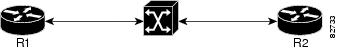
In Figure 1, assume PVCs are configured between router R1 and router R2 , and that OAM management is enabled on both ends of the PVC. Router R1, upon receiving OAM command cells from router R2, can stop its own OAM command cell transmission and can manage the link on the basis of incoming OAM command cells. Router R1 can reinitiate OAM command cell transmission upon discovering the absence of command cells from router R2.
Figure 1 ATM OAM Traffic Flow
When router R1 detects the first OAM command cell from router R2, time stamp T1 is noted. When the next OAM command cell is detected, time stamp T2 is noted. The interval T1 minus T2 provides the OAM the loopback frequency of router R2. The average value of this interval is taken by measuring it a random number of times. (The interval needs to be taken a random number of times to avoid a race condition that might happen when routers R1 and R2 implement this algorithm and the frequency is the same.)
At the end of the random time period, router R1 stops sending OAM command cells and starts the OAM traffic monitoring timer. This timer in router R1 checks for a change in interval frequency in router R2. If there is a change, the traffic monitoring timer is stopped and the VC goes into Retry mode and checks whether the link is still up. In Retry mode, OAM command loopback cells are transmitted at an interval of one per second for 3 seconds. If router R1 does not receive a response to the command cell, the link is changed to the Down state.
Note
If this feature is enabled on only one router (R1, for example), then the frequency of that router must be greater than or equal to the interval frequency set in the other router (R2) in order for router R1 to stop sending OAM command cells.
The ATM OAM Traffic Reduction feature is enabled by the oam-pvc command. When the optimum keyword is enabled, and when a change in the interval frequency of router R2 is detected, the VC initiates an OAM command cell from router R1 and does not go into the Retry mode immediately. If no response is obtained, the VC goes into the Retry mode and follows the OAM Retry procedure.
How to Configure ATM OAM Traffic Reduction
This section contains the following procedures.
•
•
•
Configure ATM OAM Traffic Reduction on an ATM Interface
To configure ATM OAM traffic reduction on an ATM interface, use the following commands.
SUMMARY STEPS
1.
2.
3.
4.
5.
6.
DETAILED STEPS
Configure ATM OAM Traffic Reduction on a VC Class
To configure ATM OAM traffic reduction on a VC class, use the following commands.
SUMMARY STEPS
1.
2.
3.
4.
5.
6.
7.
8.
DETAILED STEPS
Verify ATM OAM Traffic Reduction
To verify that the ATM OAM Traffic Reduction feature is working, perform the following steps.
SUMMARY STEPS
1.
2.
3.
DETAILED STEPS
Configuration Examples for ATM OAM Traffic Reduction
This section provides the following configuration examples to match the identified configuration tasks in the previous section:
•
•
•
ATM OAM Traffic Reduction on an ATM Interface: Example
The following example enables ATM OAM traffic reduction on an ATM interface:
interface atm 1/0pvc 0/100oam-pvc manage 10 auto-detect optimumATM OAM Traffic Reduction on a VC Class: Example
The following example enables ATM OAM traffic reduction using a VC class:
class-vc atmoam-pvc manage 10 auto-detect optimuminterface atm 1/0class-int testpvc 0/100pvc 0/200Verify ATM OAM Traffic Reduction: Example
In the following examples, the output is displayed for each command in the task.
Sample Output for the show atm oam auto-detect Command
The following is sample output from the show atm oam auto-detect command:
Router# show atm oam auto-detect atm 2/0ATM OAM Auto Detect statistics on ATM2/0Number of VCs in Auto Detection:ATM OAM AUTO DETECT INIT : 0ATM OAM SENDING MONITORING : 0ATM OAM MONITORING : 0Number of VCs in OAM Loopback:DownRetry : 0UpRetry : 0Verified : 0Not Verified : 0Sample Output for the show atm pvc Command
The following is sample output from the show atm pvc command with ATM OAM traffic reduction enabled:
Router# show atm pvc 0/100ATM1/0: VCD: 1, VPI: 0, VCI: 100UBR, PeakRate: 149760AAL5-LLC/SNAP, etype:0x0, Flags: 0xC20, VCmode: 0x0OAM frequency: 10 second(s), OAM retry frequency: 1 second(s)OAM up retry count: 3, OAM down retry count: 5OAM Loopback status: OAM ReceivedOAM VC state: VerifiedOAM Auto Detect state: ATM OAM AUTO DETECT INITOAM PEER frequency: 0 second(s)Last OAM Command Cell was received at 00:02:09ILMI VC state: Not ManagedAdditional References
The following sections provide references related to ATM OAM Traffic Reduction:
Related Documents
Configuring VC management
"Configuring ATM" chapter in the Cisco IOS Wide-Area Networking Configuration Guide, Release 12.4
VC management commands
"ATM Commands" chapter in the Cisco IOS Wide-Area Networking Command Reference, Release 12.4T
Standards
ITU-I Specification
I.610 SERIES I: INTEGRATED SERVICES DIGITAL NETWORK, Maintenance principles
MIBs
None
To locate and download MIBs for selected platforms, Cisco IOS releases, and feature sets, use Cisco MIB Locator found at the following URL:
RFCs
Technical Assistance
Command Reference
This section documents modified commands only.
oam-pvc
To enable end-to-end F5 Operation, Administration, and Maintenance (OAM) loopback cell generation and OAM management for an ATM permanent virtual circuit (PVC), virtual circuit (VC) class, or label-controlled ATM (LC-ATM) VC, use the oam-pvc command in the appropriate command mode. To disable generation of OAM loopback cells and OAM management, use the no form of this command.
ATM VC or VC Class
oam-pvc [manage] [frequency]
no oam-pvc [manage]
LC-ATM VC
oam-pvc manage [frequency]
no oam-pvc manage
Loopback Mode Detection
oam-pvc manage [frequency] loop-detection
no oam-pvc manage loop-detection
Syntax Description
Defaults
Disabled.
Command Modes
Interface-ATM-VC configuration (for an ATM PVC or Loopback Mode Detection)
VC-class configuration (for a VC class)
PVC-in-range configuration (for an individual PVC within a PVC range)
Control-VC configuration (for enabling OAM management on an LC-ATM VC)Command History
Usage Guidelines
If OAM management is enabled, further control of OAM management is configured using the oam retry command.
ATM VCS or VC Classes
If the oam-pvc command is not explicitly configured on an ATM PVC, the PVC inherits the following default configuration (listed in order of precedence):
•
•
•
•
Loopback Mode Detection
When a PVC traverses an ATM cloud and OAM is enabled, the router sends a loopback cell to the other end and waits for a response to determine whether the circuit is up. If an intervening router within the ATM cloud is in loopback mode, however, the router considers the circuit to be up, when in fact the other end is not reachable.
When enabled, the Loopback Mode Detection Through OAM feature detects when an intervening router is in loopback mode, in which case it sets the OAM state to NOT_VERIFIED. This prevents traffic from being routed on the PVC for as long as any intervening router is detected as being in loopback mode.
Examples
The following example shows how to enable end-to-end F5 OAM loopback cell transmission and OAM management on an ATM PVC with a transmission frequency of 3 seconds:
Router(cfg-mpls-atm-cvc)# oam-pvc manage 3The following example shows how to enable end-to-end F5 OAM loopback cell transmission and OAM management on an LC-ATM interface with a transmission frequency of 2 seconds:
Router(config)# interface Switch1.10 mplsRouter(config-subif)# ip unnumbered Loopback0Router(config-subif)# mpls atm control-vc 0 32Router(cfg-mpls-atm-cvc)# oam-pvc manage 2The following example shows how to create a PVC and enable loopback detection:
Router(config)# interface ATM1/0Router(config-if)# pvc 4/100Router(config-if-atm-vc)# oam-pvc manage loop-detectionRelated Commands
show atm oam auto-detect
To display ATM Operations and Maintenance (OAM) autodetect statistics, use the show atm oam auto-detect command in privileged EXEC mode.
show atm oam auto-detect [atm interface-number]
Syntax Description
atm interface-number
(Optional) Specifies a particular ATM interface rather than all ATM interfaces.
Command Default
No default behavior or values.
Command Modes
Privileged EXEC
Command History
12.0(23)S
This command was introduced.
12.2(28)SB
This command was integrated into Cisco IOS Release 12.2(28)SB.
Usage Guidelines
Use this command to check the state of the OAM cells when ATM OAM traffic reduction is enabled.
Examples
The following is sample output from the show atm oam auto-detect command:
Router# show atm oam auto-detect atm 2/0ATM OAM Auto Detect statistics on ATM2/0Number of VCs in Auto Detection:ATM OAM AUTO DETECT INIT : 0ATM OAM SENDING MONITORING : 0ATM OAM MONITORING : 0Number of VCs in OAM Loopback:DownRetry : 0UpRetry : 0Verified : 0Not Verified : 0Table 1 describes the significant fields shown in the display.
Related Commands
show atm pvc
To display all ATM permanent virtual connections (PVCs) and traffic information, use the show atm pvc command in privileged EXEC mode.
show atm pvc [vpi/vci | name | interface atm interface-number[.subinterface-number multipoint]] [ppp]
Syntax Description
Command Modes
Privileged EXEC
Command History
Usage Guidelines
If the vpi/vci or name argument is not specified, the output of this command is the same as that of the show atm vc command, but only the configured PVCs are displayed.
If the vpi/vci or name argument is specified, the output of this command is the same as that of the show atm vc vcd command, with extra information related to PVC management, including connection name, detailed states, and Operation, Administration, and Maintenance (OAM) counters.
If the interface atm interface-number option is included in the command, all PVCs under that interface or subinterface are displayed.
Examples
The following is sample output from the show atm pvc command. The output is the same as that of the show atm vc command, but only the configured PVCs are displayed:
Router# show atm pvcVCD/ Peak Avg/Min BurstInterface Name VPI VCI Type Encaps Kbps Kbps Cells Sts2/0 1 0 5 PVC SAAL 155000 155000 UP2/0 2 0 16 PVC ILMI 155000 155000 UP2/0.2 101 0 50 PVC SNAP 155000 155000 UP2/0.2 102 0 60 PVC SNAP 155000 155000 DOWN2/0.2 104 0 80 PVC SNAP 155000 155000 UP2/0 hello 0 99 PVC SNAP 1000 UPThe following is sample output from the show atm pvc command with the vpi/vci argument specified:
Router# show atm pvc 0/41ATM2/0: VCD: 3, VPI: 0, VCI: 41UBR, PeakRate: 155000AAL5-LLC/SNAP, etype:0x0, Flags: 0xC20, VCmode: 0x0OAM frequency: 0 second(s), OAM retry frequency: 1 second(s), OAM retry frequency: 1 second(s)OAM up retry count: 3, OAM down retry count: 5OAM Loopback status: OAM DisabledOAM VC state: Not ManagedOAM Loop detection: DisabledILMI VC state: Not ManagedInARP frequency: 15 minutes(s)InPkts: 31759, OutPkts: 26497, InBytes: 2356434, OutBytes: 1589743InPRoc: 15785, OutPRoc: 26472, Broadcasts: 0InFast: 20, OutFast: 20, InAS: 15954, OutAS: 6OAM cells received: 0F5 InEndloop: 0, F5 InSegloop: 0, F5 InAIS: 0, F5 InRDI: 0F4 InEndloop: 0, F4 InSegloop: 0, F4 InAIS: 0, F4 InRDI: 0OAM cells sent: 0F5 OutEndloop: 0, F5 OutSegloop: 0, F5 OutRDI: 0F4 OutEndloop: 0, F4 OutSegloop: 0, F4 OutRDI: 0OAM cell drops: 0Status: UPPPPOE enabled.The following sample output from the show atm pvc command displays OAM cell emulation statistics, which are marked in this example by exclamation points:
Router# show atm pvc 5/500ATM4/1/0.200: VCD: 6, VPI: 5, VCI: 500UBR, PeakRate: 1AAL5-LLC/SNAP, etype:0x0, Flags: 0x34000C20, VCmode: 0x0OAM Cell Emulation: enabled, F5 End2end AIS Xmit frequency: 1 second(s) !!!OAM frequency: 0 second(s), OAM retry frequency: 1 second(s)OAM up retry count: 3, OAM down retry count: 5OAM Loopback status: OAM DisabledOAM VC state: Not ManagedVerifiedOAM Loop detection: DisabledILMI VC state: Not ManagedInPkts: 564, OutPkts: 560, InBytes: 19792, OutBytes: 19680InPRoc: 0, OutPRoc: 0InFast: 4, OutFast: 0, InAS: 560, OutAS: 560InPktDrops: 0, OutPktDrops: 0CrcErrors: 0, SarTimeOuts: 0, OverSizedSDUs: 0Out CLP=1 Pkts: 0OAM cells received: 26F5 InEndloop: 0, F5 InSegloop: 0, F5 InAIS: 0, F5 InRDI: 26OAM cells sent: 77F5 OutEndloop: 0, F5 OutSegloop: 0, F5 OutAIS: 77, F5 OutRDI: 0 !!!OAM cell drops: 0Status: UPThe following is sample output from the show atm pvc command with the ATM subinterface specified:
Router# show atm pvc interface atm 2/0.2VCD/ Peak Avg/Min BurstInterface Name VPI VCI Type Encaps Kbps Kbps Cells Sts2/0.2 101 0 50 PVC SNAP 155000 155000 UP2/0.2 102 0 60 PVC SNAP 155000 155000 DOWN2/0.2 104 0 80 PVC SNAP 155000 155000 UPThe following is sample output from the show atm pvc command for a PVC that is a member of a multilink PPP bundle:
Router# show atm pvc 15/200ATM4/0.10000:VCD:16, VPI:15, VCI:200UBR, PeakRate:149760 (353208 cps)AAL5-LLC/SNAP, etype:0x0, Flags:0xC20, VCmode:0x0, Encapsize:12OAM frequency:0 second(s), OAM retry frequency:1 second(s)OAM up retry count:3, OAM down retry count:5OAM Loopback status:OAM DisabledOAM VC State:Not ManagedOAM Loop detection: DisabledILMI VC status:Not ManagedVC TxRingLimit:40 particlesVC Rx Limit:800 particlesInARP frequency:15 minutes(s)Transmit priority 6InPkts:347, OutPkts:399, InBytes:6268, OutBytes:7728InCells:347, OutCells:399InPRoc:7, OutPRoc:228InFast:338, OutFast:169, InAS:0, OutAS:0InPktDrops:0, OutPktDrops:0/0/0 (holdq/outputq/total)InCellDrops:0, OutCellDrops:0InByteDrops:0, OutByteDrops:0CrcErrors:0, SarTimeOuts:0, OverSizedSDUs:0, LengthViolation:0, CPIErrors:0Out CLP=1 Pkts:0, Cells:0OAM cells received:0F5 InEndloop:0, F5 InSegloop:0, F5 InAIS:0, F5 InRDI:0F4 InEndloop:0, F4 InSegloop:0, F4 InAIS:0, F4 InRDI:0OAM cells sent:0F5 OutEndloop:0, F5 OutSegloop:0, F5 OutRDI:0F4 OutEndloop:0, F4 OutSegloop:0, F4 OutRDI:0OAM cell drops:0Status:UPPPP:Virtual-Access3 from Virtual-Template1PPPoA Current State = LOCALLY_TERMINATEDPPPoA Latest Event = Vaccess UpPPPoA Latest Error = NonePPPoA Session ID = 7PPPoA Handle = 0x4D000006, SSS Handle = 0x00000000Switch Handle = 0xB5000006, PPP Handle = 0xD700000AAAA Unique ID = 0x00000007, AIE Handle = 0xE7000006PVC belongs to Multilink PPP Bundle Virtual-Access4 as a PPPoA member linkPackets in VC Holdq:0 , Particles in VC Tx Ring:0The following is sample output from the show atm pvc command with loopback detection mode through OAM enabled:
Router# show atm pvc 4/100ATM1/0: VCD: 4, VPI: 4, VCI: 100UBR, PeakRate: 149760AAL5-LLC/SNAP, etype:0x0, Flags: 0xC20, VCmode: 0x0!OAM frequency: 10 second(s), OAM retry frequency: 1 second(s)OAM up retry count: 3, OAM down retry count: 5OAM Loopback status: OAM ReceivedOAM VC state: VerifiedOAM Loop detection: Enabled ! Indicates that loopback mode detection is enabled.!ILMI VC state: Not ManagedVC is managed by OAM.InARP frequency: 15 minutes(s)Transmit priority 4InPkts: 0, OutPkts: 0, InBytes: 0, OutBytes: 0InPRoc: 0, OutPRoc: 0, Broadcasts: 0InFast: 0, OutFast: 0, InAS: 0, OutAS: 0InPktDrops: 0, OutPktDrops: 0CrcErrors: 0, SarTimeOuts: 0, OverSizedSDUs: 0Out CLP=1 Pkts: 0OAM cells received: 27F5 InEndloop: 27, F5 InSegloop: 0, F5 InAIS: 0, F5 InRDI: 0OAM cells sent: 27F5 OutEndloop: 27, F5 OutSegloop: 0, F5 OutAIS: 0, F5 OutRDI: 0OAM cell drops: 3Status: UPThe following is sample output from the show atm pvc command when loopback mode has been detected:
Router# show atm pvc 4/100ATM1/0: VCD: 4, VPI: 4, VCI: 100UBR, PeakRate: 149760AAL5-LLC/SNAP, etype:0x0, Flags: 0xC20, VCmode: 0x0!OAM frequency: 10 second(s), OAM retry frequency: 1 second(s)OAM up retry count: 3, OAM down retry count: 5OAM Loopback status: OAM SentOAM VC state: Not VerifiedOAM Loop detection: Enabled, Detected ! Indicates that loopback mode has been detected on this interface.!ILMI VC state: Not ManagedVC is managed by OAM.InARP frequency: 15 minutes(s)Transmit priority 4InPkts: 0, OutPkts: 0, InBytes: 0, OutBytes: 0InPRoc: 0, OutPRoc: 0, Broadcasts: 0InFast: 0, OutFast: 0, InAS: 0, OutAS: 0InPktDrops: 0, OutPktDrops: 0CrcErrors: 0, SarTimeOuts: 0, OverSizedSDUs: 0Out CLP=1 Pkts: 0OAM cells received: 20F5 InEndloop: 20, F5 InSegloop: 0, F5 InAIS: 0, F5 InRDI: 0OAM cells sent: 20F5 OutEndloop: 20, F5 OutSegloop: 0, F5 OutAIS: 0, F5 OutRDI: 0OAM cell drops: 1Status: DOWN, State: NOT_VERIFIEDTable 2 describes the significant fields shown in the display.
Table 2 show atm pvc Field Descriptions
Interface
Interface and subinterface slot and port.
VCD/Name
Virtual connection descriptor (virtual connection number). The connection name is displayed if a name for the VC was configured using the pvc command.
VPI
Virtual path identifier.
VCI
Virtual channel identifier.
Type
Type of PVC detected from PVC discovery, either PVC-D, PVC-L, or PVC-M:
•
•
•
Encaps
Type of ATM adaptation layer (AAL) and encapsulation.
Peak
or
PeakRate
Kilobits per second sent at the peak rate.
Avg/Min
or
Average Rate
Kilobits per second sent at the average rate.
Burst Cells
Maximum number of ATM cells that the VC can send at peak rate.
Sts or Status
Status of the VC connection:
•
•
•
Connection Name
Name of the PVC.
UBR, UBR+, or VBR-NRT
•
•
•
etype
Encapsulation type.
Flags
Bit mask describing VC information. The flag values are summed to result in the displayed value:
•
•
•
•
•
•
•
•
•
•
•
•
virtual-access
Virtual-access interface identifier.
virtual-template
Virtual template identifier.
VCmode
AIP-specific or NPM-specific register describing the usage of the VC. This register contains values such as rate queue, peak rate, and AAL mode, which are also displayed in other fields.
OAM Cell emulation
The status of the OAM cell emulation functionality. It is either enabled or disabled.
F5 end2end AIS xmit frequency
Number of seconds between transmission of AIS cells.
OAM frequency
Number of seconds between transmission of OAM loopback cells.
OAM retry frequency
Frequency (in seconds) at which end-to-end F5 loopback cells should be sent when a change in state (up or down) is being verified. For example, if a PVC is up and a loopback cell response is not received after the value of the frequency argument (in seconds) specified using the oam-pvc command, loopback cells are sent at the value of the retry-frequency argument to determine whether the PVC is down.
OAM up retry count
Number of consecutive end-to-end F5 OAM loopback cell responses that must be received in order to change a PVC state to up. Does not apply to SVCs.
OAM down retry count
Number of consecutive end-to-end F5 OAM loopback cell responses that are not received in order to change a PVC state to down or tear down an SVC.
OAM Loopback status
Status of end-to-end F5 OAM loopback cell generation for this VC. This field will have one of the following values:
•
•
•
•
OAM VC state
This field will have one of the following states for this VC:
•
•
•
•
•
•
OAM Loop detection
Status of loopback detection mode through OAM:
•
•
•
ILMI VC state
This field will have one of the following states for this VC:
•
•
•
VC is managed by OAM/ILMI
VC is managed by OAM or ILMI.
InARP frequency
Number of minutes for the Inverse Address Resolution Protocol (ARP) time period.
InPkts
Total number of packets received on this VC. This number includes all fast-switched and process-switched packets.
OutPkts
Total number of packets sent on this VC. This number includes all fast-switched and process-switched packets.
InBytes
Total number of bytes received on this VC. This number includes all fast-switched and process-switched bytes.
OutBytes
Total number of bytes sent on this VC. This number includes all fast-switched and process-switched bytes.
InPRoc
Number of process-switched input packets.
OutPRoc
Number of process-switched output packets.
Broadcasts
Number of process-switched broadcast packets.
InFast
Number of fast-switched input packets.
OutFast
Number of fast-switched output packets.
InAS
Number of autonomous-switched or silicon-switched input packets.
OutAS
Number of autonomous-switched or silicon-switched output packets.
OAM cells received
Total number of OAM cells received on this VC.
F5 InEndloop
Number of end-to-end F5 OAM loopback cells received.
F5 InSegloop
Number of segment F5 OAM loopback cells received.
F5 InAIS
Number of F5 OAM AIS cells received.
F5 InRDI
Number of F5 OAM RDI cells received.
F4 InEndloop
Number of end-to-end F4 OAM loopback cells received.
F4 InSegloop
Number of segment F4 OAM loopback cells received.
F4 InAIS
Number of F4 OAM AIS cells received.
F4 InRDI
Number of F4 OAM RDI cells received.
OAM cells sent
Total number of OAM cells sent on this VC.
F5 OutEndloop
Number of end-to-end F5 OAM loopback cells sent.
F5 OutSegloop
Number of segment F5 OAM loopback cells sent.
F5 OutRDI
Number of F5 OAM RDI cells sent.
OAM cell drops
Number of OAM cells dropped (or flushed).
PVC Discovery
•
•
•
•
•
•
•
Status
When the Status field indicates UP, the VC is established. When the Status field indicates DOWN, refer to the State field for further information about the VC state.
State
When the Status field is UP, this field does not appear. When the Status field is DOWN or INACTIVE, the State field will appear with one of the following values:
•
•
•
•
•
•
•
•
PPP
For PPP over ATM, indicates the virtual access interface number and virtual template number being used.
PPPoA Current State
State of the PPPoA session associated with the VC.
PPPoA Latest Event
The latest event that occurred on the PPPoA session associated with the VC.
PPPoA Latest Error
The latest error that occurred on the PPPoA session associated with the VC.
PPPoA Session ID
PPPoA session identifier of the PPPoA session associated with the VC.
PPPoA Handle
PPPoA context handle.
SSS Handle
SSS handle for PPPoA session associated with the VC.
Switch Handle
SSS handle for switch management.
PPP Handle
Handle associated with the PPP context.
AAA Unique ID
Unique identifier associated with the AAA session.
AIE Handle
Access IE handle for the PPPoA session.
Packets in VC Holdq
Number of packets in the hold queue of the VC.
Particles in VC Tx Ring
Number of particles in the Tx ring of the VC.
1 QoS = quality of service
2 AIS = alarm indication signal
3 RDI = remote defect identification
4 ILMI = Interim Local Management Interface
Any Internet Protocol (IP) addresses used in this document are not intended to be actual addresses. Any examples, command display output, and figures included in the document are shown for illustrative purposes only. Any use of actual IP addresses in illustrative content is unintentional and coincidental.
© 2002, 2006 Cisco Systems, Inc. All rights reserved.